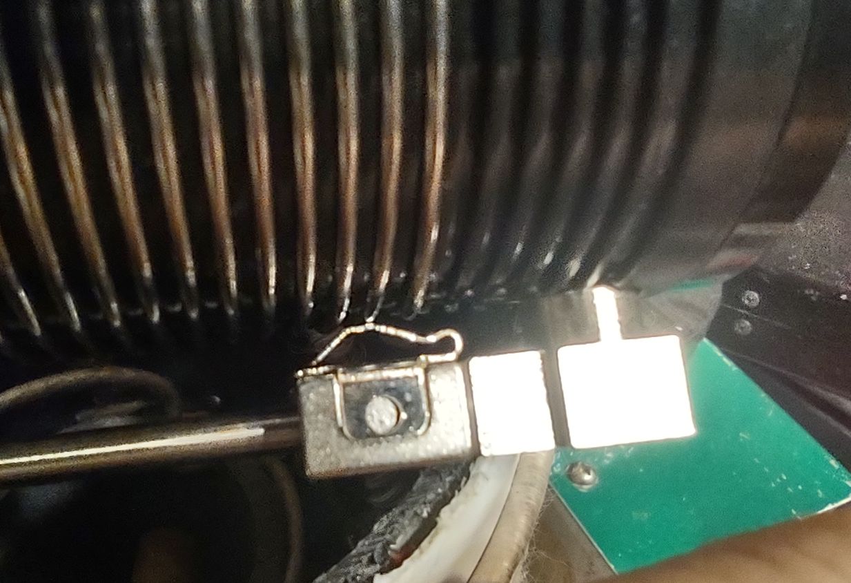
The
coils have painted markings indicating "approximate" locations of the tap
for both 20 and 40 meters when the telescoping section is adjusted as
described in the manual. These coils are wound with 1mm diameter (approx. 18 AWG) 316 stainless steel wire: The
maximum inductance is a bit over 20uH and the DC resistance of the full coil is about 4
ohms - more on this later.
- 5/8" male stud mount.
This antenna comes with a machined aluminum mount (seen in Figure 4) that screws into 1/2" NPT threads in the
center support that is a 5/8" stud mount - sometimes referred to as a
"Gaffer" or "Grip" mount - of the sort found everywhere on tripods used
for holding photographic lights.
- 10mm x 1.5mm thread.
If you want to configure this antenna as a dipole, you also have the option
of using a 10mm x 1.5mm thread that is on the side opposite the female
threads into which the 5/8" stud mount screws - but this should not be your first choice as it will put a fair bit of stress into a small mechanical connection. While this thread isn't
particularly common in the U.S.A., it would seem that this is a common size for portable antennas everywhere else in the world and hardware of this size is available at larger U.S. hardware stores. As this mounting point may be used as part of the antenna
 |
Figure 5:
A homebrew double-female 5/8 stud adapter. These adapters
have 3/8" threads and were attached using a thread
coupler. This piece was necessary as both the antenna and my
tripod have male 5/8" stud mounts on them!
Click on the image for a larger version.
|
(when configured in an "L" shape or if configured as a vertical-only) so it's the same threads as the screw-in element sections.
For
me the 5/8" male stud mount is the most useful as it happens that I have
on hand an old gaffer tripod (light stand) of this sort - but there's a catch: It,
too, has a 5/8" male stud mount! It would seem that these tripods come both ways - with
either a male or female 5/8" mount, but for less than US$15 I was able to
construct a "double-female" adapter that solved the problem. From Amazon, I ordered two 5/8 female stud to 3/8"-16 adapters and coupled them together with a 3/8" thread coupler as seen in Figure 5. The only "trick" with this was that I had to sort through my collection of flat washers to find the combination of thicknesses that resulted in both knobs facing the same direction when the adapters were tightened to the thread coupler - and the reason for this is so that it would store flat in the case with both knobs oriented as shown above.
Element configuration
As with any antenna that you are likely to come across, the only portions of the antenna that actually radiate energy in the far field are those with current flowing through them: The higher the current, the more energy is radiated. By extension, the very ends of the wire - or, in this case, the ends of the telescoping section - have essentially zero current and do not radiate. As the total length of conductors prior to the loading coil (screw-together sections, feedpoint mount, connecting wires) is about 56" (1.42 meters) this represents only about 3.6% of a wavelength at 40 meters.
It is for this reason that the preferred configuration is to have the screw-together sections connected directly to the feedpoint mount, then the loading coil and then the telescoping section, placing the loading coils nearly 30" (75cm) from the feed. As the total length of the telescoping sections alone put together is about 198" (5 meters) - which is about 12.5% of a wavelength at 40 meters - you might think that they are doing the lions share of radiating - but that's not really the case.
Particularly at lower bands, it is understandable why coil losses are of such importance - and also why even a relatively small amount of lengthening of the antenna can improve performance on the lower frequencies: Adding two more screw-together sections (one per side) increase the length "before the loading coil" from 56" to 84" (2.13 meters) - or about 5.3% of a wavelength and not only increase the aperture of the antenna, but it will also allow a reduction of the amount of inductance (and coil loss) required to resonate the antenna.
Further improvement can be made by adding a bit of extra length to the telescoping whips by clipping hanging wires to the end of it: This will further reduce the amount of inductance needed to resonate, but it will also increase the effective portion of the whips that are carrying RF current. (This is discussed further in the section on 60 meter coverage, below.)
Frequency coverage
(This section presumes that the original, stainless-steel wound coils are being used.)
This antenna is advertised to cover 40 through 6 meters - and this is certainly true: When the four supplied mast sections are installed (two per side) the lowest frequency at which it can be resonated with the telescoping rods at full extension and the inductors set at maximum is around 6.7-6.8 MHz - well below the entirety of the 40 meter band.
On 40 meters, the 2:1 VSWR bandwidth was typically around 120 kHz: A 2:1 VSWR is about the maximum mismatch at which most modern radios will operate at full power before SWR "foldback" occurs, reducing transmit power. Of course, if your radio has a built-in tuner - even one with a limited range - you will certainly be able to make the radio "happy" across the entire 40 meter band without fussing with the antenna, even if it isn't tuned exactly to your operating frequency.
On the other extreme, with the minimum coil inductance and the two telescoping rods at maximum extension the resonant frequency was about 21.7 MHz: This means that for all amateur bands 15 meters and lower, you will need the inductors - but for 12 meters and up you can omit them entirely (which is recommended!), bringing the antenna to resonance solely by adjusting the length of the telescoping sections.
Tuning the antenna
This may be where some people have issues. I am very comfortable using a NanoVNA: I have several of these as they are both cheap and extremely useful - the only down-side really being that their screens are not easily viewed in direct sunlight - but simply standing with my back to the sun was enough to make it usable as all one is trying to see is the trace on the screen rather than any fine detail.
The biggest advantage of the NanoVNA over a traditional antenna analyzer is that you get the "big picture" of what is going on: You can instantly see where the antenna is resonant - and how good the match may be. More importantly, you can see at a glance if the antenna is tuned high (too little inductance) or too low (too much inductance) and make adjustments accordingly whereas using a conventional antenna analyzer will require you to sweep up and down: Still do-able, but less convenient.
Tuning is somewhat complicated by two factors:
- There are two coils to adjust - and they must both be pretty close to each other in terms of adjustment to get the best match. Simply looking at the coils one can "eyeball" the settings of the slider/contact to get them very close to each other - something that becomes easier with practice.
- The "resolution" of the inductors' adjustments is limited by the fact that one can make adjustments by one turn at a time with the slider. At 20 meters and higher, being able to only adjust inductance one turn at a time is likely to result in the best match being just above or below the desired frequency. At lower frequencies (lots of turns) - say 40 and 30 meters - you can likely get 2:1 or better by adjusting the coil taps alone, but at higher frequencies you will likely need to tune for the best match just below the frequency of interest and then shorten the telescoping rods slightly to bring it right onto frequency.
Once I'd used the antenna a few times I found that I could change bands in 2-3 minutes as I would:
- Lower the antenna to shoulder height so that the coils and telescoping rods may be reached. If you had previously shortened the telescoping elements for fine-tuning a band you should reset them to full length.
- Set the NanoVNA to cover from the frequency to which it is already tuned and where I want to go: If I was setting it up for the first time I would set the 'VNA to cover above and below the desired frequency by 5 MHz or so so I could see the resonant point even when it was far off-frequency. After using it a few times you will remember about where the coil taps need to be set for a particular band.
- On the NanoVNA I would then set a marker to the desired operating frequency.
- I would then "walk" both coils up/down to the desired frequency while watching the 'VNA. As the tuning of the elements interact, you may have to iterate a bit to get the VSWR down. Again, you may have to tune for best match at a frequency just below the target frequency and then shorten the telescoping sections.
- I would raise the mast to full height again. I noticed a slight increase in resonant frequency (particularly on the lower bands - 40 and 30 meters) by raising the antenna on the order of 50 kHz on 40 meters. Usually, this doesn't matter, but with a bit of practice/experience you'll be able to compensate for this while tuning.
- A match of 2:1 or better was easily obtained - but don't expect to get a 1:1 match all of the time as the only adjustments are those of resonating the elements and nothing to take into account the actual feedpoint resistance at resonance. Practically speaking, there is no performance difference between a 2:1 and 1:1 match unless your radio's power drops back significantly: An antenna tuner could be used, but this will surely insert more loss than having a modest mismatch!
 |
Figure 6:
As with almost any inductor adjustable using sliders, care
should be taken to assure that only one turn is being touched
by the contact, as shown.
Click on the image for a larger version.
|
All of that sounds complicated - and it may be, the first time doing it - but I found it to be very quick and easy, particularly after even just a
little bit of practice!
The "card" trick
Another "trick" that I have done is to use a piece of thick paper (card stock) and mark along its edge the top and bottom of the coil and then - as you find tuning for each band - mark the position of the slider: Using this as a "template" will quickly get you to within one turn of the coil(s) for each band.
Be sure to mark on the card how the antenna is configured (e.g. where the coil is located, number of pipe sections, if you used wires at the ends of the antenna) so that the configuration can be replicated in the future. If this card is laminated and kept with the antenna in its carry bag, it will withstand repeated use.
Carefully adjusting coil taps
If you look very carefully at the sliding coil taps you'll notice that if very carefully adjusted that they will contact just one turn of wire - but it is almost easier for the contact spring to bridge two turns of wire, shorting them together. When this happens the inductance will go down slightly and you may see the resonance go up in frequency unexpectedly. Additionally, the shorting of two turns can also reduce the "Q" (and efficiency) of the coil slightly.
If you are aware of this situation - which can occur with nearly
all tapped inductors adjusted with a slider - you can start to "feel" when the slider bridges two turns of the coil and avoid its happening as you make the adjustments.
* * *
Suggested modifications/additions:
All electrically-short antennas that require series inductance for tuning to resonance - like this one - will lose efficiency due to losses in the coil, but this can be offset - at least somewhat - by increasing the length of the elements themselves. One of the easiest ways to do this is to purchase a couple of extra screw-on mast sections: The addition of one on each side will increase the total length of the antenna by about 25" (64cm) and allow a slight decrease in the required inductance - resulting in slightly lower loss and increase the aperture of the antenna slightly. These additional screw-on sections are typically available from the sellers of the antenna for between US $10 and $15 each but are often called something like "Dedicated lengthened vibrator for JPC-7 (JPC-12)" or similar due to quirks of the translation.
60 meter operation
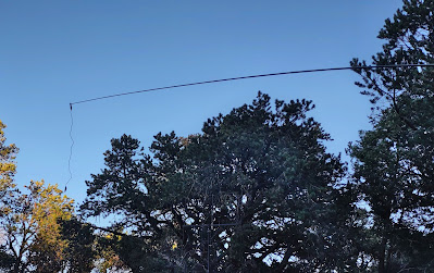 |
Figure 7:
The elements may be lengthened by clipping a lead to each
end of the telescoping sections, reducing the amount of
needed inductance - and also allowing resonance on lower
bands - in this case, 60 meters.
Click on the image for a larger version.
|
While adding two additional sections (on on each side, between the coil and the whip) - and rearranging the antenna with the coils located next to the feedpoint (rather than the usual configuration in which the coils are located away from the feedpoint) - will bring the resonant frequency down to about 5.7 MHz with full inductance and extension of the telescoping sections. In this configuration, the added length beyond the coil adds significant capacitance, lowering the resonant frequency as compared to the normal coil location
The antenna can be made to cover 60 meters by clipping on short (18" or 46cm) jumper leads to the very end of the antenna elements and let them hang down. Despite this being a less desirable configuration in terms of RF current distribution, in testing on the air, the signals were about 1 or 2 "S" units below a full-sized dipole, but still quite good for a fairly compact antenna that was close to the ground in terms of wavelength.
If you wish to use the "stock" antenna on 60 meters rather than buying two extra screw-together sections, you'll need about 48" (1.25 meters) of wire on each end: For this I simply used two pair of 24" (approx. 100cm) clip leads connected end-to-end, each pair hanging from the tips of the telescoping section.
Longer is better
Of course these "extension" leads can be used for all bands for which the coils are needed to lower the inductance and reduce losses: As it will always be the parts of the antenna that carry the most RF current that radiates the vast majority of the signal - and since those portions will always be the sections right near the coils for this type of antenna - adding these dropping wires at the ends won't appreciably affect the antenna pattern or its polarization.
As there is plenty of room to do so in the zipper case, I have since added two extra sections and two sets of "clip leads" permanently into the kit.
Get extra telescoping sections!
Finally, I would order at least two extra telescoping sections as these are the most fragile parts of the antenna kit. These can also be ordered from the same folks that sell the antennas for US $12-$16 each and are typically referred as something like "304 stainless steel 2.5M whip antenna for PAC-12 JPC7 portable shortwave antenna".
The reason for ordering two of them is that if the antenna falls over, both whips are likely to be damaged (ask me how I know!) The cost of getting two extra whips is likely to be less than the cost of fuel for even a modest road trip to wherever you are going, so their price should be kept in perspective. As the zippered case for the antenna has plenty of extra elastic loops inside, there is ready storage for these two extra whips with no modification.
A word of caution: However you store them, do not allow the telescoping whips to lay loosely in the case: If they bash into something else they can be easily dented which may make it impossible for them to be extended/retracted. For this reason they should be secured in the elastic strap, or individually in a tubes or padded cases.
Note: There are also available much heavier and longer telescoping whips with
the same M10x1.5 thread that would easily allow 60 meter coverage: I have not
tried these to see how well they would work, mechanically, or if it
would even be a good idea to do so (e.g. extra stress on the tubes, coils, mounting point - or how stable such a thing might be on a tripod).
 |
Figure 8:
The mounting of the balun, just below the feedpoint mount.
The index holes allow flexibility in the orientation, the
connection being made by 2.5mm banana plugs.
Here, the antenna is shown with the elements configured
one hole higher than "flat", forming a lazy "Vee"
shape as seen in Figures 9 and 10.
Click on the image for a larger version.
|
Additional comments:
"To vee, or not to vee"
The feedpoint mount has a number of indexed holes that allow the elements to be mounted in a variety of configurations, from flat, in a number of "Vee" configurations, or even an "L" or vertical configuration.
Personally, I use the flattest "Vee" configuration as seen in Figures 8, 9 and 10. This configuration keeps the drooping ends of the telescoping whips higher than the feedpoint and helps clear any local obstacles (trees!) - and just looks cool!
As can be seen in Figure 8, the connection between the balun and the feedpoint is made by plugging 2.5mm miniature banana plugs into the brass receptacles on the feed. Shown in the photo are connections to the two sides, typically used for a dipole arrangement, but the third, unused connection on the top could be used to hold an element horizontal while one of the side connections hold it vertical - more on the use of this antenna as a vertical in the next section.
It should be no surprise that these 2.5mm miniature banana plugs are quite small and fragile and if one isn't careful - say, by allowing the weight of the balun to be supported by the wires rather than using the hook-and-loop strap - they can be broken. For this reason I ordered a pack of ten 2.5mm banana plugs from Amazon and made a pair of short (4", 10cm) leads - one end with a small alligator clip and the other with a 2.5mm banana plug - to allow me to make a temporary connection should one get broken off in the field - something that can torpedo an activation if you didn't have spare parts!
Operating as a vertical antenna
Because of the flexibility of the mounting point, it is possible to use this same kit as a vertical antenna with the second element as a resonant (rod) ground "plane" if - due to space or personal preference - emitting a signal with a vertically-polarized component is desired. While this will certainly "work", if you do plan to operate with vertical polarization its recommended that you add several (2 or more) wire "radials" or counterpoises.
Because of the included balun (more on this in a moment) the coaxial feedline itself will not act as an effective part of the counterpoise network so rather than connecting additional radials to the shield, the ends of the wire should be clamped under the washer/bolt that holds the horizontally-configured element in place. Of course, one need not use the balun and connect the coaxial cable directly, but if you choose this option you will be on your own to supply the means to make such a connection.
For best results with the fewest number of radials, choosing lengths that are odd-number quarter wavelengths long (1/4, 3/4, 5/4) and keeping them elevated a foot (25cm) or more off the ground is suggested as this will help minimize "ground" losses. Having said this, almost no matter what you do, you will probably be able to radiate a useful amount of signal: Operating CW or digital modes offers an improvement in "talk" capability owing to their efficiency - but if you are planning to operate SSB, it's worth taking a bit of extra time and effort to maximize performance. Remember that just two elevated radials oriented in a straight line will produce a (mostly) omnidirectional pattern with nearly the performance as four radials while a single radial. Meanwhile, if you do use a single resonant radial (e.g. "counterpoise") the pattern will be somewhat lopsided, the peak in the direction of the wire.
Would I operate this antenna in "vertical" mode? While I don't have plans to do so, I have purchased an extra ground stake of the sort used on the JPC-12 vertical, and the short banana plug/clip lead jumpers that I made could be used to make a temporary connection directly to a coaxial connector.
Nature of the balun
For more details about the supplied balun, see the "Addendum" section at the end of this article.
The supplied balun has a 1:1 impedance ratio and has DC connection between the input and output - but since there is a DC connection between all of the conductors, it is more than a simple current balun (e.g. transmission line wound on ferrite). As the balun seems to work well, I have no reason to break it open to figure out what's inside, but I did a bit of "buzzing" of the connections with a meter to measure inductance and here are the results:
- Between coax shield and center conductor: 16.9uH
- Between red and black (on antenna side): 16.9uH
- Between center coax and black: 38.5uH
- Between center and red: 3.4uH
- Between Shield and black: 3.4uH
- Between Shield and red: 3.4uH
- The DC resistance between any combination of the leads is well under 1 ohm.
What does this tell us? The inductance readings of about 16.9uH indicate that this may be a voltage balun providing about 500 ohms of inductive reactance at 5 MHz - more than enough for reasonable efficiency. The interesting reading is the inductance between the center coaxial connection and the black wire which is only twice the inductance of the input or output windings: If there was a direct connection between one of the coax and one of the output wires this would imply twice the number of turns and four times the inductance - but since it is only twice, this indicates that the total number of turns in the "center coax to black" route is about sqrt(2) (or 1.414x) as many turns as the primary/secondary - or there is another inductor in there.
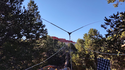 |
Figure 9:
The JPC-7 backgrounded by red rock during a POTA
operating in K-0010.
Click on the image for a larger version.
|
While I'm sure that the balun is very simple, its exact configuration/wiring escapes me at this time.
Addendum: I was able to figure out the configuration of the balun - see the note at the very end of this article.
Coil losses
As mentioned earlier, the coil is wound with 18 AWG (1mm diameter) type 316 stainless steel wire. Fortunately, this wire appears is austenitic - which is to say that it is not of the variety that is magnetic and thus has a permeability of unity: Were it magnetic, this would negatively impact performance significantly.
Knowing the diameter of the coil form and the fact that there are 34 turns, we know that the total length of the wire used is approximately 180 inches (457cm) and measurement shows that the stainless steel wire coil has a total DC resistance of about 4 ohms. Using Owen Duffy's online skin effect calculator (link to archived page)
and assuming 1mm diameter, 316 Stainless we can calculate the approximate RF resistance including skin effect - the tendency for RF to flow on the outside skin of a conductor rather than through its cross-section - versus frequency:
- 3.5 MHz = 5.2 ohms
- 7 MHz = 7.2 ohms
- 14 MHz = 9.6 ohms
- 28 MHz = 13.6 ohms
If I make a very broad assumption that the feedpoint resistance at each coil is about 25 ohms (the two in series being around 50 ohms) we can see that in this hypothetical situation about a third of the total resistance could be due to the coil, and since P = I2R - and if we presume that the current is consistent throughout the coil (it probably is not) we can roughly estimate that the total power loss will be proportional to the resistance implying that about 1/3rd of the total power is lost in the coil. In practical terms, a 33% power loss is around 4.8dB - still less than one "S" unit, so this loss may go unnoticed under typical conditions.
In operation, we would be unlikely to need all - or even most of the turns of the coil for operating on the higher bands, so the overall coil losses are likely to go down as the need for loading inductance at these frequencies is also significantly reduced: Since we actually use only about 2/3 of the turns of the coil on 40 meters, the loss is more likely to be something on the order of 5 ohms rather than 7.2, reducing the loss even more.
Note: K6STI's "coil" program - Link
- calculates the loss for this coil as being closer to 8 than 5 ohms - a
bit higher than the simple loss calculation of Owen Duffy's wire
calculation and likely more representative of in-situ measurements.
When operating on 40 meters with 100 watts of CW or SSB, the coils definitely do get quite warm - but not dangerously so and thus I would presume that the very rough estimates above are likely in the ballpark: If you operate heavy duty-cycle modes like RTTY or FT-8 and insist on running 100 watts key-down I would occasionally check the coils to be sure that they aren't getting too hot.
By comparison, the calculated DC resistance of the same length of 18 AWG bare copper wire is under 0.5 ohms, but the RF resistance due to skin effect at 28 MHz is around 2 ohms and about an ohm at 7 MHz - roughly a 7:1 difference meaning that if the above analysis is in any way close to being correct, our losses at 7 MHz when using the full coil (again, we don't!) and presuming that the feedpoint of the individual coil stayed at 25 ohms (it probably won't) our losses would drop from about 30% to less than 5%.
As a consequence, if wound with copper/silver plated I would expect that the not only would the antenna become narrower than the 40 meter 2:1 bandwidth of about 120 kHz - which would make it slightly trickier to tune - I would also expect the feedpoint resistance to drop, possibly increasing the VSWR at the feedpoint. From a practical standpoint, even a modest antenna tuner capable of handling only 3:1 mismatch should be able to cope with this, but it is likely that some of the gains from using lower-loss wire might be offset by the increase in losses caused by feedline mismatch and the losses within a tuner - both of which could easily exceed 3dB in a portable set-up with moderately-long, small-diameter coax.
Note: I have since rewound a coil with 18 AWG silver-plated copper jewelry wire and have done direct comparisons with it and the original coil wound with stainless-steel wire - you may read about those results in the blog entry Rewinding the Stainless Steel Coils with silver-plated copper wire on the JPC-7 and JPC-12 antennas.
Final comments
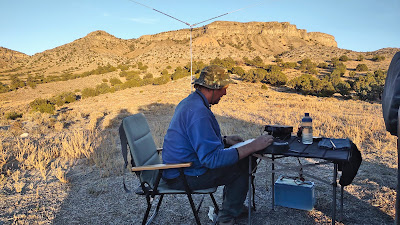 |
Figure 10:
Operating 20 meter CW from POTA entity K-6085, with the
Conger mountains and the JPC-7 dipole in the background.
Click on the image for a larger version.
|
Is this an antenna that is worth getting? I would have to say "yes".
Remembering that you will also need to supply a suitable tripod mount (e.g. an inexpensive "light stand" ) this antenna is quite portable and, if you have a bit of practice, quick to set up and adjust. Unlike a vertical antenna, it doesn't need a set of ground radials and it is likely that the antenna itself will be up and above everyone's heads when it is deployed.
Best used on the higher bands (20 and higher) its efficiency will be quite good - certainly equal to or better than a typical mobile antenna. As this is a large-ish antenna on a tripod, be sure to weigh down the legs and/or attach simple guying to it to prevent it from blowing over in the wind or being knocked over by tripping over the coax: I can attest personally that the latter can easily happen!
* * *
I also have the JPC-12 vertical (discussed in the link below) and I find this antenna (the JPC-7 loaded dipole, that is) to be far more convenient to use than the vertical (e.g. no radial system), particularly if you plan to change bands several times during the operation - something that is quite likely to happen on the higher bands as propagation varies over the course of a few hours. For the vertical, best performance requires adjusting the radials as well as the antenna itself, although it would probably work "just fine" if the radials are left at maximum length. Another advantage of the JPC-7 loaded dipole being a (largely) horizontally-polarized antenna is that in an urban environment it is likely to intercept less noise on receive than a vertical - and it can be inconspicuous in its deployment as compared to a taller vertical.
For the lower bands (40 and 30 meters) the JPC-7 works quite well - particularly if one operates CW or digital modes. As mentioned, it can also work competently on 60 meters as well with the addition of extra length of the elements by the purchasing of extra rods and/or simply attaching "drooping" wires to the ends of the telescoping rods.
Over the course of several POTA and related activations I have made about 500 contacts with this antenna on the bands 60 through 15 meters - on CW and voice: I'm sure that the antenna works well on 12, 10 and 6 meters as well, but I just haven't tried it on those bands.
Overwhelmingly, the sense has been "If I can hear them, they can hear me" and with this antenna as I have worked quite a few QRP and DX stations that I could barely copy above the band's natural QRN level. Admittedly, some of these times I was on the receiving end of the frenzy - being the activator during POTA operation - but there were many times when I had to stop operating not because I ran out of people to work, but because I ran out of time.
Addendum:
 |
Figure 11:
This is the configuration of the balun. It is, in fact, a 1:1
balun and is symmetrical, but it isn't very "balanced". It's
recommended that a common-mode choke be used instead.
|
After a bit more thinking I was able to determine how the 1:1 balun was wired - and it's
not very balanced as the drawing in Figure 11 shows.
While symmetrical, this is
NOT "balanced" - but it is not completely "un-balanced" either. The tell-tale sign that this isn't a truly "balanced" balun is the fact that - especially at higher frequencies - you can grasp the coaxial cable near the antenna and affect its tuning: A properly balanced antenna would have no current on the feedline at all and would not be thus affected.