Showing posts with label OCXO. Show all posts

Wednesday, December 28, 2022

Exploring the NDK 9200Q7 10 MHz OCXO (Oven-controlled Crystal Oscillator)

Figure 1:
The NDK 9200Q7 OCXO.  This unit, pulled from
used equipment, is slightly "shop-worn" but still
serviceable.  The multi-turn tuning potentiometer
is accessible via the hole at the lower-left.
Click on the image for a larger version
The NDK 9200Q7 (pictured) is an OCXO (Oven-Controlled Crystal Oscillator) that occasionally appears on EvilBay or surplus sites.  While not quite as good a performer as the Isotemp 134-10 (see the 17 October, 2017 Blog entry, "A 10 MHz OCXO" - Link) it's been used for a few projects requiring good frequency stability, including:

  • The 146.620 Simulcast repeater system.  One of these is used at each transmitter site, which are held at 4 Hz apart to eliminated "standing nulls" - and they have stayed put in frequency for over a decade. (This system is described in a series of previous blog entries starting with  "Two Repeaters, One System - Part 1" - Link).
  • 10 GHz transverter frequency reference.  One of the local amateurs used one of these units to hold his 10 GHz frequency stable and it did so fairly well, easily keeping it within a  hundred Hz or so of other stations:  This was good enough to allow him to be easily found and tuned in, even when signals were weak.

At least some of these units were pulled from scrapped VSAT (Very Small Aperture SATellite) terminals so they were designed for both stability and the ability to be electronically tuned to "dial in" the frequency precisely.

Testing and experience shows that given 10-15 minutes to thermally stabilize, these units are perfectly capable of holding the frequency to better than 1 part in 108 - or about 1 Hz at 100 MHz - and since any of these units that you are likely to find about are likely to be 25-30 years old, the intrinsic aging of the quartz crystal itself is going to be well along its asymptotic curve to zero.

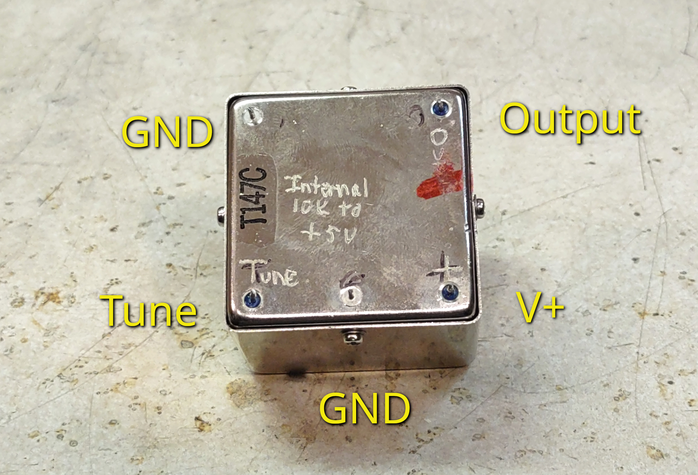
Figure 2:
The bottom of the OCXO, annotated to show the various
connections.
Click on the image for a larger version.

Using this device

In its original application, this device was powered from a 12-15 volt supply, but if you were to apply power and give it 5-15 minutes to warm up, you would probably be disappointed in its accuracy as it would not have any sort of external tuning input to get it anywhere close to its intended frequency.

Because of the need for it to be electrically tuned, this device is actually a VCXO (Voltage-Controlled Crystal Oscillator) as well and as such, it has a "Tune" pin, identified in Figure 2.  Nominally, the tuning voltage was probably between 0 and 10 volts, but unless a voltage is applied, this pin will naturally drift close to zero voltage, the result being that at 10 MHz, it may be a dozen or two Hz low in frequency.

Adding a resistor

The easiest "fix" for this - to make it operate "stand-alone" - is to apply a voltage on the pin.  If your plans include locking this to an external source - such as making your own GPSDO (GPS Disciplined Oscillator) then one simply need apply this tuning voltage from a DAC (Digital-to-Analog Converter) or filtered PWM output, but if you wish to use this oscillator in a stand-alone configuration - or even as an externally-tuned oscillator, a bit of modification is in order.

Figure 3:
This shows the 10k resistor added between the internal 5 volt
source and the "TUNE" pin to allow "standalone" operation.
Click on the image for a larger version.
The OCXO may be disassembled easily by removing the small screw on each side and carefully un-sticking the circuit board from the insulation inside.  Once this is done, you'll see that there are two boards:  The one on the top is part of the control board for the heater/oven while the bottom houses some of the oscillator components.

Contained within the OCXO is a 78L05 five-volt regulator which is used to provide a voltage reference for the oven and also likely used as a stable source of power for the oscillator - and we can use this to our advantage rather than need to regulate an external source which, itself, is going to be prone to thermal changes.

Figure 3 shows the addition of a single 10k resistor on the top board, connecting the "TUNE" pin to the output of this 5 volt regulator.  By adding this resistor, the TUNE pin allows one to use this OCXO in a "standalone" configuration with no connection to the "TUNE" pin as it is is automatically biased to a temperature-stable (after warm-up) internal voltage reference and can then be used as-is as a good 10 MHz reference, using the onboard multi-turn potentiometer to precisely set the frequency of operation.

Figure 4:
More pictures from inside the OCXO
Click on the image for a larger version.
Another advantage of adding the internal 10k resistor is that it's easy to reduce the TUNE sensitivity from an external voltage:  This value isn't critical, with anything from 1k to 100k likely being usable.  Testing shows that by itself, the oscillator is quite table and varying the TUNE voltage will adjust it by well over 10 Hz above and below 10 MHz.

The inclusion of the 10k internal resistor may also be of benefit.  In many cases, having a much narrower electronic tuning range than this will suffice so a resistor of 100k (or greater) can be used in series with the TUNE pin, between it and an external tuning voltage, acting as a voltage divider.  Doing this will reduce the tuning range and it can also improve overall stability since much of the tuning voltage will be based on the oscillator's already-stable 5 volt internal source.  The stability of the OCXO itself is such that even with a 10-ish:1 reduced tuning range due to a series 100k resistor, there is still far more external adjustment range than really necessary to tune the OCXO and handle a wide range of external temperatures.

The actual value of the added internal resistor is unimportant and could be selected for the desired tuning/voltage ratio based on the external series tuning resistor and the impedance of the tuning voltage.

When reassembling the OCXO, take care that the insulation inside the can is as it was at the time of disassembly to maximize thermal stability and, of course, be sure that the hole in the can lines up with the multi-turn potentiometer!

Operating conditions

Figure 5:
Even more pictures from inside the OCXO.
Click on the image for a larger version.
The "official" specifications of this OCXO are unknown, but long-term use has shown that it will operate nicely from 12-15 volts - and it will even operate from a 10 volt supply, although the reduced heater power at 10 volts causes warm-up to take longer and there may not be sufficient thermal input for the oven to maintain temperature at extremely low (<15F, <-9C) temperatures unless extra insulation is added (e.g. foam around the metal case.)

It is recommended that if one uses it stand-alone, the voltage source for this device be regulated:  While the on-board 5 volt regulator provides a stable reference without regard to the supply voltage, the amount of thermal input from the oven will change with voltage:  More power and faster heating at higher voltage.  While you might think that this wouldn't affect a closed-loop system, it actually does owing to internal thermal resistance and the fact that due to loss to the environment, there will always be a thermal gradient between the heater, the temperature-sensitive circuitry, and the outside world - and changing the operating voltage and thus the amount of heater power will subtly affect the frequency.

Finally, this oscillator - like any quartz crystal oscillator that you are likely to find - is slightly affected by gravity:  Changing orientation (e.g. turning sideways, upside-down, etc.) of this oscillator affects its absolute frequency by a few parts in 10E-8, so if you are interested in the absolute accuracy and stability, it's best to do the fine-tuning adjustment with it oriented in the same way that it will be used and keep it in that orientation.

* * * * * * * * *

This page stolen from ka7oei.blogspot.com

[End]


Tuesday, October 17, 2017

A 10 MHz OCXO (Oven-controlled Crystal Oscillator)

Figure 1:
The 10 MHz OCXO (lower right) in use with my homebrew
24 GHz transverter.  At 24 GHz, the oven provides excellent frequency
stability, suitable for SSB or even digital modes, while providing a
frequency uncertainty of a few hundred Hz at most.
Click on the image for a larger version.
Why a frequency reference?

When operating on the microwave amateur radio bands, narrowband modes (such as SSB or CW) are often used to maximize the link margin - that is, to be able to talk when signals are weak - and when we use microwave frequencies and narrowband modes such as SSB or CW one must maintain pretty good frequency stability and accuracy:
  • Stability is important as a drift of even a few hundred Hz at the operating frequency (in the GHz range!) can affect intelligibility of voice - or, if CW is being used for weak-signal work, such drifting can move the received signal outside the receiver's passband filter!  Having to "chase" the frequency around is not only distracting, but it complicates being able to communicate in the first place.
  • Accuracy is also important because it is important that both parties be confident that their operating frequencies are reasonably close.  If a contact is arranged beforehand it is vital that both parties be able to find each other simply by knowing the intended frequency of communication and as long as the two parties are within several hundred Hz of each other it is likely that they will be able to find each other if the path "works" in the first place.  If the error was on the order of several kHz, "hunting" would be required to find the signal and if those signals are weak, they may be missed entirely.
Because achieving such stability and accuracy requires some effort, it is more convenient if our gear is constructed such that it can use a common, external frequency reference and lock to it.  In that way, we need only have one "master" reference rather than several individual references.

Figure 2:
The 10 MHz Isotemp 134-10 OCXO - one of many similar units that
often show up on EvilBay.  A 200uF, 16 volt capacitor is soldered
directly to the supply terminals of the OCXO to provide low-impedance
filtering of any noise that might appear on it - any value from 2000 and
up (to several thousand uF) would be just fine.  The green device is a 10-turn
trimmer potentiometer soldered directly to the OCXO's pins.  This
potentiometer is used to adjust the tuning voltage to precisely set the
frequency and locating it at the OCXO practically eliminates the possibility
of external noise pick-up on the tuning lines and the possibility of the I*R
drop on the wires causing a slight tuning shift as the oven power changes.
The OCXO is mounted in the case using rubber/metal shock mounts with "blobs"
of RTV (silicone) on the sides that prevent it from hitting the inside of the box
should the unit be accidentally dropped.
The corners/edges of the OCXO could be mounted in some stiff foam,
instead - but it should not be thermally insulated by this foam unless you have
demonstrated to yourself that doing so will not reduce the oven's stability.
Click on the image for a larger version.
Having one common frequency reference can also be convenient if one is operating portable using battery power since it can mean that one doesn't need to keep all of those individual pieces of gear "warmed up" all of the time to maintain stability.  If a particular piece of gear can accept an external 10 MHz input, this would allow one to turn on that gear (and drain battery power) only when it is needed.

At this point I might mention that Rubidium frequency references (such as one described here) are also readily available in the surplus market as well that provide at least an order or magnitude greater accuracy and stability and warm up in less time than the crystal reference, so why not always use a Rubidium reference instead of a crystal-based one?  The crystal-based unit is cheaper, easier to package and consumes significantly less power than a Rubidium reference, and the stability/accuracy of a good-quality crystal-based reference is more than "good enough" through at least 24 GHz.  When I go out in the field to do portable microwave work I'll often power up the OCXO after putting it in the car knowing that by the time that I get to my destination and set up, it will be warm and on-frequency.  (To be sure, I bring a Rubidium reference as a "backup"!)

About this frequency reference:

The oscillator:


The goal for this project was to have a "reasonably stable and accurate" reference:  Based on an Isotemp OCXO 134-10 this particular unit has a rated stability of about +/-1.0x10-8 (+/-1 Hz at 100 MHz) or better after it has warmed up for a while with short term variations approaching +/-1.0x10-10 (+/-1 Hz at 10 GHz).  In-field observations appear to confirm this stability with tests having shown that this unit seems to be able to hold the 24 GHz local oscillator to within 500 Hz or better with no obvious frequency "warble" once it has had 15-20 minutes or so to warm up -  and it seems to be fairly stable across a range ambient temperatures from "hot" to "below freezing."  The Isotemp unit - and others like it - are readily available on both the new and surplus markets, available via EvilBay and similar and other than having different voltage and stability specifications, they, too, can be integrated into a stand-alone project such as this.

The oven module itself is rated to operate from 13 volts, +/- 2 volts, implying a minimum of 11.0 volts.  Even though testing indicated that it seemed to be "happy" with a supply voltage as low as 9.8 volts or so, it was decided to adhere to the published specifications and in looking around I noticed that most readily-available low-dropout regulators (and those that I had onhand) were not specified to handle the maximum "cold" current of this oven - about 800 mA - so I had to "roll my own" 11 volt "zero-dropout" regulator.  More on alternative regulators, below.
Figure 3:
The inside of the enclosure containing the OCXO, regulator and driver.
On the left is the shock-mounted OCXO while the circuit on the perfboard
is the "zero drop-out" regulator and the 10 MHz distribution amplifier.
The P-channel FET pass transistor can be seen along the top edge of
the die-cast enclosure, bolted to it to dissipate any heat while along
the right edge, inside the enclosure is a piece of glass-epoxy circuit
board material to provide a solid, solderable ground plane for the
distribution outputs and the DC input filtering.

A "zero-dropout" regulator:


Why regulate?  I noted in testing that slight variations of supply voltage (a few hundred millivolts) would cause measurable disturbances in the oscillator frequency due to the changes of the power applied to the heater, taking several minutes to again reach (thermal?) equilibrium.  Since battery operation was anticipated, it is expected that the supply voltage would change frequently between periods of transmit and receive - as well as due to normal battery discharge.  Because I had chosen to use an OCXO that required (at least) 11.0 volts to be run from a "12 volt" lead-acid battery, I needed a circuit that would reliably produce that 11.0 volts even when the battery voltage dipped below 11.5 volts - as it could during heavy transmit loads and the end of a power cable with the battery near the end of its charge.

Referring to the schematic U101, a standard 5 volt regulator (the lower-power 78L05 is a good choice) provides a stable voltage reference for U103, a 741 op amp, which is used as an error amplifier.  A 7805 was chosen as it is readily-available but a Zener diode and resistor could have been chosen:  If a Zener is used, a 5.6-6.2 volt unit is recommended with 2-5 milliamps of bias as this voltage range offers good temperature stability.

If the output voltage is too low, the voltage on pin 3 (the non-inverting input) drops, along with pin 6, the op amp's output which turns on Q103, a P-Channel power MOSFET by pulling it's gate toward ground, which increases the voltage and once the voltage on the wiper of R119 reaches 5 volts - that of the reference, which is applied to pin 2, the non-inverting input - the circuit comes to equilibrium.  A P-Channel FET (a slightly less-common device than an N-channel) was used because it takes 3-5 volts of drain-gate voltage to turn on a FET and it would have been necessary to have at least  3-5 volts above the power supply (about 16 volts) to bias the gate "on" if an N-Channel FET were used whereas we can pull the gate voltage "down" from the supply voltage with a P-channel device.  Furthermore, with the use of a P-Channel power MOSFET the dropout voltage of the regulator is essentially limited to the channel resistance of the that FET.  In theory a PNP (possibly a complimentary pair arrangement) could be used instead if one can tolerate closer to a volt of dropout, but the FET was chosen to minimize the dropout voltage.

In testing, once the oven was warm (a condition in which the OCXO was drawing approximately 250 mA at normal "room temperature") the dropout of the regulator was approximately 50 millivolts - a voltage drop that is a result of the resistance of the wires used to power the unit and the on-resistance of the FET.  This rather simple regulator seems to work quite well, holding the output voltage steady to within a few millivolts over the input voltage range of 11.1 to 17 volts with good transient response.
Figure 4:
The end panel of the OCXO module.  The power feedthrough/capacitor
is on the left, obscured by the red/white power cable with the yellow-ish
"ready" light to the right of it.  The three BNC connectors are the 10 MHz
outputs, allowing multiple devices to be connected while in use and/or while
its calibration is being checked.
Click on the image for a larger version.

"Faster warmup" feature:

This OCXO has a "status" output that, when "cold", outputs about 0 volts and in this state, Q101 is turned off, allowing R112 and R113/D102 to pull its collector high - turning on Q102 - which pulls the gate of Q103 low through R118, turning it fully "on."  In this state the voltage applied to the oven is nearly that of the battery supply and this higher voltage increases the power applied to the oven, allowing it to heat more quickly.  Once the oven's "status" line goes high, Q101 is turned on, illuminating the LED and turning off Q102, allowing the regulator to operate normally.

Note:  When the unit is warming up, the OCXO's voltage is unregulated which means that the supply should be kept below 15.0 volts to stay within the "safe zone" of the ratings of the oscillator itself.

Does the "boosted" voltage actually help the oven warm up faster?  Probably only a little bit, but it took only 4 additional components to add this feature!

Status indicator:

It should be noted that this status line doesn't indicate that the oven has fully warmed up, but only that it's still warming:  At "room temperature" it takes at least another 5 minutes before the frequency will be stable enough for use and another 5 minutes or so after that until it's "pretty close" to the intended frequency and it can be used at microwave frequencies without others having to chase you around.

Why have the indicator light if it doesn't indicate that the unit is actually "ready"?   While this indication isn't perfect if the light isn't on, you can be sure that the frequency output won't be valid for one reason or another.

Because the OCXO itself is somewhat load-sensitive (about +/-1.0x10-9 - perhaps a few 10s of Hz at 24 GHz) U102 - an LM7171 - is used as a distribution amplifier to both isolate the oven from its loads and to provide fan-out to allow multiple outputs to be driven simultaneously.  The LM7171, a high-output, high-speed op amp, is configured for a gain of 2, providing about 2 volts peak-to-peak output with the drive provided by the OCXO.

Mounting the oven:

Because this unit is intended to be used "in the field" it was decided to mount the OCXO module itself to prevent mechanical shock from affecting the reliability, frequency stability and accuracy and this was done using some rubberized mounting pillars from scrapped satellite equipment while some "blobs" of silicone were placed on the wall of the die-cast enclosure to prevent the OCXO housing itself from directly impacting it should the unit be accidentally dropped.

Figure 5:
Schematic of the OCXO-based unit, including the zero-dropout regulator and 10 MHz distribution amplifier.  It is important that the connection of the "ground" side of the 10 turn calibration potentiometer be made at the OCXO and not elsewhere, this to minimize possible frequency shifts due to I*R losses as the oven's heater power changes.  The diagram shows a
value of 82 ohms for R108-R110 because that what was easily found when it was constructed (and it really doesn't
matter much) but anything between 47 and 100 ohms will be fine, based on your preference.
Click on the image for a larger version.
A few bits of stiff foam could also be used to provide some shock mounting in the corners of the OCXO but be aware that some oven-based oscillators have been known to become less accurate and stable if they are over-insulated and can't radiate at least some of their heat, so don't go overboard.

Important:

Like any crystal oscillator, it is somewhat "position sensitive" in that a frequency shift of 10s of Hz (at 24 GHz) can be observed if the unit is placed on its side, upside-down, etc. due to the effect of gravity on the quartz crystal itself.  While this effect is very minor, it's worth noting when it's being set to frequency and in operation.

In other words, when you calibrate it (see below) do so in the same physical orientation that it will be when it is in use.

DC input protection and filtering:

The input supply is RF-bypassed using a feedthrough capacitor to prevent the ingress or egress of extraneous RF along the power lead.   For power-supply short-circuit and reverse-polarity protection, R101, a 1.1 amp, self-resetting PTC fuse is used in conjunction with D101, a 3-amp diode.

Why not use a forward-biased diode for reverse-polarity protection?  If you recall, we are going through the trouble of minimizing voltage drop-out with our "special" voltage regulator and we could diminish this if we inserted something that caused a voltage drop - even the 0.3-ish volts of a Shottky diode would undermine this effort.

By using the "reverse-biased diode" and the self-resetting PTC fuse we get:
  • A means of current limiting should something to wrong:  If we accidentally short something out, the fuse resets itself when the fault is cleared - and no need to worry about not having a spare fuse when one is out in the hinterland trying to operate!
  • If the polarity is somehow connected backwards, the diode will conduct and the PTC fuse will "open" - no harm done, returning to normal once the fault is rectified.
  • There is minimal voltage drop related to the fuse as its resistance is a fraction of an Ohm under normal conditions which means that we won't compromise the voltage "headroom" of a 12-volt lead-acid battery.
Calibration:

The best way to calibrate this device is to use a GPS disciplined oscillator or a known-good rubidium frequency reference.  If you have access to one of these, connect the output of the OCXO to one channel of a dual-trace oscilloscope and the known-good frequency reference to the other, triggering on one of two signals - it really doesn't matter which one.

Note:  If you have an analog dual-trace oscilloscope with sufficient bandwidth you can use the "X/Y" mode to produce a Lissajous pattern (obligatory Wikipedia reference here) - but this doesn't always work well on modern, digital scopes when high frequencies are involved due to sample aliasing.

Adjusting the 'scope to see one of the waveforms, one should see a stationary wave (the one on which the 'scope is triggered) while the other will be "sliding" past the first.  Adjust the OCXO's frequency (after the OCXO has warmed up for at least 30 minutes - preferably more) while it is sitting in the same physical orientation in which it will be used as this can (slightly) affect frequency.  To assure a more consistent thermal environment it is suggested that the cover of the enclosure containing this circuitry be left on except during the brief periods to access the 10-turn potentiometer unless provisions are made to access it (via a hole) from outside the box.

The OCXO's frequency is then adjusted to minimize the rate at which the two waveforms are moving with respect to each other:  It's sometimes easier to make this adjustment if the 'scope is adjusted so that the two waves are atop each other and about the same size.  With careful adjustment it should be possible to set the frequency so that the two waveforms that take more than 10 seconds to "slide" past each other - maybe longer.  The Isotemp OCXO should, in theory, be able to hold to that "10 second" slide rate over a wide variety of temperature conditions.

If you don't happen to have access to a rubidium reference or a GPS Disciplined oscillator, you can do "reasonably" well by zero-beating the 10 MHz output with the signal from WWV or WWVH, be note that Doppler shifts can cause their apparent frequencies to shift by 1 Hz or more.  I'll leave the explanation of methods of successfully zero-beating an off-air signal to others on the GoogleWeb.

The best time to attempt this is when you are hearing only one of these two stations (assuming that you can ever hear them both) and when it's signal is the most "solid" - that is, it's fading in and out is at minimum.  Often, the worst time to make this sort of measurement is when any part of the radio path between you and WWV (or WWVH) is within a hour or two of sunrise or sunset as this is when the ionospheric layers are in a state of flux.  If you are hearing both WWV and WWVH, don't try this as the two frequencies and signal strength will not likely be consistent and the results will probably be confusing.

If you don't happen to live in an area where you have a reasonable signal from WWV or WWVH then I suggest you ask around to find someone who has appropriate gear to help with this task.

Comments about alternative schemes for low-dropout regulation for the OCXO:

There are a number of "low-dropout" adjustable regulator ICs on the market that may be suitable for your this project - but there are a few caveats.

For example, there is the Linear Technologies LT1086-Adj which is rated for up to 1.5 amps of current.  While lower dropout than a conventional adjustable regulator such as an LM317, it does have approximately 1 volt of dropout which means that if you set the OCXO's supply voltage to 11.0 volts - the minimum recommended in the OCXO's specification - your battery voltage must be at least 12.0 volts:  While this represents a lead-acid battery that mostly depleted it is likely that a small, but healthy, lead acid could drop to such a voltage under transmit load - particularly if the resistance of power leads is taken into account.  This 3-terminal regulator is used in a manner very similar to the LM317 - except that you really must have some good quality, low-ESR capacitors (probably tantalum) very close to the regulator itself - see the data sheet.

Also made by Linear Technologies is the LT1528 that is rated for up to 3 amps that has a (nominal) 0.6 volts of dropout - more typically in the 0.3 to 0.5 volt area for the amount of current consumed by the OCXO, particularly once it has warmed up:  This extra margin would keep one in the "safe" region of the OCXO's operating voltage range down to around 11.5 volts from the batter allowing both "deeper" discharge and more voltage drop on connecting wires.  This part is somewhat more complicated to use than the LT1086, above, but it is, overall, simpler than the op-amp based regulator described earlier in this page.

If the "fast warmup" were to be implemented on either of the above regulators it would take a different form than the above - likely using several resistors and a transistor or two to "switch" the resistor-programmed voltage setting to something higher than the normal voltage.

There are a number of other, similar, low-dropout regulators that are made by different manufacturers, but very few have as low a dropout voltage (e.g. about 50 millivolts) as the simple FET/Op-amp circuit described on this page.

Additional comments:
  • It is recommended that one not use a switching regulator to power the OCXO unless it has been extremely well filtered and bypassed.  Unless such a regulator is a buck-boost type it will probably have a higher drop-out voltage than even a standard low-dropout linear regulator.  Because of the rather low overhead voltage involved, there is not much loss in the linear regulator - only 10-15% or so with a 12.5 volt supply with a 11.0 volt output - a loss comparable to a garden-variety switching regulator.
  • If you are interested in an example of this project being built with an etched PC board with surface-mount parts, visit VK4ABC's 10 MHz OCXO Web Page.

* * *

This is a revised version of one of my web pages, the original being found at http://www.ka7oei.com/10gig/10meg_oven_1.html


[END]

This page stolen from ka7oei.blogspot.com

 Note:  This post is partially an attempt to test means of reducing the "scraping" of content of this blog by sites such as "rssing", who seem to "swipe" content and "load" search engines' result with unwary readers NOT ending up at my page.     xe2XV6SJ9914C50H08S8  QY2IU7TU0C11c57804Q8

xe2XV6SJ9914C50H08S8 QY2IU7TU0C11c57804Q8


Friday, March 31, 2017

A (somewhat convoluted) means of locking a "binary" (2^n Hz) frequency to a 10 MHz reference

DDS (Direct Digital Synthesis) chips are common these days with small boards containing an Analog Devices AD9850 board being available on EvilBay for a cost lower than one is likely able to buy the chip by itself!  While these boards are quite neat, they do have a problem (or quirk) in that you are not likely to be able to generate the exact frequency that you want - at least if it is to be an exact integer of Hz.

Let us take as an example one of those ADS9850 DDS boards available on EvilBay.  These come equipped with a 125 MHz crystal oscillator that will likely be within 10-20 ppm or so, but let us assume that it is exactly 125 MHz.

Other than the 125 MHz clock and some output filtering, the AD9850 DDS chip has nearly everything else that one would need to generate an output from DC to around 60 MHz - the precise limit depending on filtering - and its frequency is set using a 32 bit "tuning word".  The combination of the 125 MHz clock and the 32 bit tuning word means that our frequency resolution is:
  • 125,000,000 / (232) = 125,000,000 / 4,294,967,296 = 0.02910383045673370361328125... Hz per step - approximately.
For most purposes around 1/34th of a Hz resolution would seem to be good enough - and it probably is - but what if you wanted to be able to generate frequencies that were exact multiples of 1 Hz steps for frequency comparison purposes or to be able to generate precise, standard frequencies like 1, 5, 10 MHz, etc. - or even a very precise 1 kHz tone?

The quick answer to this is to pick a clock frequency that is an exact "power of two" Hz, and the closest 2n multiple to 125 MHz is 227 or 134.217728... MHz - slightly beyond the ratings of the AD9850, but it is likely to work.  (Depending on the high frequency requirements, half of this frequency - 226 Hz, or 65.108864 MHz might be used instead:  Other frequencies that are 2n divided by an integer such as 2n/10 are usable, too as an example.)

What does this change in clock frequency gain for us, then?
  • 227 / 232 = 0.03125 Hz per step, which is exactly 1/32nd Hz.
In this way, very precise frequencies that are a multiple of 1 Hz (and a half-Hertz as well) could be produced.

(Where does one get a 134.217728 or 65.108864 MHz oscillator?  This would likely require a custom-made crystal/oscillator or it could be produced using another synthesizer such as an SI5351A that, itself, uses a VCXO as its reference.)
Locking the DDS synthesizer to a 10 MHz frequency reference

It would make sense that if you actually needed to be able to set your frequency to exact 1 Hz multiples that you would also need to precisely control the reference frequency as well - likely with a 10 MHz precise reference from a GPS Disciplined Oscillator (GPSDO), a Rubium frequency reference or something similar.  Unfortunately, 227Hz is an awkward number that doesn't easily relate to a 10 MHz reference.

The most obvious way to do this is to use a second DDS generator board (they are cheap enough!) clocked from the same 227Hz source with its output to exactly 10 MHz using a frequency word of 320,000,000d, comparing it to the local standard and applying frequency corrections to (e.g. shift slightly) the actual frequency of the "227Hz" oscillator.

There is a less-obvious way to do this as well, so here is an example using 224 Hz - which is 16.777216 MHz:

For the 10 MHz chain:
  • Take the 10 MHz output and divide it by 625 to yield 16.000 kHz
  • Multiply the 16.000 kHz by 32 to yield 512.000 kHz
  • Divide 512 kHz by 125 to yield 4096 Hz
For the  2n Hz chain:
  • Divide any 2n Hz frequency down to 4096 Hz as a basis of comparison.  For 224 Hz we would divide-by 4096 using a binary divider.
(Depending on one's requirements, the precise method could vary with other frequency combinations possible.  The frequency of 512kHz was used because it was well within the operational range of good, old-fashioned 4000 series CMOS circuitry.)

Why would anyone use this second method?  Back in the 1980s I built a DDS synthesizer that used a 224 Hz reference (16.777216 MHz) that used a 24-bit tuning word to provide precise 1 Hz steps, but I also needed to lock that same synthesizer to a high-quality 10 MHz TCXO.  While it would have been possible to have built another synthesizer, a 1980s solution to this problem meant that an entire synthesizer circuit (or most of it, anyway) consisting of more than a dozen chips - some of them rather expensive - would have have to be replicated to do this one thing.

This seemingly convoluted solution required required only 6 inexpensive chips - a combination of 74HC (or LS-TTL) and some 4000 series CMOS devices.  For example:
  • Dividing the 10 MHz reference by 625:  A 74HC40103 wired as a divide-by-125 followed by a 4017 counter wired as a divide-by-5 to yield 16 kHz.
  • The multiplication of 16 kHz by 32 to 512 kHz:  A 4046 PLL and a 4040 counter wired as a divide-by-32 to form a synthesizer.
  • Division of 512 kHz to 4096 Hz:  Another 40103 wired as a divide-by-125.
  • Division of 16.777216 MHz down to 4096 Hz:  A 74HC4040 counter dividing by 4096.
The final step to lock the two frequency sources together was to use the venerable 4046 phase detector, outputting the correction voltage to the 16.777216 MHz oscillator.

A comment about using the 4046 PLL chip:

It's worth noting that because the 4096 Hz output from the divide-by-125 from the 512kHz source is a pulse rather than a square wave so it is not possible to use the "XOR" phase detector (Phase detector 1) of the 40406, but rather the flip-flip detector (Phase detector 2).  The "problem" with the flip-flop detector is that when the two frequencies are close, instead of having a constant train of pulses being output that are either at the reference frequency or twice the reference frequency, one will get occasional, brief pulses as the output of one of the flip-flops occasionally drops out of its high-impedance mode.

The problem with is that these occur (more or less) randomly and comparatively rarely, meaning that they they are at a rather low frequency and can get through the loop filter, causing extra jitter on the locked frequency - the 16.777216 MHz oscillator in this case.  The "fix" for this is to slightly bias the output of the phase comparator toward V+ or ground with a high-value resistor (100k-4.7 Meg, depending on the application) which will "pull" the output constantly toward one rail, forcing the loop to be corrected constantly meaning that instead of the occasional, narrow pulse, there will always be a string of pulses at a "high-ish" frequency that can be removed by the loop filter.  With the rather low "loop gain" of this VXCO configuration, "jitter" caused by the multiplication synthesis and divisions really doesn't show up in the 224 Hz crystal oscillator being locked.

Even though the 4046 CMOS with its built-in oscillator and phase/frequency detector is a bit "jittery", remember that this is being applied with a slow loop filter to a VCXO circuit with very low overall loop gain so this jitter averages out nicely.

(There are a number of modern phase/frequency detector chips that do not have this "jitter" problem.)
With the main 16.777216 MHz reference being a VCXO (Voltage-Controlled Crystal Oscillator) the above scheme worked very well, locking to the 10 MHz reference in a second or two.  Back in the 1980s the most accurate frequency reference that I had was a collection of OCXOs (Oven-Controlled Crystal Oscillators) and TCXOs (Temperature-Controlled Crystal Oscillators) with the 10 MHz units being easily referenced to the off-air signal from WWV to provide both an accuracy and stability of around one part in 107 or better.  Because, in our example, we are starting out at a much higher frequency (e.g. 134-ish MHz) we might divide this down to 4096 Hz - or whatever frequency our implementation required - using a combination of 74F or 74Axx logic and a (74HC)4040 counter.

(If our 134-ish MHz clock were produced using an SI5351A synthesizer, the PLL corrections in this scheme would be applied to its clock, which typically operates at around 27 MHz.)

Nowadays, with GPSDOs and second-hand rubidium references being affordable, the accuracy and stability can be improved by several orders of magnitude beyond that of the TCXO that I used those many years ago.

Having said all of this the question must be asked:  Is any of this still useful?

You never know!


[End]

This page stolen from ka7oei.blogspot.com
 

Monday, August 31, 2015

A PIC-based audio source for locking a VHF oscillator

Several years ago I decided to build a weather satellite receiver from scratch.  It is described here - link.

I didn't really need a weather satellite receiver, and I could have easily bought a kit somewhere else - or bought a second-hand one via EvilBay, but I just wanted to go through the exercise of throwing everything together and making it work using parts on hand - and I wanted to try out some ideas.

Locking a VCO to an audio DDS reference:
Figure 1:
The front panel of the VHF weather satellite receiver.
This receiver has been in continuous operation for several years, working
flawlessly in that time.
Click on the image for a larger version.

One of these ideas was to use a PIC to lock the VHF local oscillator.  On the face of it, this isn't unique - except that the PIC was to be the sole source of the precise frequency to which the PLL (Phase Locked Loop) for the local oscillator:  No divide-by-N chips here!

For this receiver the local oscillator operated 10.7 MHz below the receive frequency nominally at about 126 MHz.  Since I was already using a 100 MHz oscillator (a VCXO) that I'd pulled from some scrapped commercial satellite gear, I used a simple 3-transistor mixer/amplifier circuit to convert this to about 26 MHz (137 MHz-10.7 MHz-100 MHz) and this allowed me to use a 74HC4040 12-stage binary ripple counter to bring a representation of the local oscillator down to the audio range - about 6.3 kHz.

As it so-happened, I'd chosen the 100 MHz oscillator on purpose - mostly because it was free, but it also provided a nice, stable 20 MHz clock for the PIC by dividing its output by 5 using a 74F191 so both the down-conversion and the PIC's clock were referenced from the same source.

The goal was to provide a minimum tuning step size of at least 1 kHz, and because I'd already divided the local oscillator by 4096 this meant that my audio-frequency step size was on the order of 1/4 of one Hz - but that was no problem since I was going to use DDS techniques in the PIC.

The DDS:

A DDS (Direct Digital Synthesis - see the Wikipedia article about DDS techniques here - link) is fairly simple in operation:  Typically, one takes a register (called an "accumulator") and on every clock cycle you add to it a constant number (we'll call it a "frequency word") allowing it to "wrap around" once the accumulator's capacity is exceeded or, in other words, you do unsigned binary addition.

If you were to keep track of how often the accumulator overflows you'd notice that if you added a smaller number to it, it would overflow less often which makes sense since it would take more clock cycles to overflow!  What you might notice is that one can easily predict the rate at which it will overflow:

( (frequency word) / (maximum accumulator value) ) * clock frequency

Typically, the "maximum accumulator value" is the maximum number (plus one) that can be represented by the number of bits used by the accumulator (e.g. 8 bits = 256, 16 bits = 65536, 32 bits = 4294967296).

In my case, it was easy to make the PIC do 32 bit unsigned addition.

The last step is to take the upper-most bits of the accumulator and apply them to a D/A converter via a sine-wave lookup table.  To take a table that is "8 bits" in size (256 entries) one would take the top byte of our exemplar 32 bit accumulator, use those bits to point to a sine wave and then send the output of that sine wave lookup to the D/A converter.  Clearly, the more bits of lookup (e.g. the larger the sine wave table) and the more resolution that one has available for the D/A converter, the better!

Figure 2:
The PIC controller board that generates the precise audio frequency
based on a PIC16F88 and driven from a 20 MHz clock source.  This PIC
also drives the LCD and does the serial data communications,
receiving frequency tuning commands from the host computer.
Click on the image for a larger version.

Hardware:

The PIC that I used (a PIC16F88) can be clocked to 20 MHz and among other things it contains a PWM generator that can operate as a simple D/A (Digital-to-Analog) converter with as much as 10 bits of resolution.  As such, it has a 10-bit timer and with the PWM operating at (up to) 10 bits of resolution it will sample at up to 1/1024th of the clock frequency, or:

20 MHz / 1024 = 19.53125 kHz

Since we have 232 (4 billion+) counts in our 32 bit accumulator, and we clock it at as high as 19.53125 kHz, that means that our frequency resolution is about one four-billionth of 19.53125, or:

19.53125 kHz / (232) = 0.000004547 Hz - or about one five-millionths of one Hertz resolution!

There's one more step in generating a useful frequency output.  If one watches the MSB (most-significant bit) of the accumulator, we can see that it flips between 0 and 1 at the desired frequency, but we don't want a digital output:  Even if we did take the MSB which is, on average, at the desired frequency, it typically has a lot of phase jitter that makes it unsuitable for most frequency control purposes.

If, instead, as noted above, we take the top several bits of the accumulator and feed them to a lookup table that has a sine wave and then outputting that value to a D/A converter, we get a more analog-looking signal with much less phase jitter:  The more bits we have, the better job we can do in representing a sine wave.

Now, remember that we divided our mixed-down local oscillator by 4096, so this means that our effective resolution would be reduced by that much, but if you do the math, that still means that we have - when multiplied by 4096 - a step size of 0.0186 Hz or so at the VHF LO frequency!

If you've been following along, you might noticed that I skipped several steps, so let me explain:

The idea was to divide down a representation of the 126 MHz local oscillator to audio and we did this by first subtracting 100 MHz from it and then dividing-down the 26 MHz by 4096 to audio.  We would then generate a precise audio frequency at one-4096th of that 26 MHz frequency and using a PLL, lock our local oscillator to it!

Simple - almost.

The DDS technique is imperfect when implemented using hardware that doesn't have infinite resolution - and the PIC's hardware and software capabilities are rather limited - in my case, I managed to implement the equivalent of a 1 "ksample" sine wave with 10 bits of resolution.  (Actually, it was just 1/4th of a sine wave - which is enough if you flip the pieces upside-down and/or play it backwards in the right order as needed!)

So now I had a precision audio generator that could output a reasonable facsimile of a sine wave at any frequency from about 5 milliHertz (including DC, if you want to be pedantic) to something less than 1/2 of the sample rate - about 9 kHz!  The PWM output from the PIC is really a bunch of samples of a 19 kHz variable duty-cycle digital waveform and it needed to be filtered a bit so I ran it through a simple op-amp bandpass filter - and then converted it back into a square wave - before passing it on to the a 4046 chip and into the edge-triggered phase detector.  In the 4046 this was compared with the converted/divided signal from my local oscillator and with the magic of the PLL, my VHF oscillator was nicely locked to the precise audio frequency from the PIC!

Almost...

At this point, the imperfection of the DDS became apparent.

One of the satellite frequencies is 137.62 MHz with a local oscillator frequency of 26.92 MHz.  When this was divided by 4096, this yielded a frequency of 6.5723 kHz approximately.

If one takes a close look at the spectrum produced by any DDS-type synthesizer, a myriad of low-level (and some not-so-low-level) spurious signals will be generated because of rounding-off errors related to the finite resolution of the D/A converter, the size of the sine table, and the relationship between the desired frequency and the clock frequency.  As one approaches frequencies that are related to an integer sub-multiple of the higher order bits (e.g. multiples of 1/2, n/4, n/8, n/16, n/32, n/64, etc. of the clock frequency) these low-level spurs get closer and closer to those multiples mentioned above.  As these sub-multiples get "smaller", the amplitude of these spurious components decrease as well.

In the case of the 6.5723 kHz signal required to synthesize 137.62 MHz frequency, this was very close to 43/128ths of the clock frequency - or about 10.986 Hz off.  What this caused was a very low-level 11-ish Hz modulation of the generated frequency which, when effectively multiplied upwards by the 4096 division - which increased the apparent loop gain - appeared as a very obvious tone (more of a buzz, actually!) at the local oscillator frequency.

Normally, loop filtering would take care of this, but this rather low frequency (just 11 Hz!) could get through the filter too well - and further-slowing of the loop filter wasn't particularly attractive - but this is software and we can do sleight-of-hand to fix this!  What I did was to pick a slightly different clock frequency - 20 MHz / 896 = 22.32142857... kHz instead and this moved the spurious signals from the DDS far enough away that they were effectively removed by the loop filtering.

The end result was a VCO that would tune anywhere within the designed range in less than a second and have very low-level spurious signal content from the DDS!

Locking a VCXO to an audio DDS reference:

As it turns out, locking a VCO - essentially a free-running oscillator with an implied, wide tuning range - is a comparatively "worst-case" scenario when it comes to the minimization of things like "reference sidebands" - the frequency/phase modulation of the generated carrier from residual AC on the tuning line - owing to the very high loop gain involved which can arise from both the "tuning sensitivity" of the VCO itself and if high divisor ratios are used.  If one starts out with an oscillator with a comparatively narrow tuning range - such as a VCXO (Voltage Controlled Crystal Oscillator) - in which the tuning sensitivity can be orders of magnitude smaller - and the lock time may be longer, particularly if high divisor ratios are used since it may take some time for the phase fo the comparison signal to "slide" into alignment - it is much easier to keep those already low-level spurious signals down to levels that may be ignored in typical applications.

A practical implementation of this technique has been employed in the W7SP Synchronous/Voting repeater system operated by the Utah Amateur Radio Club (described here - link) in which the transmit frequency is referenced from 10 MHz OCXOs (Oven Controlled Crystal Oscillators) and held within 1-2 Hz of the intended frequency.  Using DDS techniques with 32 bit accumulators operating at approximately 3.2 kHz, the transmit frequency can be controlled - via the audio frequency - to a resolution of 0.0023 Hz at the two meter transmit frequency - an accuracy that far exceeds the accuracy and stability of the reference oscillators themselves!

Producing exact frequencies:

The difficulty with using DDS techniques arises when an exact frequency is desired, such as for a frequency standard - at least unless one is willing to crunch a few numbers and/or make a few compromises.  For example, since the typical DDS algorithm is based on binary counters and thus has denominators of 2n power, one will likely not end up with the precise frequency desired.  In our example, above, with a 32 bit counter, we can likely get the frequency to with a fraction of a Hertz, but not exactly where it should be.

There are several ways around this, including one or more of the following:
  • Extending the resolution of the binary counter used in the DDS with even more bits to get ridiculous resolution so that the resulting frequency is "good enough."  If enough processor time is available and 32 bits of resolution is not enough, 48 or even 64 bits of addition may be implemented to do unsigned math.
  • The careful selection of a clock frequency such that the divisors result in the exact frequency desired.  The difficulty here is that if it is an "exact" frequency that is desired, many reference frequencies - such as 10 MHz - are not "binary friendly", requiring a bit of clever math to come up with exact relationships with the target frequency.
  • Designing the DDS counter to use something other than a binary (2n) counter.  If, say, a 10 MHz clock is used, the software DDS may be implemented using counters that will roll over at 10n instead of 2n, driven by a hardware divisor set to a base-10 relatable value to yield exact frequencies.
  • Implementing "dithering" of the DDS count to achieve fractional tuning.  This involves switching between two or more frequencies at a specific rate to achieve a third, averaged frequency.

 The last method, dithering, must be used with care as it will, by its nature, introduce spectral components that are necessarily lower in frequency than that of the reference being generated by the DDS - possibly very much lower if the fraction being represented by the dithering is complex - and these lower frequencies can greatly complicate effective loop filtering!  In most cases it would be more beneficial to simply extend the resolution of the software DDS (e.g. more bits) rather than implement dithering making this technique most useful if one us using a hardware-based DDS.

Comment:
If one needed to provide exactly 1 Hz steps, a DDS reference frequency based on 2^n Hz would be appropriate.  For example, if you chose 2^24 Hz (16.777216 MHz) you can lock that (awkward) frequency to 10 MHz as follows using only a few chips:
  • Divide 10 MHz by 625 to obtain 16 kHz (using a 74HC103 as a divide-by-125 and a 4017 to further divide-by-five.)
  • Using a PLL, multiply 16 kHz by 32 to yield 512 kHz (the lowly 4046 and a 4040 binary counter work well for this.)
  • Divide 512 kHz by 125 to yield 4096 Hz (using another 74HC103 to divide by 125)
  • Divide the 16.777216 MHz DDS reference oscillator by 4096 using a binary counter to 4096 Hz for the frequency comparison (a 74HC4040 works well as the divider here.)
The above steps may be done many different ways to get different frequencies, but the above is one example as to how to tie the two disparate frequency references together.

Final thoughts:

While there are definite limitations in using a DDS reference to lock a high frequency oscillator, namely the need to suppress the inevitable reference sidebands that result from the DDS synthesis itself by filtering, careful selection of reference frequencies and/or choice of the type of oscillator, but appropriate application of these methods can produce a reliable, versatile - even simple - frequency source.

[End]

This page stolen from "ka7oei.blogspot.com".