Showing posts with label TCXO. Show all posts

Monday, November 25, 2024

The "Universal TCXO" - better stability for the Kenwood TS-590, TS-570, TS-480 (and other radios) using the QRP Labs ProgRock 2

Figure 1:
The TS-590G into which the ProgRock was installed.
A useful accessory for many amateur transceivers is a TCXO - a device, often offered as an option, that improves the absolute frequency stability and accuracy of the radio.  When in current production, the TCXO is available from the manufacturer - and possibly from third parties - but long after the radio has been made, a TCXO may be difficult to find.

One option for addressing this issue is the use of the QRP Labs ProgRock 2 - LINK.  This unit is relatively inexpensive (US$18 at the time of writing) and has a stability of 0.25ppm - which is likely better than the original TCXO offered by the manufacturer - and likely less expensive as well.

This page describes not only the installation of the ProgRock 2 in a Kenwood TS-590, but also in the TS-570:  These two radios use very different frequencies, but the ProgRock 2 is easily programmed to whatever is needed!

Any weird frequency

Square waves are OK
 
The ProgRock 2 produces a square wave output, rich in (odd-order) harmonics - but is this OK for use in a radio?
 
It should come as no surprise that modern radios use the reference oscillator - the function being provided by a TCXO - as the basis for timing (possibly) every other frequency-determining module - and this is done digitally.  Somewhere along the line, the signal being output by the reference oscillator - whether it's a TCXO, an ordinary crystal oscillator or even the ProgRock - will be converted to a digital signal, anyway.
 
In many cases, the TCXO - if not the original oscillator - already produces a square wave which means that the rest of the circuitry is, by default, happy with the square wave output from the ProgRock 2.

While not directly applicable here, if a square wave were fed to circuitry via, say, a long, poorly-terminated coaxial cable, the square wave might get badly distorted and the circuitry in the radio may not be able to properly trigger on it - but since the ProgRock's output is being fed directly into the radios circuitry, this is not going to be a problem.

While it would be convenient if radios had a nice, easy frequency like 10 MHz as their main oscillator, that is rarely the case - and this was true for a friend's TS-590G which wanted 15.6 MHz.  This radio, which he purchased second-hand, did not come with a TCXO and based on his experience during June Field Day and winter Field Day (in January) it drifted excessively - more than a few 10s of Hz on 10 meters - enough that he would occasionally get complaints about him being "off frequency" - even if it was he that was calling CQ!

Although an aftermarket unit was available, he was intrigued by the idea of using the ProgRock 2 as this same device could be programmed for any frequency between about 3.5 kHz and somewhere near 300 MHz with a resolution of 1 Hz.  Additionally, the ProgRock 2 allows the use of a 1 PPS (1 pulse-per-second) output from a GPS module to "discipline" the oscillator with even greater stability - but more on this later.

Prepping the ProgRock 2

Using the ProgRock 2 is pretty easy:  It has a micro-USB connector onboard and when plugged into a computer, it can appear as a serial port - refer to the manual for the appropriate driver.  Using a serial terminal program - like PUTTY - one simply enters the frequency, to the nearest 1 Hz, hit the "S" key to save it to memory and you are pretty much done.  The ProgRock will allow the output of more than one frequency if needed (the manual has more detail) but we will be using output #1, which is also the one into which we'd program the needed frequency, setting the others to zero (e.g. "off").

Figure 2:
ProgRock 2 with the 3.9 and 10k resistors mounted to allow
the external application of a 1pps signal from a GPS module
to stabilize the frequency further.  The bottom side of the
ProgRock 2 is shown.
Click on the image for a larger version.

Having said that, there's a bit more to it in that it needs power, ground, and the signal output needs to get into the radio - but more on that in a moment.  

As my friend wished to experiment with using a 1 PPS source to nail it down to frequency, a 3.9k series resistor was added to the "1pps" pin along with a 10k resistor to ground to keep the pin from "floating" around in voltage when nothing was connected to it.  Figure 2 shows these resistors mounted on the "bottom" side of the board:  The upper resistor is the 3.9k connected to the 1pps pad with the lower, 10k resistor connected to a ground pad.  The junction of the two (with the yellow piece of insulating tubing) is where the 1pps input would be connected.

The use of the 3.9k resistor is described in the ProgRock 2's documentation which notes that the onboard microcontroller operates from 3.3 volts - but placing this resistor in series (the value of which isn't particularly critical) limits the current into the logic pin, allowing it to be safely driven by a 5 volt - or even 12 volt - 1pps pulse. 

Figure 3:
The Progrock 2 mounted to the original TS-590 TCXO board
using short, insulated jumper wires.  The top side of the
ProgRock 2 is shown.
Click on the image for a larger version.
As noted in the ProgRock 2's documentation, as long as the 1pps pin is held low, it's ignored and the unit will operate based on the frequency set by its onboard oscillator, but when it sees the 1pps pulses, it measures the time between their rising edges to determine how far off the internal clock is from ideal, making slow, incremental changes.  If the 1pps signal were to later disappear, it would simply "hold" that frequency until the ProgRock 2 was power-cycled at which point it would revert to the internal clock unless/until it was again presented with a 1pps signal.

There's a place for it!

While the "stock" TS-590 did not come with a TCXO, there was a small "daughter" board adjacent to the portion of the circuit board with the stock oscillator on which the user is expected to solder a TCXO in the form of a "crystal can" oscillator module - or, in the case of some after-market units - replace that board entirely.  As the ProgRock 2 is roughly the size of a postage stamp (it will fit within an HC-6 crystal can!) it could be wedged on this same board - which is convenient as this board also carries 5 volt power for the original TCXO, so a bit of pretty easy "micro" surgery was undertaken.
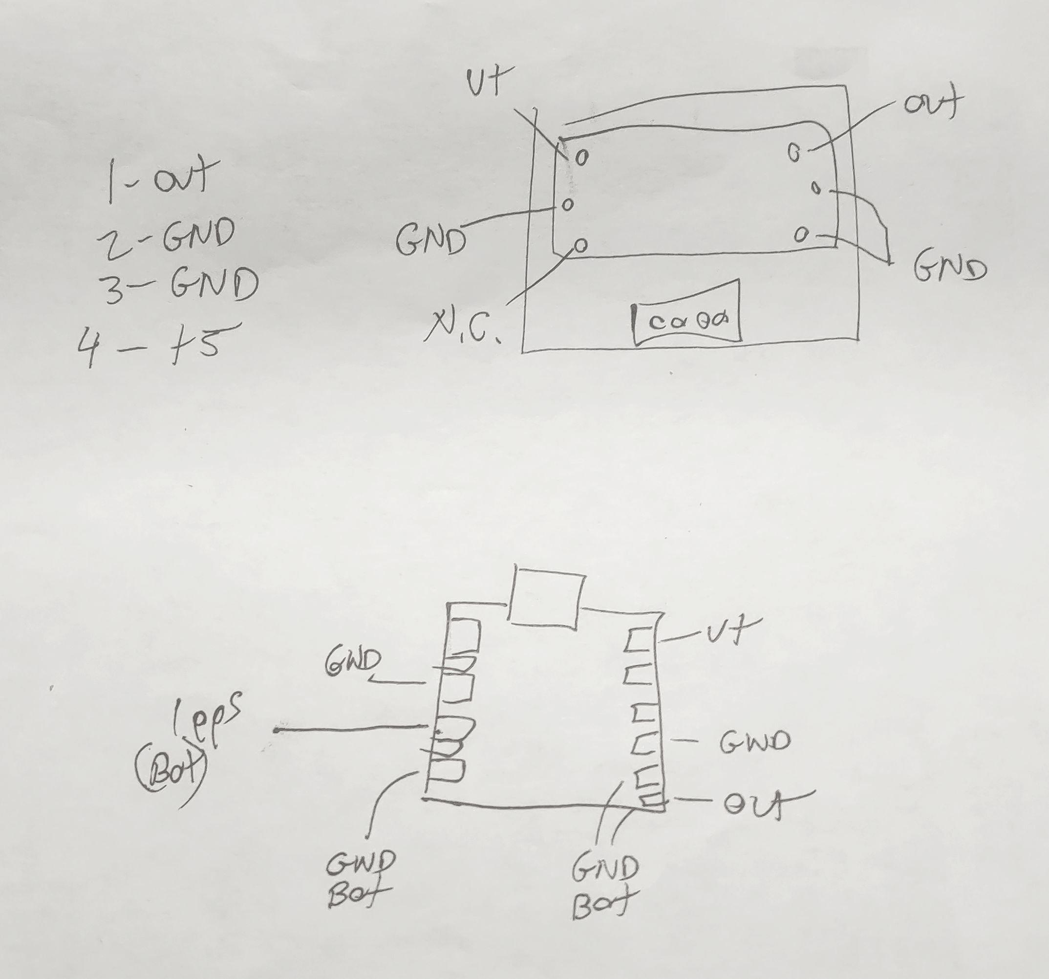
Figure 4:
A hand-drawn diagram showing the connections
on the top side of the TS-590's TCXO board and
the ProgRock 2 board.
Click on the image for a larger version.

Figure 3 shows how the ProgRock 2 board was mounted on the original TCXO board.  Fortunately, all of the needed connections are there:  +5 volts to run the original TCXO, ground, and the signal output.  Figure 4 shows a hand-drawn diagram showing the original TCXO board (top) with its pin locations while a representation of the ProgRock board (with the USB connector oriented on top) is in the lower drawing along with its connections.

Using small gauge, insulated wire liberated from a scrap of CAT5 Ethernet cable, short-as-possible jumpers were run between the TCXO board and the ProgRock.  In Figure 3, the "ground" connections were made using green wire - one of them utilizing the body of the USB connector - while the output signal used blue and the power used orange:  In the upper-right corner of the ProgRock 2 board - just above the USB connector - you can just see the yellow insulating tubing of the 1pps connection.

There is JUST enough room - if one scrunches the edge of the ProgRock 2 board against the TCXO board's white connector (and by routing wires such that they are not between the ProgRock 2 board and the connector) so that it will fit in the original location within the TS-590 as can be seen in Figure 5, below.

Comment:

It was noted - during testing of the TS-590 - that  the combination of 10 meters at 100 watts while using the built-in tuner - seemed to "glitch" the ProgRock for reasons unknown, although it's suspected that magnetic fields from the PA/Tuner board are finding their way through the aluminum chassis from the opposite side.  Simply tipping the ProgRock 2 board from being flat against the original TCXO board to more of an angle and adding another ground wire jumper to the TCXO board seemed to fix this.

One important consideration is that you MUST be sure that there's a blocking capacitor somewhere between the output of the ProgRock 2 and the input of the circuit that it's driving.  As it turns out, the stock TS-590 TCXO board has such a blocking capacitor - but if your application does not, or you are not sure if it does, simply use a 0.001 to 0.1uF capacitor in series with the output - and this capacitor may also serve in lieu of a jumper wire in connecting it to the radio.

Finally, don't forget to disable the original oscillator of the radio into which you are installing the ProgRock 2.  In the case of the TS-590, there are two jumpers that must be removed - one to cut power to the original oscillator and the other to disconnect its output - these black jumpers are just visible to the right of the orange connector on the jumper cable to the TCXO board on Figure 5.  In some radios the TXCO replaces the original oscillator entirely so there's no need to "disable" it.

Figure 5:
The TCXO + Progrock 2 boards, installed in the TS-590.
There is enough wire length to connect the USB to program
the ProgRock in-situ if the mounting screw is removed.
Click on the image for a larger version.

Checking the calibration

You might notice that the TS-590's TCXO board is connected with a short, 4-wire jumper (the red, black and green wires in Figure 5) and this is long enough to allow connection of the ProgRock 2 board to a USB cable and a computer to allow the frequency to be adjusted "live", while the radio is in operation - this requires removing the single mounting screw to permit the board to "hang loose".

Simply setting the ProgRock 2 to 15.6 MHz exactly in the configuration menu resulted in the TS-590 being within 2 Hz of the correct frequency when checked against the 10 MHz WWV/H signal - this difference likely because the ProgRock 2's onboard 25 MHz oscillator was very slightly off, but well within the 0.25ppm tolerance.

But what if you wanted it to be closer?  Keep in mind that the frequency tolerance of the ProgRock 2's own TCXO is 0.25ppm which amounts to as much as 2.5 Hz at 10 MHz (or 7.5 Hz at 30 MHz) so absolute accuracy over a wide temperature range is unrealistic - but "dialing it in" at the typical room temperature (or that of the radio's interior after it has been on for a while) is quite reasonable - although there's a caveat to this if you plan to use the 1pps input as we'll soon discuss.

Dialing it in

If you have an ultra-precise frequency reference such as a GPS-disciplined oscillator or a Rubidium reference, by all means use it - but if you don't, you can use an off-air frequency reference like WWV, WWVH, CHU, BPM, or whatever else is near you that is KNOWN to be very precise - but the higher the frequency, the better.

Using 15 MHz WWV as an example, tune the radio USING THE KEYPAD so that it is exactly on frequency:  Note that the TS-590 can tune smaller than the 10 Hz steps shown on the display, so turning the dial doesn't guarantee that you are on the "zero Hz" frequency step.  Without bumping the main tuning knob and knocking it off by less than a 10 Hz step listen for the WWV transmission to hear the portion when they are transmitting the 500 or 600 Hz tone (this step won't work if they are not transmitting this tone) and switch between USB and LSB:  If you hear any difference in tone, you may wish to tweak the ProgRock's frequency up or down as appropriate.  If the tone on USB is slightly lower than that on LSB, the ProgRock's frequency needs to be set slightly lower.

An alternative method to setting the frequency is to use a spectrum analysis program - "Spectran" by I2PHD (LINK) is probably the easiest to use.  In this case, one would tune Spectran for a 1 kHz tone and configure it to pick up the audio via the computer's microphone or a web cam - or using a direct audio connection such as a rig interface or audio cable from the radio.  If you are using WWV/H for this, it's suggested that you first listen using AM and verify that your sound card's sample rate is accurate, with Spectran showing precisely 500 or 600 Hz during the periods when WWV/H is transmitting those tones.  If you find that it's not showing exactly 500 or 600 Hz (to within a Hz or so) you may wish to try a different sound card/computer combination or just do a bit of math to compensate for the slight difference in the audio card's sample rate.

Using USB on the TS-590, tune exactly 1 kHz below WWV/H (e.g. 14.999 kHz) using the keypad and measure the frequency of the carrier:  If the tone frequency measures slightly high when using USB, the ProgRock's 15.6 MHz frequency can be increased slightly - but remember that it may be done only in 1 Hz steps.  Remember that 1 Hz at 15.6 MHz will cause a frequency shift of about 0.6 Hz at 10 MHz and almost 2 Hz at 30 MHz as the effect will be proportional to the radio of the reference frequency (15.6 MHz in this case) and the frequency to which the receiver is tuned.

Note:  If you have a known-accurate reference oscillator of your own (such as a GPS Disciplined oscillator, Rubidium oscillator or similar) by all means, use it!

Comment about tuning step size.

Many modern transceivers tune in 10 Hz steps or finer - but note that these steps are often not exactly what they may seem.  For example, some radios' 10 Hz steps aren't exactly 10 Hz each - some being a bit more, some being a bit less - but that they will average 10 Hz steps.  The same goes for the smaller step sizes as well.

Keep this in mind when you are attempting to set/measure a given radio exactly to frequency as this slight difference in step size may result in some frequencies being slightly different from what is expected and this difference may vary by seemingly random amounts.

Using the (optional) 1pps input on the ProgRock 2

As noted earlier, the ProgRock 2 can take a 1pps input from a GPS receiver module, using this to make gradual corrections of the frequency.  Doing this if the GPS signal is reliable will result in the frequency being very stable over a wide temperature range, but there are two caveats to this:

  • The ProgRock 2 doesn't (yet?) have in its firmware a means by which one can input an offset of its 25 MHz TCXO frequency.  As the onboard 25 MHz TCXO is not likely to be exactly correct, this means that if you set set the frequency at room temperature - and the oscillator is slightly off - when you apply a 1pps input the frequency will then be shifted assuming a 25 MHz clock frequency.  The reason for this is that the 1pps will set the frequency as if the onboard 25 MHz TCXO were 25 MHz, exactly - but since it probably isn't (remember - it's rated to be within 0.25ppm) a frequency shift will result.
    • In other words, if you want your radio to be precisely on frequency with a 1pps input, you will have to "dial it in" with 1pps applied and expect it to be slightly off when no 1pps signal is present.
    • If you ever do apply a 1pps signal - even briefly - the Progrock 2 will "remember" that offset even when the 1pps is removed until the unit is power-cycled.  If the 1pps is removed, the oscillator will now be free to drift with temperature. 
  • The frequency step corrections as a result of the 1pps input are not infinitesimally small.  What this means is that with 1pps applied, every second the frequency will shift slightly, typically hovering above and below the target - but the magnitude of these corrections may be set in the configuration of the ProgRock 2.
    • For most modes on HF - including FT8, FT4, PSK31, CW, Sideband or even many digital modes - these small "sub-Hz" shifts would likely be inconsequential. 
    • If you are using a digital mode where fractional-Hertz frequency shifts are important, you may want to carefully consider using 1pps at all, weighing the pros and cons of having seemingly random small frequency shifts.  Modes where this may be important would be WSPR, FST4W (particularly the modes longer than 2 minutes), coherent CW, during an FMT (Frequency Measurement Test) or any other instance where small frequency steps may be disruptive.
    • If you are in a situation where the continual frequency correction is an issue but you want the frequency to be closer than what the TCXO onboard the ProgRock will allow you might consider manually applying the 1pps signal intermittently to occasionally recalibrate the frequency.  This would allow the frequency to drift slightly with temperature between calibration intervals.
    • While one may configure the adjustment size in the ProgRock 2 and likely minimize the size of the frequency adjustment steps, remember that it must be capable of correcting for the normal and expected frequency changes related to temperature.  This need sets a minimum correction size that will be practical and the varying environments with differing temperature and its stability will affect this.
    • If you are using a 1pps input on a radio that operates in the VHF/UHF and/or microwave frequencies, these small frequency shifts will be proportionally larger and may even be noticeable on SSB and/or as slight "clicks"in received audio - possibly making the radio unusable for digital modes altogether.  It may be possible to configure the ProgRock 2 to mitigate this somewhat by reducing the magnitude of the corrections, but they will always be there.

* * *

A ProgRock 2 in the Kenwood TS-570

The (older) Kenwood TS-570 (all variants) can also be retrofitted with a ProgRock 2 in lieu of the Kenwood "SO-2" TCXO - and it's also pretty easy.  Using the same steps as above, program the ProgRock 2's "Clock 0" for 20000000 Hz (20 MHz exactly).  I modified my own TS-570 for the same reason that my friend modified his TS-590:  The original oscillator would audibly drift in frequency with temperature and it was over 100 Hz high on 10 meters  (approx. 25 Hz on 40 meters) once it warmed up, causing the occasional complaint that I was off-frequency.  I do not use this radio for digital modes like FT-8, but if I had, I'm sure that I would have made this modification some time ago!

Figure 6:
The ProgRock 2 installed in place of the original Kenwood
SO-2 TCXO in the TS-570.  The wires through the
board were bent and soldered to the V+ and three
ground pins.  The output of the ProgRock 2 is
connected to the "out" pin on the board via a 47 ohm
and 1000pF capacitor in series.
Click on the image for a larger version.
Via online search, you can find the instructions for installing the SO-2 TCXO module and these show how the PLL board (the one in the bottom of the radio) may be removed:  Be careful with the flat ribbon cables!

Rather than solder in the TCXO, cut five short pieces of tinned wire (20-24AWG, 0.6-0.8mm dia) to be about 3/4" (20mm) long and solder them in the five holes into which the original TCXO was soldered and re-install the board.

On the board itself you'll notice that two of the holes are marked - one for power and one for the "out" pin of the TCXO into which we will feed our 20 MHz clock from the ProgRock 2:  The other three pins are ground.  First, the ProgRock 2 is "dry fit":  It is placed on the circuit board (with a piece of foam or cardboard underneath to space it slightly away - perhaps 1/8" to 3/16" or 3-5mm) and the wires that we soldered bent around to the contact pads and trimmed, taking care that they not touch the pads on the back side of the board or anywhere else that they shouldn't.

As can be seen in Figure 6, the "V+" pin was wrapped around and soldered to the "V+ pin (which carries 5 volts) on the ProgRock 2 (the one in the lower-right corner of the ProgRock board in Figure 6) while two of the the three wires for the ground connect to top-side "GND" pads on the ProgRock while the third is soldered to the top of the USB connector.  As the ProgRock 2 is very light, these wires are more than adequate to hold it into place - just be sure to keep the board height low enough to avoid interfering with the shield when it is replaced.

The top-right corner pad on the ProgRock 2 in Figure 6 is the "CLK 0" that we programmed - but like the TS-590, it must be capacitively coupled to the clock input on the TS-570 and this is done with a series capacitor:  I used a 1000pF capacitor for this, but anything between 470pF and 0.1uF would be fine for this radio.  On the schematic I noted that there is a 10pF capacitor to ground in the TS-570 on the "out" pin so I also included a 47 ohm resistor in series with the capacitor just in case the output of the synthesizer would be "unhappy" with capacitive loading - and also to reduce the amount of RF drive into the '570's clock input.  This resistor may not have been necessary, but hey, it's just a resistor so why not play it safe?  The final steps are to cut the two resistors, R503 and R504, seen to the right of the ProgRock 2 board:  This necessary step disconnects the power and the output lead of the original oscillator circuit.

Upon reassembling the TS-570, I tuned in WWV on 5 MHz and switched between LSB and USB (with the RIT set to zero) and heard no discernible change in pitch during a part of the transmission with the tone indicating that the radio was "dead on" frequency.  As the ProgRock 2 is rated for 0.25ppm stability, it should stay within 5-8 Hz on 10 meters, worst-case - about 1/20th as much drift as with the original oscillator!

While I could have done so, I chose not to add the resistors to permit the external application of a GPS-based "1pps" input to "lock" the ProgRock 2, as was described above for the TS-590.

From start to finish, it took me about an hour to program and install the ProgRock 2 in my TS-570 - but your mileage may vary.

* * *

A ProgRock 2 in the Kenwood TS-480

Figure 7:  The "option" board in the TS-480.
If your TS-480 drifts around a bit, you can use a ProgRock 2 in it as well and for this radio, the ProgRock2 would be programmed for 15.6 MHz.  Unlike the TS-590 and TS-570, the spot for the TXCO is not quite large enough to accommodate the ProgRock 2 - at least not without a bit of modification.  Figure 7 shows where the TCXO is mounted.

Looking carefully, you'll see electrolytic capacitor C973 and to the left of it, there's a mounting screw:  Both of these interfere with the mounting of the ProgRock 2.  Fortunately, this "sub-board" is easily removed with the removal of the three screws and "un-clipping" it from the white connectors which allows C973 - which is used for filtering the DC power to the TCXO - to be removed:  As the TCXO itself has its own power supply filtering, this capacitor is unnecessary.  With the board removed, mounting the ProgRock 2 is also made much easier.

Figure 8:  The ProgRock 2 in the TS-480
Figure 8 shows the mounting of the ProgRock 2 in the location for the TCXO.  The 5 volt supply for the ProgRock 2 is from the mounting pin closest to C973 (the lower-right hand hole below the one with the white circle) while the RF output from the ProgRock 2 - via the red capacitor just visible in the upper-left corner of the board (a value between 1000pf and 0.1uF is OK) is connected to the lower left-hand hole, below and to the left of the "o" in the word "option" ("TCXO Option") in Figure 7:  The "ground" for the ProgRock 2 is from the upper-left pin of the original TCXO - or it could be connected to any part of the ground plane on this PCB.  In Figure 8, you can also see where a piece of tinned copper wire was run from the center "ground" pin of "Option Filter 1" and tacked to the top of the USB connector for additional mechanical support.

The "downside" of this is that the TCXO blocks access to one of the screws.  While we could have installed "flying leads" on the board  which allowed the ProgRock 2 to be moved around a bit to get access to the screw, we chose to leave out this mounting screw - but it was glued to the PC board just in case we changed out mind.  The other downside is that if we wanted to install Option Filter 1, we would have to re-think the mechanical installation of the ProgRock 2 - perhaps tilt it at an angle.  Of course, if one wished to have just one optional filter, it can be installed in the "Option Filter 2" position, instead.

* * *

Using the ProgRock2 in other radios

As the ProgRock2 can be programmed for about any frequency you like, it can be used in radios other than the Kenwood TS-590, TS-480 or TS-570.   The ProgRock 2 draws a modest amount of current (40-60mA) so its addition will likely not be consequential in power consumption on "desktop" and "mobile" radios - but it may be significant on a QRP or portable radio.  It's likely that most radios do NOT have a handy board onto which the ProgRock 2 may be easily mounted like the TS-590, but the unit is small enough that it will likely fit in/near the location intended for the oscillator/TCXO.

Be sure to use as short as leads as practical and it will likely be necessary to use some sort of adhesive (foam pad or glue) or some sort of "zip tie" to hold the ProgRock 2 board into place.  If possible, be sure to install it such that the ProgRock 2 may be moved so that its USB port may be connected to a  computer to allow final tweaking of frequency once it is installed - at least before it is secured into place:  Once the frequency has been "dialed in" it's unlikely that you'll need to readjust it any time soon.

The ProgRock 2 is also rather flexible in its power supply, but even though it is rated to 12.0 volts, I would NOT recommend allowing more than 10 volts ever be applied to it - and the input voltage can be as low as around 4 volts meaning that it's likely that if the radio itself has an already-existing supply rail (5 volts like the TS-590 - many radios have an 8, 9 or 10 volt supply as well) that will work nicely or one could use an appropriately-chosen series resistor (likely in the 47-82 ohm range for a 12 volt supply - but please do your own measurements) to drop its supply by a few volts.

As noted above, you must be sure to keep the DC on the output terminal of the ProgRock from being shorted to ground (via a transformer or inductor to ground) or to another voltage source (such as a bias network of an amplifier/buffer) as it has no blocking capacitor of its own.  In the TS-590 the original TCXO board had its own blocking capacitor - but if your intended circuit doesn't have such - or if you don't know if it has one - simply add a 0.001 to 0.1uf (value not critical) series blocking capacitor of your own.

Most "recent" radios (e.g. those made since the early-mid 90s) have a single frequency reference for their synthesizer - but ones prior to this (and a few after) may have more than one master oscillator that determines the precise frequency.  It's worth noting that the ProgRock 2 can output more than one frequency at a time (three if you are not using the 1pps input - just two if you are) and it may be possible to program one of the ProgRock's other outputs to another useful frequency.  One possibility is for very old analog radios that sport a 100 kHz crystal calibrator or similar:  The ProgRock 2 would be excellent for this purpose.

In some cases, these "other" frequencies may include the radio's BFO (Beat Frequency Oscillator) or HFO (Heterodyne Frequency Oscillator) in which case you may need to be more creative - but it's worth noting that the ProgRock has up three "digital" inputs that may optionally be used allowing up to eight separate frequency combinations to be produced - possibly allowing one to replace impossible-to-find crystals in vintage radios - but this is a possible topic of another article.

* * * * *

This post stolen from ka7oei.blogspot.com

[END]


Sunday, December 20, 2020

Locking the Icom IC-910H to an external 10 MHz (GPS) reference

In late 2009 my friend Bryan, W7CBM, came to me with a project that he had in mind:  "Can we lock my Icom IC-910H to my 'Z-box'?" - in other words, could the 10 MHz output from his Z-3801 GPS Disciplined Oscillator - known to be accurate to better than one part in 100 million - be used to lock his tri-band (2 meters, 70cm and 23cm) all-mode radio to frequency?

Figure 1:
The front panel of the modified Icom IC-910H.
Click on the image for a larger version.

During the initial discussion he'd brought with him an article where Rex, VK7MO, had done a similar thing (see the article on the VK3HZ site from the web archive - link) using an external box to provide a precise version of the radio's 30.2 MHz reference - but he wanted it to be contained entirely within the radio.  

In looking at the requirements and designing the circuit in my head, I decided that we could make it simpler, smaller and easier to use - and with these ideas in mind, I wrote down the specifications for a 30.2 MHz fundamental-mode crystal and he sent an order off to International Crystal.

About 2 months later - in early 2010 - we got back together in my ham shack, crystal in hand, and it was then that I decided that I'd better get around to designing the circuit, so I scribbled the vestiges of a schematic onto a piece of paper and built several circuits that would fit into the aluminum box that Bryan had milled out. At the end of about 3 hours we had a circuit that would faithfully lock the 30.2 MHz crystal oscillator to a 10 MHz external source.  This circuit was fairly small and consisting of two boards:  The amplifier/counter/PLL section wired on prototype board while the VCXO itself was constructed "dead bug" on to a piece of copper-clad PC board material as seen in Figure 3.

"Patience is a virtue - but this is ridiculous!"

And that was where it stopped.  In a case of "out of sight, out of mind", "other fish to fry" - or any number of other excuses - the partly-completed lock unit stayed on a shelf in Bryan's ham shack for a decade, in plain sight.  When I'd go over to his shack, I'd see it as a reminder of a project yet to be completed, but it had become a fixture and was often overlooked.

Until recently.

As it happened, we both had more time available with the onset of winter and we carved out Wednesday evenings to get together to work on various projects and this, being the most senior and nearest completion, came to the top of the pile.  Over the course of a couple evenings we worked on it, having to pause occasionally to get a part, modify some aspect the circuit's implementation, do some physical machine work, or because we ran out of time - but it is now complete!

How it works:

The schematic diagram is depicted in Figure 2, below.

Figure 2:
The schematic of the lock unit for the IC-910H.  This schematic is a reverse-engineered  version of the (now lost) originals and is likely to be mostly correct.
Click on the image for a larger version.

The VCXO:

The heart of the unit is Y201, a 30.2 MHz fundamental mode crystal in a Colpitts oscillator.  Using D201, a varactor diode (approx. 5-20pF) its frequency is made variable, the center of the electronic tuning range being adjusted by trimmer capacitor C201.  The output of the oscillator is buffered by emitter-follower Q202 to isolate the oscillator from the load.

The 30.2 MHz output goes two places:  To Q103, the 30.2 MHz amplifier, and also to a low-pass filter consisting of C208, L201 and C209 which is then output to the IC-901H's synthesizer.

The 10 MHz chain:

Figure 3:
The lock unit under test prior to installation in the case.
Unfortunately, this is the only picture that I got
of the oscillator portion.  The small PCB is the RF sense
circuit, built using SMD components by Bryan.
Click on the image for a larger version.

The 10 MHz input - which can come from a GPS Disciplined Oscillator (GPSDO), a 10 MHz oven-controlled oscillator (OCXO) or a Rubidium source - is input to and amplified by Q101 to a logic level and buffered by U1a, one section of a 74HC86 quad XOR gate.  

The output of U1a is also applied to a 74HC40103 which is wired as a divide-by-50 counter to yield a 200 kHz output - and this is applied to U2a, a 74HC7474 divide-by-two counter to yield a 100 kHz square wave.

The RF sense circuit:

A sample of the 10 MHz signal from U1a is also applied to the input of Q301, which amplifies it:  This RF gets rectified to DC by D301 and D302 and its presence turns on Q301 which pulls R303 to ground and turns off Q301 which is connected to U301 - a 5 volt regulator that is connected to the +5 volt lead of the original TCXO in the IC-910H:  In this way, the internal oscillator in the IC-910H is enabled when there is no 10 MHz signal, but disabled when it is connected.

Also connected to the emitter of Q301 is PNP power switch Q203 which, when R208 is pulled to ground when Q301 turns off, applies power to U201 - a 9 volt regulator - to power up the 30.2 MHz oscillator when the external 10 MHz source is applied, preventing both oscillators from being turned on at the same time.

The Harmonic mixer: 

A sample of the 30.2 MHz signal applied to Q103 is amplified and applied to U1b, another XOR gate buffer, which is then applied, along with the 10 MHz from U1a, into U1d - yet another XOR gate.  This gate acts as a harmonic mixer:  By virtue of the multiplying action of the XOR gate, the 3rd harmonic of the 10 MHz input mixes with the 30.2 MHz input and at the output of this gate is a small amount of the difference frequency - 200 kHz - which easily is filtered by L101 and C103 and amplified by Q102.

Figure 4:
The unit in place - final test.  SMA connectors are used for
10 MHz input and 30.2 MHz output and
feedthrough capacitors are used for the 13.8 volt DC
input and the switched 5 volts for the TCXO.
Click on the image for a larger version.

The use of a harmonic mixer is a very old technique and it has an advantage of simplicity over a more "conventional" digital divider network - albeit more "analog".

A more "conventional" way of doing this might be to divide both the 30.2 MHz and 10 MHz signals down to a common sub-multiple - say, 200 kHz - but to do so would require both a divide-by-50 (to take the 10 MHz down to 200 kHz) and a divide-by-151 (to take the 30.2 MHz down to 200 kHz).  This method works, but adds the a bit of hardware (an additional divider) and, more importantly, these divider steps and subsequent comparisons reduce the PLL loop gain.

By contrast, directly using the 3rd harmonic of the 10 MHz reference to mix with the 30.2 MHz, the 200 kHz difference (ultimately 100 kHz - see below) may be used directly - and loop gain preserved, potentially improving PLL performance and simplifying the design.

The comparison with the reference frequency:

The 200 kHz "difference" signal from the harmonic mixer, filter and amplifier is applied to the divide-by-to circuit U2d to yield to yield a 100 kHz square wave.  The 100 kHz square wave from the divided-down 10 MHz reference signal and that from the 100 kHz "difference" signal are applied to U1c, an XOR gate, which is used as a phase detector.  As the phases of the 100 kHz from the reference signal and that of the difference signal "slide" past each other, the voltage - smoothed by R107 and C107 - will vary from 0 to 5 volts.  If, as an example, C201 in the 30.2 MHz crystal oscillator is adjusted so that 2.5 volts applied to the "VCXO Tune" line, this will cause the crystal oscillator to lock to the reference when the two signals are 90 degrees apart, being steered back onto frequency if they start to drift apart.  

I chose to use an XOR gate as a phase detector over a conventional phase/frequency detector because other than the desired DC component, the lowest-frequency component from its output cannot be lower than the comparison frequency - 100 kHz in this case, with the vast majority of the energy being 200 kHz and harmonics.  In comparison, many of the flip-flop phase/frequency detectors tend to output "occasional" pulses at very low frequency when at/near lock, which are nearly impossible to filter out.  There is a minor penalty, though:  An XOR gate phase detector requires use of 50% duty cycle square waves to work most efficiently, so each of its inputs is divided-by-two by a single 74HC74 dual flip-flop.

Figure 5:
Power connection to the original TCXO - L511 was removed.
Click on the image for a larger version.

Interfacing to the IC-910:

Switching the internal oscillator:

Bryan's IC-910 has the standard TCXO - X512 (the "CR-452") rather than the "High Stability" option (the "CR-293").  Either unit operates at 30.2 MHz, but there is a difference:  The standard TCXO operates from 5 volts while the high stability unit operates directly from the 13.8 volt supply.  Because the internal oscillator must be disabled when another source is applied, one will need to do one of two things, depending on how the radio is configured:

  • Because this radio had the standard TCXO (CR-452 a.k.a. X512), inductor L511 (on the IC-910H's PLL board) was removed to make the power externally switchable and L510 and C501 (the "L510" on Figure 2, above) was connected to power X512.  It is this voltage that is switched by Q303 and regulated by U301 to provide switchable 5 volts.
  • If the "High Stability" option ("CR-293") had been present (as described in the VK7MO case) we would have interrupted the 13.8 volt supply at C511/C512 (on the IC-910H PLL board) and switched it using Q303 directly rather than regulated to 5 volts by U301.  Comment:  It is unknown how much current the high stability oscillator consumes so a slight modification of the Q302 circuit might be required to do this.

Another difference between the way the two oscillators are interfaced appears to have something to do with the output level.  The standard TCXO outputs an RF signal of about 1.2 volts peak-to-peak while it can be seen from the IC-910H service manual that R515 is in series with the output of the high stability oscillator - presumably to reduce its level.

Injecting the locked 30.2 MHz signal:

Figure 6:
Connection of the 30.2 MHz to the PLL board showing
 the added D501 and L502.
Click on the image for a larger version.
Initially we simply connected the external 30.2 MHz in parallel with the output of the original TCXO, hoping that it would go "Hi-Z" when it was powered down - but that did not work:  When the original oscillator was powered down, its output was effectively shorted to ground, dropping the 30.2 MHz signal down to about 100 millivolts, so this signal was applied, instead, to the junction of variable resistor R570 and R572, using R570 to isolate it from the powered-down oscillator.  For this reason, diode D501 was implemented:  This diode - and L502 to provide a DC return - are connected directly at the junction of R570/R572:  When the external reference is activated, diode D501 is biased via R207, turning it on and connected the output of the 30.2 MHz VCXO to the IC-910H's PLL circuit.

If the external reference is not activated, Q203 - the VCXO power switch - is off and no voltage is applied to diode D501 via R207 and it remains "off", effectively isolating the original oscillator from the powered-down VCXO:  By placing the diode at the end of the coax, farthest from the external reference, there is minimal effect on the signal by that coax to the IC-910H's internal oscillator when the external reference is not being used.

Mechanical installation within the IC-910H:

Figure 7:
The back panel of the modified IC-910H.  The added BNC
connector is in the lower-left corner - the location of the
original ground screw, now relocated to the opposite corner.
Click on the image for a larger version.
Bryan had machined the box out of a chunk of aluminum back in 2010, sizing it to just fit (in all three dimensions) on the lid of the PLL unit.  As originally equipped, there are two brackets screwed down to the lid - apparently for the mounting of an optional voice synthesizer and DSP board - but these brackets were removed to make room.  Two SMA connectors were then mounted to the new box - one for the 10 MHz input and the other for the 30.2 MHz output, into the PLL board.  A pair of 1000pF feedthrough capacitors provide passage for the DC power into the box and the switched 5 volt output to the original TCXO on the PLL board.

Not shown (because I forgot to take the photo) is the connection to the switched 13.8 volt supply:  This was connected to the same point on the PLL board as depicted in the VK7MO document mentioned above - except, of course, that the trace did not need to be cut as would have been necessary to switch the power if the high-stability oscillator had been fitted.

The hole on the rear panel for the ground post was drilled out to permit mounting of a single-hole BNC connector with an already-fitted cable with attached SMA connector as can be seen in Figure 4.  This location for the BNC connector was slightly problematic as it somewhat blocked the screw to hold down the cover, but maneuvering of the connector, the use of tweezers and a small-diameter screwdriver permitted its installation.  In the opposite corner (the far-right in Figure 7) a new hole was drilled and tapped for the grounding post.

Spectral purity:

There was a small of concern that the spectral purity of the transceiver with the new reference oscillator would be worse than the original as I'd made no attempt to construct a very low noise oscillator (e.g. a lightly-loaded Butler or similar) so I compared the spectrum with both the internal oscillator and the "new", externally-locked oscillator on the various bands  - particularly on 23cm.

Figure 8:
Transmitter spectrum +/-500 kHz of a CW
carrier on 23cm as seen on an HP-8562A.
Click on the image for a larger version.


On 2 meters and 70cm, very weak (-70dBc) spurs at +/- 200 kHz - the main component of the output of the phase detector - were noted, barely above the broadband noise floor of the transmitter itself - but these were pretty much absent on 23cm as can be seen in Figure 8.  If these had been of concern, it would have been easy to further-improve the loop filter - which is currently a very simple R/C design as evidenced by Figure 2.  The fact that the plot in Figure 8 was made with the analyzer's resolution bandwidth set to 300 Hz should be an indication as to how low these 200 kHz components really are!

Another possible concern was closer-in phase noise:  Would various noise sources of the new circuits (VCXO phase noise, counter jitter, 1/F noise from regulators, loop noise, etc.) cause notable degradation?

Figure 9 gives a clue:  For this test, trace "A" is the original TCXO and trace "B" (the slightly fainter one corresponding with the peak on the right) was produced using the new, externally-locked reference.  As can be seen, the "close-in" phase noise performance of this radio isn't super great, anyway, but the two "noise humps" on either side of the carrier appear to be identical.

This trace also shows a slight difference in frequency, with the original TCXO (the peak on the left) being slightly low in frequency compared to the GPS-referenced, externally locked version - both showing identical amounts of phase noise indicating that the IC-910H is not degraded by this addition.

Figure 9:
A comparison of the close-in phase noise
using the original TCXO (left peak) and the
new, externally locked oscillator (right peak).
Click on the image for a larger version.
Conclusion:

Even thought it has been a long time in the making, this project is complete - and working as well as we hoped that it would.  I'm gratified that a mere decade ago, the circuit that I scribbled onto a piece of paper - and then built in one evening works just as it was expected, with no significant modification!

* * *

 P.S.  Alas, if you wanted to order a crystal, yourself, International Crystal Mfg. is no more, but custom crystals are still available via Quartslab - link, and Krystaly - link - to name but two places.

NOTE:  "Quartslab" stopped doing business in 2021 and "Klove" appears to have acquired the business - link.

(You would have to check with your chosen manufacturer to see if they will make a 30.2 MHz fundamental crystal, though - either that or modify the oscillator to use a 3rd overtone crystal.)

Comment:  Since this article was originally published, devices like the Leo Bodnar GPS reference link have become available that can produce the 30.2 MHz reference required by this radio directly.  This device uses GPS-based timing to set an oscillator to the desired frequency that is programmable - typically with accuracy in the range of 10E-10 or so:  In other words, it can directly synthesize the 30.2 MHz frequency needed by the IC-910H.

If you wish to generate a 30.2 MHz from a stable 10 MHz source that you already have, the Bodnar device really won't help you.

* * *

This page stolen from ka7oei.blogspot.com.

[End]


Tuesday, February 20, 2018

Better frequency stability for the QRP Labs "ProgRock" synthesizer

NOTE:

The Progrock 2 from QRP-Labs has replaced the original ProgRock.  This device has a 0.25ppm TCXO, eliminating the problems noted below.

* * * * * * * *

Update:

It turns out that the newer (version 4) of the QRP Labs ProgRock board has pads for a TCXO.  See below for a link to the ProgRock web page.

The ProgRock:

The "ProgRock" synthesizer from QRP Labs is an inexpensive device based on the Si5131 "any frequency" synthesizer that may be used to produce up to three frequencies simultaneously - typically from around 8 kHz to around 200 MHz (with some limitations) but it may be coaxed to go down about 3.5 kHz as high as 290 MHz.

Figure 1:
The "synthesizer" portion of an unmodified Version 3 ProgRock.  The
27 MHz crystal, in the upper right quadrant, is a typical "computer grade"
device amd is typically stable to only a few 10s of PPM over a a wide temperature
range - OK for many applications, but not where you want really
good frequency stability.
Version 4 of the ProgRock has pads for an SMD TCXO on the
top of the board, although it's not the same device that I used - see text.
Click on the image for a larger version.


Typically programmable using a pushbutton and a DIP switch, newer versions of firmware may be programmed via a serial port as well.  These devices also have an input from a 1PPS (1 pulse per second) source, such as a GPS receiver, to allow precise setting/control of the frequency.

Unlike a VFO, the ProgRock produces only a set of fixed, pre-programmed frequencies:  Up to 8 "banks" of frequencies may be selected via three digital select lines.

What sort of things might this be used for?
  • Arbitrary frequency sources for the workbench.
  • Providing clocks for digital circuits.
  • The local oscillator of a fixed-frequency receiver or transmitter.
  • An internal local oscillator for a radio - such as a a frequency converter or BFO.
For casual use, the supplied crystal - a typical computer-grade unit - is adequate, but if you need the frequency to be held to fairly tight tolerance - say, a couple of parts-per-million - over a wide temperature range you will probably want something else.  QRP Labs does sell an "OCXO" version of the synthesizer which works well, but it is more complicated to build and adjust, it consumes several watts of power and produces extra heat.

You might ask:  "Why not just use the 1PPS input for frequency control?"

Figure 2:
The bottom side of the board after modification.  The tiny TCXO module
is affixed to the board and then connected to the circuit using flying leads.
In the picture above, pin "1" is in the lower right corner of the device - the
only one without a solder connection.  On the "label" side of the chip
pin 1 is identified by a very tiny dot.  Pin 2 ground (lower left, blue flying
lead) can be identified with an ohmmeter as it is also connected to the case.
Click on the image for a larger version.
While these devices can be "nailed down" to a precise frequency with the application of a 1pps input from a GPS receiver or other high-stability source, there is a problem with this option:  It tends to cause a "step" change in frequency on the order of 1-2 Hz.

Such step changes would probably go unnoticed on SSB or CW, but with certain narrow-band digital modes there might be a problem.  While modes like WSPR or JT-65 can deal with frequency drift, this would normally occur very gradually over the period of several symbols giving the decoder enough time to track, but if the frequency shift were very sudden, a few symbols would probably be lost.  While the occasional loss of data is normal, any loss caused intrinsic to the receive system - perhaps due to frequency steps of the local oscillator - would degrade the remaining error-correcting capability overall.

In other words:  If phase or very fine frequency changes will affect your communications, you might not want to use the 1PPS input.

Using a TCXO:


Another option is to replace the crystal with a TCXO (Temperature Controlled Crystal Oscillator).  These small, self-contained oscillators have on-board circuitry that counteracts the temperature-related drift, holding the frequency relatively constant over their design range.

A suitable device is a part made by Taitien and is readily available, being DigiKey part number 1664-1269-1-ND (Mfg. P/N TXETBLSANF-27.000000).  This device is tiny - only 3.2x2.5mm square so soldering to it is a bit of a challenge - but still manageable with a fine-tipped iron and some magnification.

Note:
As pointed out in the QRL Labs documentation, some TCXOs may have "stepped" frequency adjustments as part of their temperature compensation due to a built-in temperature sensor and D/A converter referencing a look-up table.  If sufficiently large (e.g. results in more than a few 10ths of Hz "step") these frequency discontinuities can disrupt/degrade modes such as WSPR that operate over very narrow bandwidths.  If a TXCO does this, the synthesizer being controlled by it will also exhibit the same frequency steps, proportional to the output frequency.

The Taitien TCXO units noted above were observed at 432 MHz (the 16th harmonic of the 27 MHz TCXO)  using signal analysis software to magnify possible frequency steps:  If such "step" behavior was happening, it was smaller than 0.34 Hz at 432 MHz (e.g. 0.02Hz at 27 MHz.)

The power requirements of this device are very low - only 1-2mA, far less than the 100-200mA of a warming crystal oven - and it may be powered directly from the existing 3.3 volt supply of the synthesizer board.  This TCXO produces about a volt pk-peak output which is in line with what the data sheets for the Si5351A suggest for a capacitively-coupled external signal being fed into the crystal input.  It is possible that the Si5351A would work just fine if this TCXO were directly-coupled, but I included the capacitor just to be safe.

Wiring the TCXO:

Comment: 
As noted above, later version of the ProgRock have pads for a TCXO, albeit one with a different footprint than above.  The device suggested by QRP Labs is the FOX924B-27.000 (Digi-Key P/N:  631-1075-1-ND) which is quite a bit larger than the Taitien device and has a rated stability of 2.5 ppm instead of 1 ppm.  This device has a higher output voltage swing which allows the omission of the coupling capacitor used with the Taitien device noted above.

I first removed the crystal and cleaned the holes of solder.  The TCXO module was then glued using cyanoacrylate adhesive (a.k.a. "Super Glue") "belly up" to the circuit board (after it was cleaned with denatured alcohol) at a location on the bottom side of the board between the synthesizer chip and the crystal position as shown with pin "1" in the lower right corner.  With the oscillator firmly in place, a small piece of 30 AWG wire was used to solder pin "4" (V+ - upper-right) to the nearby connection of C3, one of the V+ lines for the synthesizer chip.  Connected to the opposite corner (pin 2, lower left) another short piece of 30 AWG wire is connected to the other side of capacitor C3 to provide the ground.

A small, 1000pF disc ceramic capacitor was inserted into the bottom side of the board to connect to the crystal terminal closest to C3 and the "CLK 0" terminal with the other lead carefully formed and bent to be soldered to the upper-left pin, #3 - the output terminal of the TCXO.  Once the capacitor is soldered into place it is a good idea to re-heat the capacitor's other lead (the one soldered into the board) to relieve any mechanical stress that might have occurred from bending the lead to fit to the connection.

Before soldering to the TCXO - but after it has been glued to the board - it is recommended that a small amount of liquid flux be applied to the connections and that they be tinned using a hot iron with a very fine tip:  The ceramic package tends to draw away heat quickly, making it a bit difficult to solder and tinning it before-hand assures that a solid connection has been made.  Don't tin the unused pin as it's an easy way to identify the pins of the device while it is inverted.

Assuming that the connections are good and that the pins were properly identified, the synthesizer may be plugged into a ProgRock as normal.  If all went well, the output frequency will be pretty close to what it was before - but slightly low in frequency.  While the nominal frequency of the original crystal is 27.000 MHz, the frequency is usually 2-5 kHz high in this circuit so the "default" clock frequency of the ProgRock is set to about 27.003 kHz to compensate.  With the TCXO being within 1 PPM of its intended frequency, register 02 of the ProgRock will have to be set to the new frequency, hopefully within a few 10s of Hz of exactly 27.0 MHz:  If you have a means of precisely measuring the frequency, use that number for register 02, otherwise use 27.000000 MHz.  Once this is done the programmed, output frequencies will be quite close.

Once everything was checked out I put a few more dabs of adhesive on the capacitor and flying leads to make sure everything was held into place.

How well does it work?

I put together two of these TCXO-based ProgRocks and when compared to a GPS-referenced source, I found one to be 1 Hz high (e.g. 27.000001 MHz) and the other to be about 13 Hz low (26.999987 MHz) - both well within the 1PPM specification.  These frequencies were programmed into register 02 and CLK0 was set to precisely 10 MHz and I found the output to be within 1 Hz of the intended frequency.  I then heated and cooled the units and observed that the frequency stayed well within the 1PPM spec, indicating that all was as it should be.

Example applications:

Stable receiver local oscillator:

Figure 3:
An application of the ProgRock where two of the outputs are being used as
the local oscillators of two "SoftRock Lite II" receivers configured to cover
different portions of the 40 meter band.  Fitted with a TCXO, these
frequencies will be held to within 1ppm over any reasonable temperature
excursion.
Click on the image for a larger version.
An immediate need for a stable frequency source came about recently while I was putting together a module that is designed to cover the entire 40 meter amateur band in two segments using two "SoftRock Lite II" SDR receiver modules.  Normally these ship with crystal oscillators, but the use of a single ProgRock module allowed a pair of these receivers to collectively cover the entire 40 meter band with very good frequency stability - important if digital modes such as WSPR are to be considered.

Figure 3 shows the result.  Both receiver modules and the ProgRock were mounted in the lid of a Hammond 1590D die-cast enclosure and a simple 2-way splitter using a BN-43-2404 binocular core was constructed.  The end result - when coupled with good-quality 192 kHz sound cards - is a high-performance, stable receive system capable of covering the entire U.S. 40 meter amateur band - with a bit of overlap in the middle and extra coverage on the edges.

Replacement of a crystal in a phase-modulated VHF/UHF transceiver:

These days it is increasingly difficult to source custom quartz crystals for older "rockbound" commercial radio gear.  An example of this is the GE MastrII line of VHF (and UHF) transceivers that require a crystal for each transmit or receive frequency.  Even though this equipment is now quite old, it is still useful as it is quite rugged and has excellent filtering and when properly prepared, it has been proven to very reliable.

These radios use crystals in the 12-13 MHz area for transmit and 16-17 MHz area for receive so a ProgRock can be easily programmed to be used in lieu of a crystal with a slight modification of a GE "ICOM" channel element.  Because the MastrII transmitters use phase modulation, the signal source is never modulated - and this is an advantage if you happen to need to set several overlapping transmitters to the same frequency and you need their modulation to "track" precisely.  By using a TCXO (or QRP Labs' OCXO) rather than the 1PPS to maintain frequency stability, the possibility of occasional "clicks" in the audio due to frequency correction steps is eliminated.

Comment:  For "Direct FM" radios like many older Motorolas, a ProgRock cannot be used as they require that the oscillator itself be modulated, and this is not possible with a ProgRock.

With any synthesizer the concern is that it will produce spurious signals and/or additional phase noise that will degrade the transmit/receive performance, but preliminary testing has shown that even when multiplied to 70cm, the resulting spectra is quite clean - probably good enough to be used on a repeater.  If one does do this, there are a few things that should probably be kept in mind:
  • Even though the ProgRock can output two frequencies at once, there is a small amount of crosstalk between them and when multiplied to the ultimate VHF/UHF frequency, these low-level spurs could end up on the output.  For this reason it would probably be a good idea to use two separate ProgRocks, located physically apart from each other, in a full-duplex radio.  For half-duplex, a single ProgRock could be used with the RX and TX frequencies being toggled by selecting a pre-programmed "bank".
  • Its worth noting that in many of these radios the LO frequency of the receive frequency is immediately multiplied by the next stage.  Testing was done on a receiver showing that the ProgRock could be set to the output frequency of this multiplier stage.  This cannot be done for the transmitter as the oscillator's output is immediately phase-modulated at its operating frequency.
  • It would probably be a good idea to place some high-Q band-pass filtering tuned to the synthesizer's output frequency to minimize any low-level spurs at frequencies removed from the main output frequency that might be present on the synthesizer.  Initial testing didn't show any obvious problems, but using such a filter would be a sensible precaution.
  • A very small amount of added "hiss" - probably from low-level phase modulation - was observed at UHF.  In normal use, this would probably have not been noticeable unless one did an "A/B" test. With the phase noise being lower at VHF, this hiss would probably be unnoticeable.

[End]

This page stolen from ka7oei.blogspot.com


Friday, March 31, 2017

A (somewhat convoluted) means of locking a "binary" (2^n Hz) frequency to a 10 MHz reference

DDS (Direct Digital Synthesis) chips are common these days with small boards containing an Analog Devices AD9850 board being available on EvilBay for a cost lower than one is likely able to buy the chip by itself!  While these boards are quite neat, they do have a problem (or quirk) in that you are not likely to be able to generate the exact frequency that you want - at least if it is to be an exact integer of Hz.

Let us take as an example one of those ADS9850 DDS boards available on EvilBay.  These come equipped with a 125 MHz crystal oscillator that will likely be within 10-20 ppm or so, but let us assume that it is exactly 125 MHz.

Other than the 125 MHz clock and some output filtering, the AD9850 DDS chip has nearly everything else that one would need to generate an output from DC to around 60 MHz - the precise limit depending on filtering - and its frequency is set using a 32 bit "tuning word".  The combination of the 125 MHz clock and the 32 bit tuning word means that our frequency resolution is:
  • 125,000,000 / (232) = 125,000,000 / 4,294,967,296 = 0.02910383045673370361328125... Hz per step - approximately.
For most purposes around 1/34th of a Hz resolution would seem to be good enough - and it probably is - but what if you wanted to be able to generate frequencies that were exact multiples of 1 Hz steps for frequency comparison purposes or to be able to generate precise, standard frequencies like 1, 5, 10 MHz, etc. - or even a very precise 1 kHz tone?

The quick answer to this is to pick a clock frequency that is an exact "power of two" Hz, and the closest 2n multiple to 125 MHz is 227 or 134.217728... MHz - slightly beyond the ratings of the AD9850, but it is likely to work.  (Depending on the high frequency requirements, half of this frequency - 226 Hz, or 65.108864 MHz might be used instead:  Other frequencies that are 2n divided by an integer such as 2n/10 are usable, too as an example.)

What does this change in clock frequency gain for us, then?
  • 227 / 232 = 0.03125 Hz per step, which is exactly 1/32nd Hz.
In this way, very precise frequencies that are a multiple of 1 Hz (and a half-Hertz as well) could be produced.

(Where does one get a 134.217728 or 65.108864 MHz oscillator?  This would likely require a custom-made crystal/oscillator or it could be produced using another synthesizer such as an SI5351A that, itself, uses a VCXO as its reference.)
Locking the DDS synthesizer to a 10 MHz frequency reference

It would make sense that if you actually needed to be able to set your frequency to exact 1 Hz multiples that you would also need to precisely control the reference frequency as well - likely with a 10 MHz precise reference from a GPS Disciplined Oscillator (GPSDO), a Rubium frequency reference or something similar.  Unfortunately, 227Hz is an awkward number that doesn't easily relate to a 10 MHz reference.

The most obvious way to do this is to use a second DDS generator board (they are cheap enough!) clocked from the same 227Hz source with its output to exactly 10 MHz using a frequency word of 320,000,000d, comparing it to the local standard and applying frequency corrections to (e.g. shift slightly) the actual frequency of the "227Hz" oscillator.

There is a less-obvious way to do this as well, so here is an example using 224 Hz - which is 16.777216 MHz:

For the 10 MHz chain:
  • Take the 10 MHz output and divide it by 625 to yield 16.000 kHz
  • Multiply the 16.000 kHz by 32 to yield 512.000 kHz
  • Divide 512 kHz by 125 to yield 4096 Hz
For the  2n Hz chain:
  • Divide any 2n Hz frequency down to 4096 Hz as a basis of comparison.  For 224 Hz we would divide-by 4096 using a binary divider.
(Depending on one's requirements, the precise method could vary with other frequency combinations possible.  The frequency of 512kHz was used because it was well within the operational range of good, old-fashioned 4000 series CMOS circuitry.)

Why would anyone use this second method?  Back in the 1980s I built a DDS synthesizer that used a 224 Hz reference (16.777216 MHz) that used a 24-bit tuning word to provide precise 1 Hz steps, but I also needed to lock that same synthesizer to a high-quality 10 MHz TCXO.  While it would have been possible to have built another synthesizer, a 1980s solution to this problem meant that an entire synthesizer circuit (or most of it, anyway) consisting of more than a dozen chips - some of them rather expensive - would have have to be replicated to do this one thing.

This seemingly convoluted solution required required only 6 inexpensive chips - a combination of 74HC (or LS-TTL) and some 4000 series CMOS devices.  For example:
  • Dividing the 10 MHz reference by 625:  A 74HC40103 wired as a divide-by-125 followed by a 4017 counter wired as a divide-by-5 to yield 16 kHz.
  • The multiplication of 16 kHz by 32 to 512 kHz:  A 4046 PLL and a 4040 counter wired as a divide-by-32 to form a synthesizer.
  • Division of 512 kHz to 4096 Hz:  Another 40103 wired as a divide-by-125.
  • Division of 16.777216 MHz down to 4096 Hz:  A 74HC4040 counter dividing by 4096.
The final step to lock the two frequency sources together was to use the venerable 4046 phase detector, outputting the correction voltage to the 16.777216 MHz oscillator.

A comment about using the 4046 PLL chip:

It's worth noting that because the 4096 Hz output from the divide-by-125 from the 512kHz source is a pulse rather than a square wave so it is not possible to use the "XOR" phase detector (Phase detector 1) of the 40406, but rather the flip-flip detector (Phase detector 2).  The "problem" with the flip-flop detector is that when the two frequencies are close, instead of having a constant train of pulses being output that are either at the reference frequency or twice the reference frequency, one will get occasional, brief pulses as the output of one of the flip-flops occasionally drops out of its high-impedance mode.

The problem with is that these occur (more or less) randomly and comparatively rarely, meaning that they they are at a rather low frequency and can get through the loop filter, causing extra jitter on the locked frequency - the 16.777216 MHz oscillator in this case.  The "fix" for this is to slightly bias the output of the phase comparator toward V+ or ground with a high-value resistor (100k-4.7 Meg, depending on the application) which will "pull" the output constantly toward one rail, forcing the loop to be corrected constantly meaning that instead of the occasional, narrow pulse, there will always be a string of pulses at a "high-ish" frequency that can be removed by the loop filter.  With the rather low "loop gain" of this VXCO configuration, "jitter" caused by the multiplication synthesis and divisions really doesn't show up in the 224 Hz crystal oscillator being locked.

Even though the 4046 CMOS with its built-in oscillator and phase/frequency detector is a bit "jittery", remember that this is being applied with a slow loop filter to a VCXO circuit with very low overall loop gain so this jitter averages out nicely.

(There are a number of modern phase/frequency detector chips that do not have this "jitter" problem.)
With the main 16.777216 MHz reference being a VCXO (Voltage-Controlled Crystal Oscillator) the above scheme worked very well, locking to the 10 MHz reference in a second or two.  Back in the 1980s the most accurate frequency reference that I had was a collection of OCXOs (Oven-Controlled Crystal Oscillators) and TCXOs (Temperature-Controlled Crystal Oscillators) with the 10 MHz units being easily referenced to the off-air signal from WWV to provide both an accuracy and stability of around one part in 107 or better.  Because, in our example, we are starting out at a much higher frequency (e.g. 134-ish MHz) we might divide this down to 4096 Hz - or whatever frequency our implementation required - using a combination of 74F or 74Axx logic and a (74HC)4040 counter.

(If our 134-ish MHz clock were produced using an SI5351A synthesizer, the PLL corrections in this scheme would be applied to its clock, which typically operates at around 27 MHz.)

Nowadays, with GPSDOs and second-hand rubidium references being affordable, the accuracy and stability can be improved by several orders of magnitude beyond that of the TCXO that I used those many years ago.

Having said all of this the question must be asked:  Is any of this still useful?

You never know!


[End]

This page stolen from ka7oei.blogspot.com