Working with visible light has a tremendous advantage over other "frequencies" in that we have some built-in test equipment: Our eyes. While generally uncalibrated in terms of "frequency" and power (e.g. brightness) they are of great help in building, setting up and troubleshooting such equipment.
For years now lasers have been considered to be the primary source of optical transmitters - which makes sense for some of the following reasons:
- Lasers are cool!
- They may be easily modulated.
- Lasers are cool!
- "Out of the box" they produce nicely collimated beams.
- Lasers are cool!
- Low-power diode-based lasers are inexpensive and easy to use.
- Lasers are cool!
The answer is: It depends.
If one is going very short distances - perhaps up to a few hundred meters - the atmosphere can be largely ignored unless there is something that is causing severe attenuation of the signals (e.g. rain, snow or fog) but as the distances increase - even if there is not some sort of adverse condition causing such loss - there are typically nonuniformities in the atmosphere caused by thermal discontinuities, wind, atmospheric particulates, etc. that causes additional disruption.
The fact that Lasers produce (generally) coherent beams in terms of frequency and phase - gas lasers usually more so than most semiconductor types - actually works against efforts in making a long-distance, viable communications link because the atmosphere causes phase disruptions along the path length resulting in rapid changes in amplitude due to both constructive and destructive interference of the wavefront.
In the past decade or so, high-power LEDs have become available with significant optical flux. Unlike Lasers, LEDs do not produce a coherent wavefront and because of this they are generally less affected by such atmospheric phenomenon, as the video below demonstrates:
Figure 1:
Visual example of laser versus LED "lightbeam"
communications.
Admittedly, the example depicted in Figure 1 is somewhat unfair: The transmit aperture of the laser used for this test was very small, a cross-sectional area of, perhaps, 3-10 square millimeters, while the aperture of the LED optical transmitter was on the order of 500 square centimeters. Even if both light sources were of equal quality and type (e.g. both laser or both LED) that using the smaller-sized aperture would be at a disadvantage due to the lack of "aperture averaging" - that is, more subject to scintillation due to the small, angular size of the beam causing what is sometimes referred to as "local coherence" where even white light can, for brief, random intervals, take on the interference properties of coherent light: It is this phenomenon that causes stars to twinkle - even briefly change color - while astronomical objects of larger apparent size such as planets usually do not twinkle.
 |
| Figure 2: Adapter used for emission of laser light via the telescope. Contained within is a laser diode modified to produce a broad, fan pattern to illuminate the mirror of the telescope. |
For an interesting article on the subject of scintillation, see "The Sizes of Stars" by Calvert - LINK.
Based on this one might conclude that the larger the aperture for emitting will reduce the likelihood that the overall beam will be disrupted by atmospheric effects - and one would be correct. The use of a large-area aperture tends to reduce the degree of "local coherence" described in the Calvert article (linked above) while also providing a degree of "aperture averaging". As an aside, this effect is also useful for receiving as well as can be empirically demonstrated by comparing the amount of star twinkle between the naked and aided eye: Binoculars are usually large enough to observe this effect.
For a fairer comparison with more equal aperture sizes the above test was re-done using an 8 inch (approx. 20cm) reflector telescope that would be used to emit both laser and LED light. To accomplish this I constructed two light emitters to be compatible with a standard 1-1/4 inch eyepiece mount - one using a 3-watt red LED and another device (depicted in Figure 2) using a laser diode module that was modified to produce a "fan" beam to illuminate the bulk of the mirror.
Both light sources were modulated using the same PWM optical modulator described in the article "A Pulse Width Modulator for High Power LEDs" - link - a device that has built-in tone generation capabilities. Since the same PWM circuit was used for both emitters the modulation depth (nearly 100%) was guaranteed to be the same.
To "set up" this link, a full-duplex optical communications link was first established using Fresnel lens-based optical transceivers using LEDs and the optical receiver described in the article "A Highly Sensitive Optical Receiver Optimized for Speech Bandwidth" - link. With the optical transmitters and receivers at both ends in alignment, the telescope was used as an optical telescope to train it on the far end, using the bright LED of the distant transmitter as a reference. With the telescope approximately aligned, the LED emitter was then substituted for the eyepiece and approximately refocused to the effective optical plane of the LED. Modulating the LED with a 1 kHz tone, this was used with an "audible signal level meter" that transmitted a tone back to me, the pitch of this tone being logarithmically proportional to the signal level permitting careful and precise adjustment of both focus and pointing.
For an article that describes, in detail, the pointing and setting-up of an optical audio link, refer to to "Using Laser Pointers For Free-Space Optical Communications: - LINK.
Substituting the laser diode module for the LED emitter the same steps were repeated, the results indicating that the two produced "approximately" equal signal levels (e.g. optical flux at the "receive" end.) Already we could tell, by ear, that the audio conveyed by the laser sounded much "rougher" as the audio clip in Figure 3, below, depicts.
Figure 3:
Audio example of laser versus LED "lightbeam"
communications over a 15 mile (24km) free-
space optical path.
Music: "Children" by Robert Miles, used in
accordance with U.S. Fair Use laws.
space optical path.
Music: "Children" by Robert Miles, used in
accordance with U.S. Fair Use laws.
Figures 4 and 5, below, depict the rapid amplitude variations using a transmitted 4 kHz tone as an amplitude reference over a "Free Space Optical" path of approximately 15 miles (24km). The horizontal axis is time and the vertical axis is linear amplitude.
Note the difference in horizontal time scales between the depictions, below:
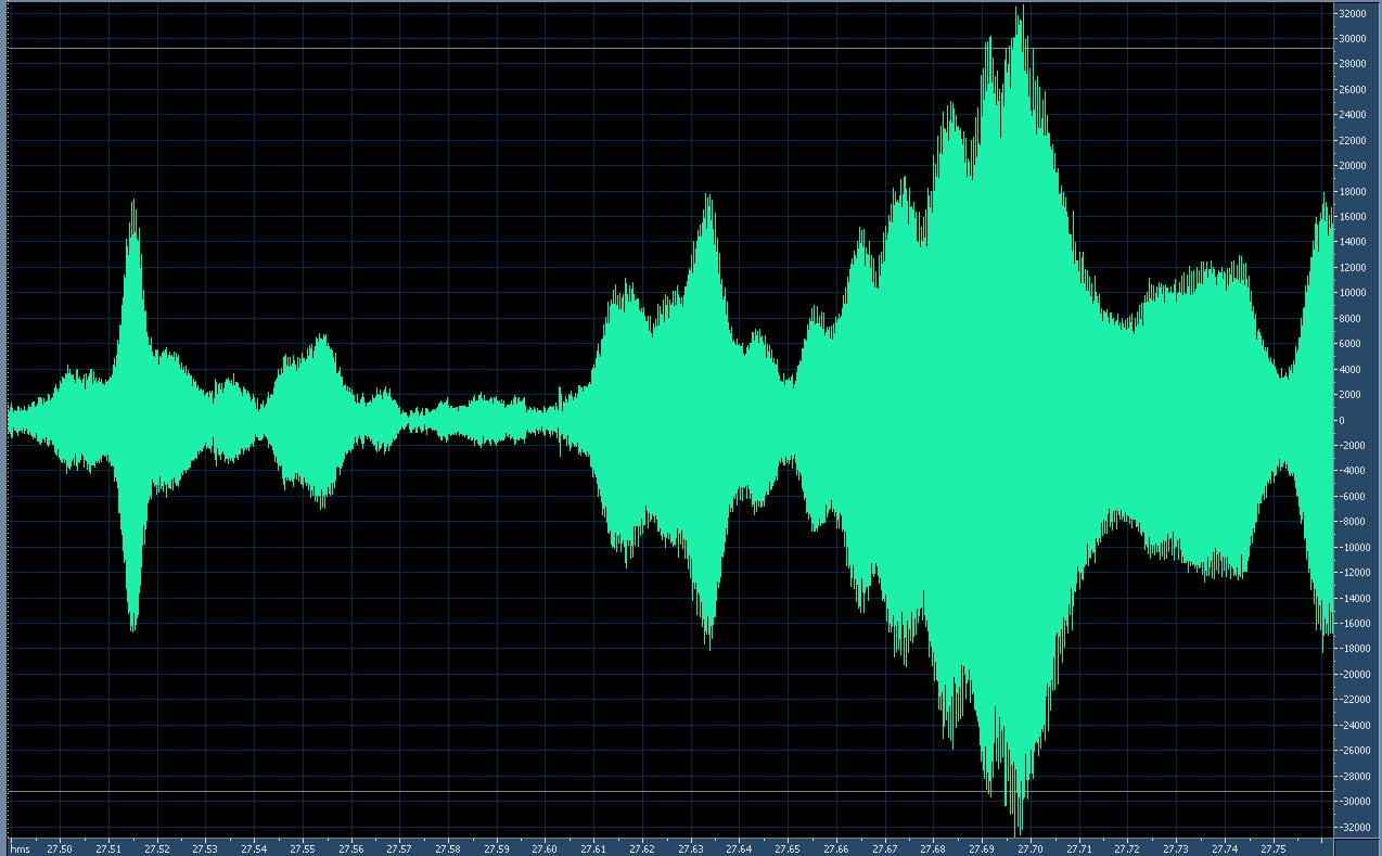 | ||
| Figure 4: Scintillation of the laser-transmitted audio (4 kHz tone). The time span of this particular graph is just over 250 milliseconds (1/4 second) Click on the image for a larger version. |
 |
| Figure 5: Scintillation on the LED-transmitted audio (4 kHz tone). In contrast to the image in Figure 4, the time span of this amplitude representation is nearly 10 times greater - that is, approximately 2 seconds. The rate and amplitude of the scintillation-caused fading are dramatically reduced. Click on the image for a larger version. |
Laser scintillation:
As can be seen from Figure 4 there is significant scintillation that occurs at a very rapid rate. The reference of this image is, like the others, based on a full-scale 16 bit sample. Analysis of the original audio file reveals several things:
- While the "primary" period of scintillation is approximately 10 milliseconds (100Hz) but there is evidence that there are harmonics of this rate to at least 2.5 milliseconds (400 Hz) - but the limited temporal resolution of the test tone makes it difficult to resolve these faster rates.
- Other strong scintillatory periods evident in the audio sample occur at approximate subharmonics of the "primary" scintillatory rate, such as 75 and 150 milliseconds.
- The rate-of-change of amplitude during the scintillation is quite rapid: Amplitude changes of over 30 dB (a factor of 1000) can occur in just 20 milliseconds.
- The overall depth of scintillation was noted to be over 40dB (a factor of 10000) with frequent excursions to this lower amplitude. It was noted that this depth measurement was noise-limited owing to the finite signal-noise ratio of the received signal.
Figure 5 shows a typical example of scintillation from the LED using the same size emitter aperture as the laser. Analysis of the original audio file shows several things:
- The 10 millisecond "primary" scintillatory period observed
in the
Laser signal is pretty much nonexistent while the 20
millisecond
subharmonic is just noticeable.
- 150 and 300 millisecond periods seems to be dominant, with strong evidence of other periods in the 500 and 1000 millisecond range.
- The rate-of-change of amplitude is far slower: Changes of more than 10 dB (a factor of 10) did not usually occur over a shorter period than about 60 milliseconds.
- The overall depth of scintillation was noted to be about 25 dB (a factor of about 300) peak, but was more typically in the 15-18dB (a factor of 32-63) area.
A "Scintillation Compensator":
Despite the redundant nature of the speech maintaining reasonable intelligibility, it became quite "fatiguing" to listen to audio distorted in this manner so another device was wielded as part of an experiment: The "Scintillation Compensator", the block diagram being depicted in Figure 6, below.
 |
| Figure 6: Block diagram of the "Scintillation Compensator" system. Click on the image for a larger version. |
Figure 7:
Audio clip with a"Before" and "After" demonstration
of the "Scintillation Compensator"
Music: "Children" by Robert Miles, used
in accordance with U.S. Fair Use laws.
Music: "Children" by Robert Miles, used
in accordance with U.S. Fair Use laws.
One of the more striking differences is that in the "before" portion, the background hum from city lights remained constant while in the "after" portion it varied tremendously, more clearly demonstrating the degree of the amplitude variation being experienced. What is also interesting is that the latter portion of the clip is much "easier" (e.g. less fatiguing) to listen to: Even though syllables are lost in the noise, being obliterated by hum rather than silence in the first part of the above clip, the fact that there is something present during those brief interruptions, even though it is hum, seems to appease the brain slightly and maintain "auditory continuity".
It should be pointed out that the "Scintillation Compensator" cannot possibly recover the portions of the signals that are too weak (e.g. lost in the thermal noise and/or interference from urban lighting) but only that it maintains the recovered signal at a constant amplitude. In the first portion of the clip in Figure 7 it was the desired signal level that changed while in the second portion it was the background noise that changed. In other words, in both examples given in Figure 7, the instantaneous signal-to-noise ratio was the same in each case.
Practical uses for all of this stuff:
The most important point of this exercise was to demonstrate that a larger aperture reduces scintillation - although that point might be a bit obscured in the above discussion. What was arguably more dramatic - and also important - was that the noncoherent light source seemed to be less susceptible to the vagaries of atmospheric disturbance. This observation bears out similar testing done over the past several decades by many others, including Bell Labs and the works of Dr. Olga Korotkova.
For a brief bibliography and a more in-depth explanation of these effects visit the page "Modulated Light DX" - LINK - particularly the portion near the end of that page.
The reduction of scintillation has interesting implications when it comes to the ability to convey high-speed digital information across large distances using free-space optical means under typical atmospheric conditions. Clearly, one of the more important requirements is that the signal level be maintained such that it is possible to recover information: Too low a signal, it will literally be "lost in the noise" and be unrecoverable.
As the demonstrations above indicate, the "average" level may be adequate to maintain some degree of communications, but the rapid and brief decreases in absolute amplitude would punch "holes" in data being conveyed, regardless of the means of generating or detecting the light. Combating this would imply the liberal use of techniques such as Forward Error Correction (FEC) and interleaving of data over time - not to mention some interactive means by which "fills" for the re-sending of missing data could be automatically requested. The "'analog' analog" to these techniques is the aforementioned ability of the human brain to "fill in" and infer the missing bits of information.
While lasers are well-known to be "modulatable" at high rates, doing so for LEDs is a bit more problematic due to the much larger device (die) sizes and commensurate increase in device capacitance. To rapidly modulate an LED at an ever-higher frequency would also imply an increase of "dV/dT" (e.g. rate of voltage change over time) which, given the capacitance of a particular device would also imply higher instantaneous currents within it, effectively reducing the average current that could be safely applied to it. What this means is that it is likely that specialized configurations would required (e.g. drivers with fast rise-times at high current; structurally-small, high current/optical density LEDs etc.) to permit direct modulation of very high (10's of megabits) data rates.
Using the aforementioned techniques has rather limited utility when the free-space optical links extend out to many 10's of miles/kilometers owing largely to the vagaries of the atmosphere and the practical limits of optical flux with respect to "link margin" (e.g. the need to use safe and sane amounts of optical power to achieve adequate signal to recover information - particularly as the rate of transmission is increased) but it may be useful for experimentation.
Additional information on (more or less) related topics:
Using the aforementioned techniques has rather limited utility when the free-space optical links extend out to many 10's of miles/kilometers owing largely to the vagaries of the atmosphere and the practical limits of optical flux with respect to "link margin" (e.g. the need to use safe and sane amounts of optical power to achieve adequate signal to recover information - particularly as the rate of transmission is increased) but it may be useful for experimentation.
Additional information on (more or less) related topics:
- Throwing One's Voice 95 miles on a lightbeam - link - Details of experiments with high-power LEDs over a 95 mile (152km) optical path
- Voice on a Laser Beam - link - General information about using PWM techniques for Laser diode (and LED) modulation
- Gate Current in a JFET - link - The development of a highly-sensitive optical receiver that utilizes JFET gate current.
- The "Modulatedlight.org" web pages - link - This collection of web pages offers a large resource for many things related to free-space optical communications, including experiments, equipment and links to other related sites.
- For more information about the "Scintillation Compensator" and the "Audible S-Meter" used to set up the optical links, look at the page "An Audio Interface Device for Speech Bandwidth Optical Communications" - link
[End]


