 |
| Figure 1: The TS-590G into which the ProgRock was installed. |
One option for addressing this issue is the use of the QRP Labs ProgRock 2 - LINK. This unit is relatively inexpensive (US$18 at the time of writing) and has a stability of 0.25ppm - which is likely better than the original TCXO offered by the manufacturer - and likely less expensive as well.
This page describes not only the installation of the ProgRock 2 in a Kenwood TS-590, but also in the TS-570: These two radios use very different frequencies, but the ProgRock 2 is easily programmed to whatever is needed!
Any weird frequency
Square waves are OK The ProgRock 2 produces a square wave output, rich in (odd-order) harmonics - but is this OK for use in a radio? It should come as no surprise that modern radios use the reference oscillator - the function being provided by a TCXO - as the basis for timing (possibly) every other frequency-determining module - and this is done digitally. Somewhere along the line, the signal being output by the reference oscillator - whether it's a TCXO, an ordinary crystal oscillator or even the ProgRock - will be converted to a digital signal, anyway. In many cases, the TCXO - if not the original oscillator - already produces a square wave which means that the rest of the circuitry is, by default, happy with the square wave output from the ProgRock 2. While not directly applicable here, if a square wave were fed to circuitry via, say, a long, poorly-terminated coaxial cable, the square wave might get badly distorted and the circuitry in the radio may not be able to properly trigger on it - but since the ProgRock's output is being fed directly into the radios circuitry, this is not going to be a problem. |
While it would be convenient if radios had a nice, easy frequency like 10 MHz as their main oscillator, that is rarely the case - and this was true for a friend's TS-590G which wanted 15.6 MHz. This radio, which he purchased second-hand, did not come with a TCXO and based on his experience during June Field Day and winter Field Day (in January) it drifted excessively - more than a few 10s of Hz on 10 meters - enough that he would occasionally get complaints about him being "off frequency" - even if it was he that was calling CQ!
Although an aftermarket unit was available, he was intrigued by the idea of using the ProgRock 2 as this same device could be programmed for any frequency between about 3.5 kHz and somewhere near 300 MHz with a resolution of 1 Hz. Additionally, the ProgRock 2 allows the use of a 1 PPS (1 pulse-per-second) output from a GPS module to "discipline" the oscillator with even greater stability - but more on this later.
Prepping the ProgRock 2
Using the ProgRock 2 is pretty easy: It has a micro-USB connector onboard and when plugged into a computer, it can appear as a serial port - refer to the manual for the appropriate driver. Using a serial terminal program - like PUTTY - one simply enters the frequency, to the nearest 1 Hz, hit the "S" key to save it to memory and you are pretty much done. The ProgRock will allow the output of more than one frequency if needed (the manual has more detail) but we will be using output #1, which is also the one into which we'd program the needed frequency, setting the others to zero (e.g. "off").
 |
| Figure 2: ProgRock 2 with the 3.9 and 10k resistors mounted to allow the external application of a 1pps signal from a GPS module to stabilize the frequency further. The bottom side of the ProgRock 2 is shown. Click on the image for a larger version. |
Having said that, there's a bit more to it in that it needs power, ground, and the signal output needs to get into the radio - but more on that in a moment.
As my friend wished to experiment with using a 1 PPS source to nail it down to frequency, a 3.9k series resistor was added to the "1pps" pin along with a 10k resistor to ground to keep the pin from "floating" around in voltage when nothing was connected to it. Figure 2 shows these resistors mounted on the "bottom" side of the board: The upper resistor is the 3.9k connected to the 1pps pad with the lower, 10k resistor connected to a ground pad. The junction of the two (with the yellow piece of insulating tubing) is where the 1pps input would be connected.
The use of the 3.9k resistor is described in the ProgRock 2's documentation which notes that the onboard microcontroller operates from 3.3 volts - but placing this resistor in series (the value of which isn't particularly critical) limits the current into the logic pin, allowing it to be safely driven by a 5 volt - or even 12 volt - 1pps pulse.
 |
| Figure 3: The Progrock 2 mounted to the original TS-590 TCXO board using short, insulated jumper wires. The top side of the ProgRock 2 is shown. Click on the image for a larger version. |
There's a place for it!
While the "stock" TS-590 did not come with a TCXO, there was a small "daughter" board adjacent to the portion of the circuit board with the stock oscillator on which the user is expected to solder a TCXO in the form of a "crystal can" oscillator module - or, in the case of some after-market units - replace that board entirely. As the ProgRock 2 is roughly the size of a postage stamp (it will fit within an HC-6 crystal can!) it could be wedged on this same board - which is convenient as this board also carries 5 volt power for the original TCXO, so a bit of pretty easy "micro" surgery was undertaken.
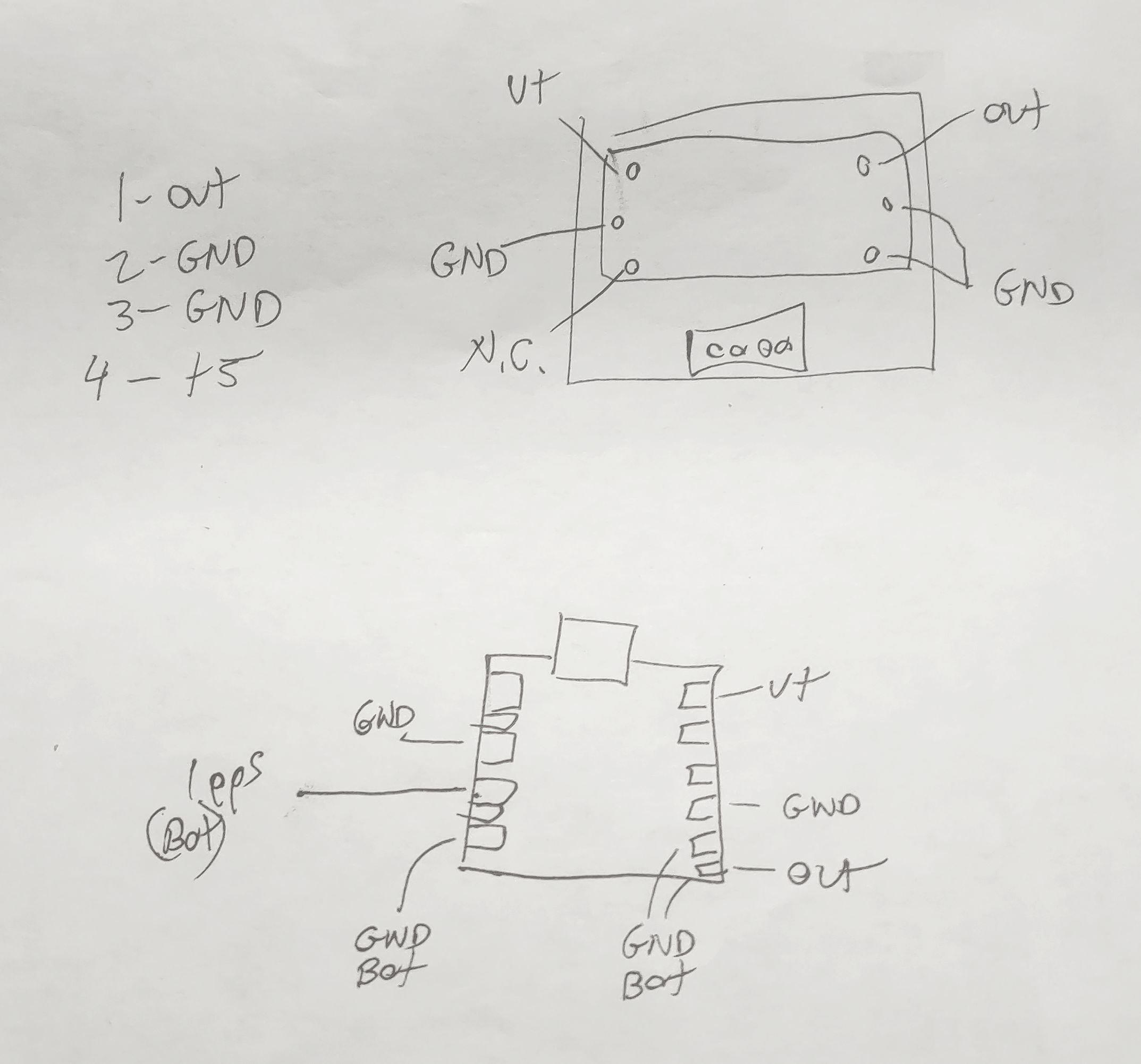 |
| Figure 4: A hand-drawn diagram showing the connections on the top side of the TS-590's TCXO board and the ProgRock 2 board. Click on the image for a larger version. |
Figure 3 shows how the ProgRock 2 board was mounted on the original TCXO board. Fortunately, all of the needed connections are there: +5 volts to run the original TCXO, ground, and the signal output. Figure 4 shows a hand-drawn diagram showing the original TCXO board (top) with its pin locations while a representation of the ProgRock board (with the USB connector oriented on top) is in the lower drawing along with its connections.
Using small gauge, insulated wire liberated from a scrap of CAT5 Ethernet cable, short-as-possible jumpers were run between the TCXO board and the ProgRock. In Figure 3, the "ground" connections were made using green wire - one of them utilizing the body of the USB connector - while the output signal used blue and the power used orange: In the upper-right corner of the ProgRock 2 board - just above the USB connector - you can just see the yellow insulating tubing of the 1pps connection.
There is JUST enough room - if one scrunches the edge of the ProgRock 2 board against the TCXO board's white connector (and by routing wires such that they are not between the ProgRock 2 board and the connector) so that it will fit in the original location within the TS-590 as can be seen in Figure 5, below.
Comment:
It was noted - during testing of the TS-590 - that the combination of 10 meters at 100 watts while using the built-in tuner - seemed to "glitch" the ProgRock for reasons unknown, although it's suspected that magnetic fields from the PA/Tuner board are finding their way through the aluminum chassis from the opposite side. Simply tipping the ProgRock 2 board from being flat against the original TCXO board to more of an angle and adding another ground wire jumper to the TCXO board seemed to fix this.
One important consideration is that you MUST be sure that there's a blocking capacitor somewhere between the output of the ProgRock 2 and the input of the circuit that it's driving. As it turns out, the stock TS-590 TCXO board has such a blocking capacitor - but if your application does not, or you are not sure if it does, simply use a 0.001 to 0.1uF capacitor in series with the output - and this capacitor may also serve in lieu of a jumper wire in connecting it to the radio.
Finally, don't forget to disable the original oscillator of the radio into which you are installing the ProgRock 2. In the case of the TS-590, there are two jumpers that must be removed - one to cut power to the original oscillator and the other to disconnect its output - these black jumpers are just visible to the right of the orange connector on the jumper cable to the TCXO board on Figure 5. In some radios the TXCO replaces the original oscillator entirely so there's no need to "disable" it.
 |
| Figure 5: The TCXO + Progrock 2 boards, installed in the TS-590. There is enough wire length to connect the USB to program the ProgRock in-situ if the mounting screw is removed. Click on the image for a larger version. |
Checking the calibration
You might notice that the TS-590's TCXO board is connected with a short, 4-wire jumper (the red, black and green wires in Figure 5) and this is long enough to allow connection of the ProgRock 2 board to a USB cable and a computer to allow the frequency to be adjusted "live", while the radio is in operation - this requires removing the single mounting screw to permit the board to "hang loose".
Simply setting the ProgRock 2 to 15.6 MHz exactly in the configuration menu resulted in the TS-590 being within 2 Hz of the correct frequency when checked against the 10 MHz WWV/H signal - this difference likely because the ProgRock 2's onboard 25 MHz oscillator was very slightly off, but well within the 0.25ppm tolerance.
But what if you wanted it to be closer? Keep in mind that the frequency tolerance of the ProgRock 2's own TCXO is 0.25ppm which amounts to as much as 2.5 Hz at 10 MHz (or 7.5 Hz at 30 MHz) so absolute accuracy over a wide temperature range is unrealistic - but "dialing it in" at the typical room temperature (or that of the radio's interior after it has been on for a while) is quite reasonable - although there's a caveat to this if you plan to use the 1pps input as we'll soon discuss.
Dialing it in
If you have an ultra-precise frequency reference such as a GPS-disciplined oscillator or a Rubidium reference, by all means use it - but if you don't, you can use an off-air frequency reference like WWV, WWVH, CHU, BPM, or whatever else is near you that is KNOWN to be very precise - but the higher the frequency, the better.
Using 15 MHz WWV as an example, tune the radio USING THE KEYPAD so that it is exactly on frequency: Note that the TS-590 can tune smaller than the 10 Hz steps shown on the display, so turning the dial doesn't guarantee that you are on the "zero Hz" frequency step. Without bumping the main tuning knob and knocking it off by less than a 10 Hz step listen for the WWV transmission to hear the portion when they are transmitting the 500 or 600 Hz tone (this step won't work if they are not transmitting this tone) and switch between USB and LSB: If you hear any difference in tone, you may wish to tweak the ProgRock's frequency up or down as appropriate. If the tone on USB is slightly lower than that on LSB, the ProgRock's frequency needs to be set slightly lower.
An alternative method to setting the frequency is to use a spectrum analysis program - "Spectran" by I2PHD (LINK) is probably the easiest to use. In this case, one would tune Spectran for a 1 kHz tone and configure it to pick up the audio via the computer's microphone or a web cam - or using a direct audio connection such as a rig interface or audio cable from the radio. If you are using WWV/H for this, it's suggested that you first listen using AM and verify that your sound card's sample rate is accurate, with Spectran showing precisely 500 or 600 Hz during the periods when WWV/H is transmitting those tones. If you find that it's not showing exactly 500 or 600 Hz (to within a Hz or so) you may wish to try a different sound card/computer combination or just do a bit of math to compensate for the slight difference in the audio card's sample rate.
Using USB on the TS-590, tune exactly 1 kHz below WWV/H (e.g. 14.999 kHz) using the keypad and measure the frequency of the carrier: If the tone frequency measures slightly high when using USB, the ProgRock's 15.6 MHz frequency can be increased slightly - but remember that it may be done only in 1 Hz steps. Remember that 1 Hz at 15.6 MHz will cause a frequency shift of about 0.6 Hz at 10 MHz and almost 2 Hz at 30 MHz as the effect will be proportional to the radio of the reference frequency (15.6 MHz in this case) and the frequency to which the receiver is tuned.
Note: If you have a known-accurate reference oscillator of your own (such as a GPS Disciplined oscillator, Rubidium oscillator or similar) by all means, use it!
Comment about tuning step size.
Many modern transceivers tune in 10 Hz steps or finer - but note that these steps are often not exactly what they may seem. For example, some radios' 10 Hz steps aren't exactly 10 Hz each - some being a bit more, some being a bit less - but that they will average 10 Hz steps. The same goes for the smaller step sizes as well.
Keep this in mind when you are attempting to set/measure a given radio exactly to frequency as this slight difference in step size may result in some frequencies being slightly different from what is expected and this difference may vary by seemingly random amounts.
Using the (optional) 1pps input on the ProgRock 2
As noted earlier, the ProgRock 2 can take a 1pps input from a GPS receiver module, using this to make gradual corrections of the frequency. Doing this if the GPS signal is reliable will result in the frequency being very stable over a wide temperature range, but there are two caveats to this:
- The ProgRock 2 doesn't (yet?) have in its firmware a means by which one can input an offset of its 25 MHz TCXO frequency. As the onboard 25 MHz TCXO is not likely to be exactly correct, this means that if you set set the frequency at room temperature - and the oscillator is slightly off - when you apply a 1pps input the frequency will then be shifted assuming a 25 MHz clock frequency. The reason for this is that the 1pps will set the frequency as if the onboard 25 MHz TCXO were 25 MHz, exactly - but since it probably isn't (remember - it's rated to be within 0.25ppm) a frequency shift will result.
- In other words, if you want your radio to be precisely on frequency with a 1pps input, you will have to "dial it in" with 1pps applied and expect it to be slightly off when no 1pps signal is present.
- If you ever do apply a 1pps signal - even briefly - the Progrock 2 will "remember" that offset even when the 1pps is removed until the unit is power-cycled. If the 1pps is removed, the oscillator will now be free to drift with temperature.
- The frequency step corrections as a result of the 1pps input are not infinitesimally small. What this means is that with 1pps applied, every second the frequency will shift slightly, typically hovering above and below the target - but the magnitude of these corrections may be set in the configuration of the ProgRock 2.
- For most modes on HF - including FT8, FT4, PSK31, CW, Sideband or even many digital modes - these small "sub-Hz" shifts would likely be inconsequential.
- If you are using a digital mode where fractional-Hertz frequency shifts are important, you may want to carefully consider using 1pps at all, weighing the pros and cons of having seemingly random small frequency shifts. Modes where this may be important would be WSPR, FST4W (particularly the modes longer than 2 minutes), coherent CW, during an FMT (Frequency Measurement Test) or any other instance where small frequency steps may be disruptive.
- If you are in a situation where the continual frequency correction is an issue but you want the frequency to be closer than what the TCXO onboard the ProgRock will allow you might consider manually applying the 1pps signal intermittently to occasionally recalibrate the frequency. This would allow the frequency to drift slightly with temperature between calibration intervals.
- While one may configure the adjustment size in the ProgRock 2 and likely minimize the size of the frequency adjustment steps, remember that it must be capable of correcting for the normal and expected frequency changes related to temperature. This need sets a minimum correction size that will be practical and the varying environments with differing temperature and its stability will affect this.
- If you are using a 1pps input on a radio that operates in the VHF/UHF and/or microwave frequencies, these small frequency shifts will be proportionally larger and may even be noticeable on SSB and/or as slight "clicks"in received audio - possibly making the radio unusable for digital modes altogether. It may be possible to configure the ProgRock 2 to mitigate this somewhat by reducing the magnitude of the corrections, but they will always be there.
* * *
A ProgRock 2 in the Kenwood TS-570
The (older) Kenwood TS-570 (all variants) can also be retrofitted with a ProgRock 2 in lieu of the Kenwood "SO-2" TCXO - and it's also pretty easy. Using the same steps as above, program the ProgRock 2's "Clock 0" for 20000000 Hz (20 MHz exactly). I modified my own TS-570 for the same reason that my friend modified his TS-590: The original oscillator would audibly drift in frequency with temperature and it was over 100 Hz high on 10 meters (approx. 25 Hz on 40 meters) once it warmed up, causing the occasional complaint that I was off-frequency. I do not use this radio for digital modes like FT-8, but if I had, I'm sure that I would have made this modification some time ago!
 |
| Figure 6: The ProgRock 2 installed in place of the original Kenwood SO-2 TCXO in the TS-570. The wires through the board were bent and soldered to the V+ and three ground pins. The output of the ProgRock 2 is connected to the "out" pin on the board via a 47 ohm and 1000pF capacitor in series. Click on the image for a larger version. |
Rather than solder in the TCXO, cut five short pieces of tinned wire (20-24AWG, 0.6-0.8mm dia) to be about 3/4" (20mm) long and solder them in the five holes into which the original TCXO was soldered and re-install the board.
On the board itself you'll notice that two of the holes are marked - one for power and one for the "out" pin of the TCXO into which we will feed our 20 MHz clock from the ProgRock 2: The other three pins are ground. First, the ProgRock 2 is "dry fit": It is placed on the circuit board (with a piece of foam or cardboard underneath to space it slightly away - perhaps 1/8" to 3/16" or 3-5mm) and the wires that we soldered bent around to the contact pads and trimmed, taking care that they not touch the pads on the back side of the board or anywhere else that they shouldn't.
As can be seen in Figure 6, the "V+" pin was wrapped around and soldered to the "V+ pin (which carries 5 volts) on the ProgRock 2 (the one in the lower-right corner of the ProgRock board in Figure 6) while two of the the three wires for the ground connect to top-side "GND" pads on the ProgRock while the third is soldered to the top of the USB connector. As the ProgRock 2 is very light, these wires are more than adequate to hold it into place - just be sure to keep the board height low enough to avoid interfering with the shield when it is replaced.
The top-right corner pad on the ProgRock 2 in Figure 6 is the "CLK 0" that we programmed - but like the TS-590, it must be capacitively coupled to the clock input on the TS-570 and this is done with a series capacitor: I used a 1000pF capacitor for this, but anything between 470pF and 0.1uF would be fine for this radio. On the schematic I noted that there is a 10pF capacitor to ground in the TS-570 on the "out" pin so I also included a 47 ohm resistor in series with the capacitor just in case the output of the synthesizer would be "unhappy" with capacitive loading - and also to reduce the amount of RF drive into the '570's clock input. This resistor may not have been necessary, but hey, it's just a resistor so why not play it safe? The final steps are to cut the two resistors, R503 and R504, seen to the right of the ProgRock 2 board: This necessary step disconnects the power and the output lead of the original oscillator circuit.
Upon reassembling the TS-570, I tuned in WWV on 5 MHz and switched between LSB and USB (with the RIT set to zero) and heard no discernible change in pitch during a part of the transmission with the tone indicating that the radio was "dead on" frequency. As the ProgRock 2 is rated for 0.25ppm stability, it should stay within 5-8 Hz on 10 meters, worst-case - about 1/20th as much drift as with the original oscillator!
While I could have done so, I chose not to add the resistors to permit the external application of a GPS-based "1pps" input to "lock" the ProgRock 2, as was described above for the TS-590.
From start to finish, it took me about an hour to program and install the ProgRock 2 in my TS-570 - but your mileage may vary.
* * *
A ProgRock 2 in the Kenwood TS-480
 |
| Figure 7: The "option" board in the TS-480. |
Looking carefully, you'll see electrolytic capacitor C973 and to the left of it, there's a mounting screw: Both of these interfere with the mounting of the ProgRock 2. Fortunately, this "sub-board" is easily removed with the removal of the three screws and "un-clipping" it from the white connectors which allows C973 - which is used for filtering the DC power to the TCXO - to be removed: As the TCXO itself has its own power supply filtering, this capacitor is unnecessary. With the board removed, mounting the ProgRock 2 is also made much easier.
 |
| Figure 8: The ProgRock 2 in the TS-480 |
The "downside" of this is that the TCXO blocks access to one of the screws. While we could have installed "flying leads" on the board which allowed the ProgRock 2 to be moved around a bit to get access to the screw, we chose to leave out this mounting screw - but it was glued to the PC board just in case we changed out mind. The other downside is that if we wanted to install Option Filter 1, we would have to re-think the mechanical installation of the ProgRock 2 - perhaps tilt it at an angle. Of course, if one wished to have just one optional filter, it can be installed in the "Option Filter 2" position, instead.
* * *
Using the ProgRock2 in other radios
As the ProgRock2 can be programmed for about any frequency you like, it can be used in radios other than the Kenwood TS-590, TS-480 or TS-570. The ProgRock 2 draws a modest amount of current (40-60mA) so its addition will likely not be consequential in power consumption on "desktop" and "mobile" radios - but it may be significant on a QRP or portable radio. It's likely that most radios do NOT have a handy board onto which the ProgRock 2 may be easily mounted like the TS-590, but the unit is small enough that it will likely fit in/near the location intended for the oscillator/TCXO.
Be sure to use as short as leads as practical and it will likely be necessary to use some sort of adhesive (foam pad or glue) or some sort of "zip tie" to hold the ProgRock 2 board into place. If possible, be sure to install it such that the ProgRock 2 may be moved so that its USB port may be connected to a computer to allow final tweaking of frequency once it is installed - at least before it is secured into place: Once the frequency has been "dialed in" it's unlikely that you'll need to readjust it any time soon.
The ProgRock 2 is also rather flexible in its power supply, but even though it is rated to 12.0 volts, I would NOT recommend allowing more than 10 volts ever be applied to it - and the input voltage can be as low as around 4 volts meaning that it's likely that if the radio itself has an already-existing supply rail (5 volts like the TS-590 - many radios have an 8, 9 or 10 volt supply as well) that will work nicely or one could use an appropriately-chosen series resistor (likely in the 47-82 ohm range for a 12 volt supply - but please do your own measurements) to drop its supply by a few volts.
As noted above, you must be sure to keep the DC on the output terminal of the ProgRock from being shorted to ground (via a transformer or inductor to ground) or to another voltage source (such as a bias network of an amplifier/buffer) as it has no blocking capacitor of its own. In the TS-590 the original TCXO board had its own blocking capacitor - but if your intended circuit doesn't have such - or if you don't know if it has one - simply add a 0.001 to 0.1uf (value not critical) series blocking capacitor of your own.
Most "recent" radios (e.g. those made since the early-mid 90s) have a single frequency reference for their synthesizer - but ones prior to this (and a few after) may have more than one master oscillator that determines the precise frequency. It's worth noting that the ProgRock 2 can output more than one frequency at a time (three if you are not using the 1pps input - just two if you are) and it may be possible to program one of the ProgRock's other outputs to another useful frequency. One possibility is for very old analog radios that sport a 100 kHz crystal calibrator or similar: The ProgRock 2 would be excellent for this purpose.
In some cases, these "other" frequencies may include the radio's BFO (Beat Frequency Oscillator) or HFO (Heterodyne Frequency Oscillator) in which case you may need to be more creative - but it's worth noting that the ProgRock has up three "digital" inputs that may optionally be used allowing up to eight separate frequency combinations to be produced - possibly allowing one to replace impossible-to-find crystals in vintage radios - but this is a possible topic of another article.
* * * * *
This post stolen from ka7oei.blogspot.com
[END]


