In the June 18, 2018 entry of this blog (see that page here) I described a device that reduced the lower-frequency (below approximately 10 MHz) by approximately 12dB while leaving higher-frequency signals (pretty much) untouched.
Note: On 26 September, 2020, I brought up this topic yet again - see "Revisiting the limited attenuation High Pass Filter - again".
Since the original posting of this blog entry I was made aware of an 1977 article on this very topic - you can read it HERE. (The article in question begins on page 3 of the PDF.)
Why the need?
The discussion below applies equally to any SDR-type receiver that is connected to an HF antenna. Some of these receivers have built-in band-pass filtering, but some of these - particularly the RTL-SDR types - may not: These SDRs, since they are of limited coverage, are better-served with specific "window" type band-pass filters for the frequencies of interest, but the discussion below may still apply.
As it turns out, the KiwiSDR is "sort of" deaf. Using a variety of measurement techniques, the absolute sensitivity of the KiwiSDR sitting on my workbench at 28.25 MHz was determined to be approximately -155dBm for a 0 dB signal-noise ratio in a 1 Hz bandwidth.
While this may sound impressive, it isn't quite enough to allow the receiver to "hear" the theoretical noise floor of -160dBm (1 Hz bandwidth) at 30 MHz according to ITU-R P.372.7 as depicted in the chart below in Figure 1:
 | |
| Figure 1: "Typical" noise floor for various radio environments. Because the above chart is based on a 500 Hz bandwidth, one would subtract 27dB from the power level to scale to a 1 Hz bandwidth. |
The obvious answer is to add an amplifier: Assuming no other losses, about 10dB is more than enough to overcome the KiwiSDR's noise floor - plus "a bit extra" to minimize the dilution by the receiver's noise.
There is a problem with doing this is hinted at the nature of the graph itself. As one can see, the noise at 5 MHz is nearly 20dB higher than that at 30 MHz. While this means that the intrinsic sensitivity of the receiver is more than adequate at these (lower) frequencies, there's another problem: Signals at these lower HF frequencies will also be very much stronger.
It was observed that the KiwiSDR would exhibit an A/D converter overload (at 28.25 MHz) at -15dBm - and while this is a much higher level than the signal levels depicted in the chart above - because Figure 1 just depicts the noise level - the fact that the receiver itself is inherently broadband, much more noise is intercepted. For example, if we were to re-scale the above power levels for a 5 MHz bandwidth, the noise power alone would be increased by 40-ish dB.
This does not take into account that the frequency range below 10 MHz is replete with strong signals in most parts of the world - particularly at night, some of which have been measured to be stronger than -30dBm - and there are multiple signals of this sort that are present, the total power of which can be cumulative. What make things worse is that on these frequencies there are very often strong static crashes - particularly in the summer - that may be equal or stronger than the signals present in their "S-meter" reading, but these crashes are inherently broadband, which means that the receiver is intercepting much more signal than the signal meter will indicate.
The "solution" to this is to put the (overall) signal gain where it is needed: Amplify the high-frequency (e.g. above approximately 10 MHz) signals more than the low-frequency signals - and one way to do this is to construct a filter that attenuates the lower-frequency signals without bothering the higher-frequency signals.
But the previous filter already does this!
The original filter that does this has been in service for months, now - and it has been working very well, but when I installed it, I overlooked something: The gain of the antenna being used drops off precipitously at MF and LF frequencies. What this meant was that with the 12 dB or so drop in signal level by the time one gets to 7-8 MHz persisting down to DC, the signals on the 630 meter amateur band (and lower, for that matter) are also attenuated by the same 12dB - but these same signals - from the antenna - are already dropping off, potentially putting these lower-frequency signals (again) below the KiwiSDR's noise floor.
Reworking the filter:
To that end, I re-worked the filter. Previously, it was simply a 3rd-order high-pass filter with some "bypass" so that a limited amount of the lower-frequency energy would be allowed through and this meant that from the cut-off frequency down to (essentially) DC, there would be 12-ish dB loss. What I needed, instead, was to affect the lower HF frequencies, but leave the very low frequencies alone.
There was a complication: The signal path for the KiwiSDR already includes an effective filter for the AM broadcast ("mediumwave") frequencies (described in the 15 February, 2018 blog entry - "Managing HF signal dynamics and preventing overload with the RTL (and KiwiSDR) receivers" - see that page here) and to have both sets of filtering in series - as it is now - would mean that the KiwiSDR would have difficulty hearing weaker signals on the broadcast band - as it does now. This meant that I needed to reject frequencies between approximately 1.7 MHz to 10 MHz, but leave the signals outside that range alone.
For this, the free "ELSIE" program came to the rescue: A 3rd-order Butterworth filter, centered on 4.2 MHz with a 10 MHz band-pass was determined to provide the necessary rejection at the boundaries and like the previous filter, it, too, would have a controlled amount of bypass to allow some signal to pass through it as the diagram in Figure 2, below, shows:
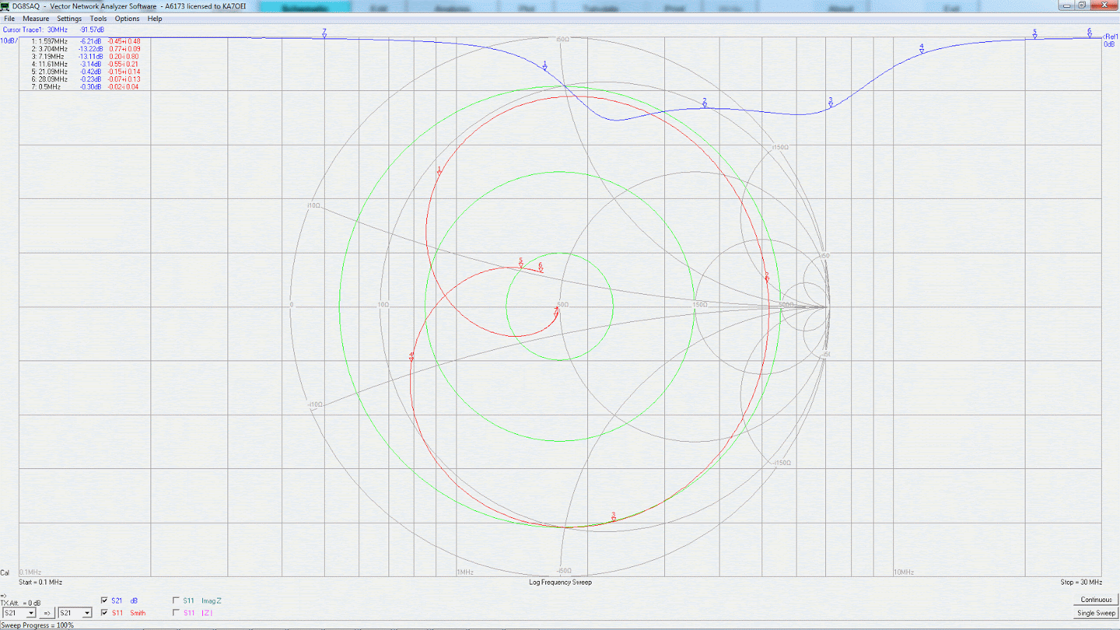 |
| Figure 2: The response plot of the limited-attenuation band-stop filter. Its effect is limited from the top end of the AM broadcast band and down, having at least 10dB of attenuation from about 1.8 MHz and 8 MHz with 13-15dB being more typical between these frequencies. Click on the image for a larger version |
The schematic of this device of may be seen here:
 |
| Figure 3: Diagram of the limited-attenuation band-stop filter. Click on the image for a slightly larger version. |
If you have visited the 15 February, 2018 page, you will notice very distinct similarities between its main filter element and this circuit, right down to the application of signal "bypass" to set a maximum amount of attenuation that can occur.
In this filter, L1/C1, L2/C2 and L3/C3 are resonated to 3.7 MHz with the values selected to provide the desired attenuation at the frequencies at which the cut-off is to begin. In this case, this filter is a slightly-tweaked version of a 3-pole Butterworth filter designed for a 50 ohm termination and has a theoretical 3dB passband of 11 MHz centered at 3.7 MHz. The theoretical -6dB points of basic filter - ignoring R1/R2/L4 - is approximately 1.6 and 8.5 MHz with the -1dB points occurring at around 1.1 and 11.8 MHz.
Components R1/R2/L4 provide a degree of "bypassing" that leaks a controlled amount of signal around this filter: Without these components, the attenuation could be in excess of 60dB near 3.7 MHz, but as can be seen, the actual attenuation is around 14dB, +/- 1dB or so. While a simple resistor could have been used to accomplish this, the L4 slightly reduces the attenuation at the high end of the HF spectrum while R2 suppresses some of the asymmetry seen in the bottom of the attenuation curve that is caused by L4.
 |
| Figure 4: As-built limited-attenuation band-stop filter. This circuit - later put in an enclosure - is built "Manhattan" style using a combination of molded and toroidal chokes. The BNC connectors visible were temporary, used only on the workbench for testing and characterization. L1 and L2 are the black devices about the center, L2 is the red toroid in the foreground and L4 is the molded choke located close to the center pin of the right-hand BNC connector. Click on the image for a larger version. |
Comments:
- As can be seen from the Smith chart in Figure 2, this filter provides a 50 ohm match only at frequencies removed from the portion where the attenuation is occurring. For this reason it is recommended that this filter be placed fairly close to the receiver (or splitter, if several receivers are being used) - this, to prevent impedance transformation on the line. Similarly, it is recommended that this filter be preceded one stage of amplification to source the filter with something near-ish 50 ohms.
- If amplification is used for the receiver, it is suggested that the bulk of amplification be placed immediately after this filter: The attenuation at the lower frequencies will reduce the probability of amplifier overloaded by the often-strong signals at these frequencies as well as the summer static. The impact of the filter on the system noise figure at low frequencies is offset by the typically-high noise level while the low loss of the filter at higher frequencies which means that there will be little overall impact at the high end of the HF spectrum.
- In the case of the KiwiSDR system at the Northern Utah WebSDR, the total amount of amplification is about 22 dB in two stages: At least 10dB is required in the overall system just to bring the receiver's noise floor (at 30 MHz) below the "rural quiet" noise floor - and there are likely to be other system losses that require even more amplification. At the Northern Utah WebSDR, there is about 5 dB of loss between the antenna and the first amplifier, and there is an additional 6.5-7dB of loss in a four-way splitter to feed all of the receivers, so the overall 22dB gain in the system is about right.
This page stolen from ka7oei.blogspot.com
[End]