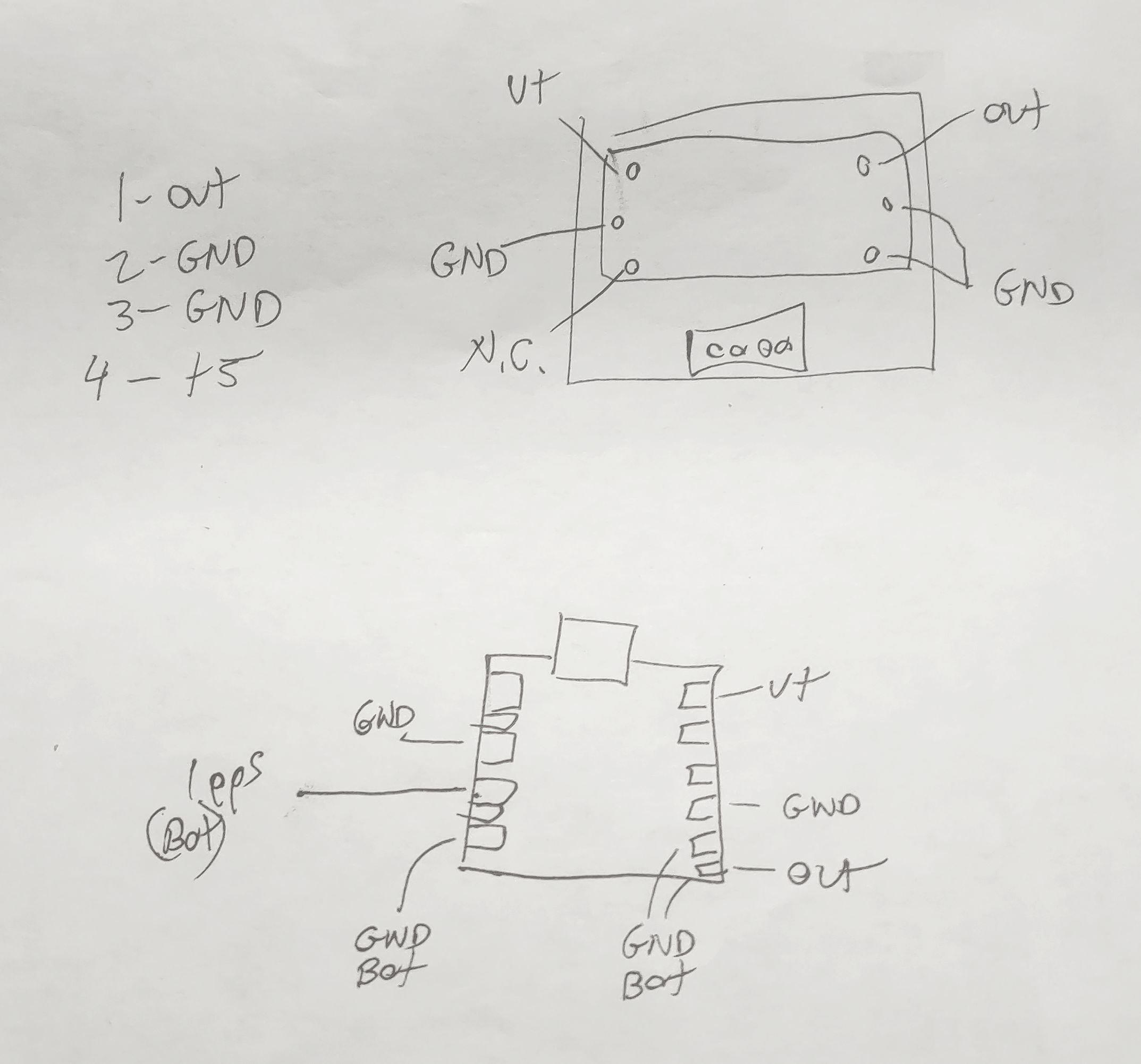
Sunday, June 30, 2024

Reducing QRM (interference) from a Renogy 200 watt (or any other!) portable solar panel system

Figure 1:
Renogy 200 watt folding panel, in the sun
Click on the image for a larger version.
A year or so ago I got a 200 watt foldable solar panel system.  This unit - made by Renogy - consists of two glass panels in metal frames equipped with a sort of "kickstand" assembly to allow it to be angled more favorably with the sun to improve its output.  I use this panel when "car camping" to charge the batteries to run the sorts of things that one might bring:  Lights, refrigerator, amateur radio transceivers and who knows what else.  

On that last point, I've done some "in the field" operating on the HF amateur bands while the battery is being charged and noticed that the charge controller (and not the panel itself!) produced a bit of "hash" on the radio - mostly in the form of frequent "birdies" that swished around in frequency as the solar insolation and temperature varied - as well as a general low-level noise at some frequencies.   

This problem is not specific to the Renogy panel's charge controller, but common to almost any panel+controller combination that you will find.

Nearly all "portable" and RV solar power systems cause QRM:

You will find similar systems built into RVs and campers and these are also well known (notorious, even!) for generating RFI.  The techniques described here to quiet interference from these devices applies equally to those as well - but note that one may have to "scale up" the inductors/capacitors to accommodate higher voltages and currents that may be found in those systems.

By placing the solar panel with charge controller and the battery being charged some distance away from the antenna, this interference could be reduced, but that fact that it was even there in the first place annoyed me, so I did what I have done many times before (see the links to other blog entries at the end of this article) and mitigated it by making fairly easy, reversible modifications to the panel's controller.

Portable solar panels and RFI

In my travels, I've been around other users of portable solar panels of various brands and I have yet to find any commercially-available portable panel+controller combination that does NOT produce noticeable RFI on HF/VHF among the half-dozen or so brands that I have checked. 

In comparison with most of the others that I've been around with radios, the Renogy is comparatively quiet - producing less overall QRM with fairly long wires between the panel/controller and battery - than the others - but I decided that I could make it even quieter!

Where does the QRM come from?

It is NOT the solar panel itself that produces the radio frequency noise, but rather the charge controller attached to it.

Modern charge controllers electronically convert the (usually higher) voltage from the solar panels down to something closer to the battery voltage and this is typically done using PWM (Pulse Width Modulation) which means that these devices contain high-power oscillators:  This is true for simple "PWM" types of charge controllers as well as those using "MPPT" techniques.  It's this oscillation / switching action that produces a myriad of harmonics that can extend through the HF spectrum - and even into VHF/UHF!

The "Antenna" in this case consists of two parts of the PV system as depicted in the drawing below:

Figure 2:
A typical solar charging system showing the separation of the two major components that can radiate interference:  The panel itself, connected to the input of the charge controller and the wires and load connected on the output side.
If there is even a slight amount of differential between the two at radio frequencies, the system will radiate.
Click on the image for a larger version.
 
In other words:
  • The wires connecting to the load.  Typically a battery being charged - which can be connected to other things (e.g. vehicle, inverter, etc.)  The wires connecting the panel to these other things - and those devices themselves - act as part of the "antenna" that potentially radiates noise.
  • The solar panel itself.  The solar panel consists of large plates of metal - not only the silicon of the panel, but any metal frame and wiring:  This large area of conductive material offers a suitably large aperture to permit radiation of HF RF.

The "load" and solar panel constitute two different parts of the charge controller's system when it comes to radiation RF:  The panel is connected to the INPUT of the PWM circuitry while the wiring is connected to the OUTPUT of the PWM circuitry, effectively forming a dipole antenna.  To a degree, the electrical lengths of these two conductors - which can include power cords or even a vehicle - overall can broadly resonate, affecting certain frequency ranges more than others.

The reason for the generation of the interference is due to the fact that the PWM circuitry (which is operating at a frequency of 10s or 100s of kHz) uses square waves, rich in harmonics.  As the voltage input (from the panel) and the output (to the battery/load) are different parts of the PWM circuit, they necessarily have different waveforms on them.

Figure 3:
Charge controller with additional filtering showing added
bifilar-wound chokes on both the input and output leads.
Click on the image for a larger version.

While this device does have some filtering to provide a degree of input impedance reduction (fairly high capacitance) and smoothing of the PWM waveform of the output (more capacitors and likely some inductance) the extent to which this filtering is implemented is suitable for the purpose of providing clean DC power to the load and maximize power conversion efficiency, this filtering - and likely the controller's circuit board itself - was likely not intended to provide the high degree of RF suppression needed to make it quiet enough to avoid the conduction of RF energy onto its conductors which is then picked up by a nearby receiver.

Containing the RF energy
 
As the controller itself is potted with a silicone material, it's not practical to modify it directly to make it RF-quiet - and there is no need to do so:  Instead, we must take steps to eliminate any differential RF currents that may exist between DC Input and DC output terminals.

Ferrite alone is NOT the answer!

One may presume that the answer to this problem is the implementation of RF device such as snap-on or toroidal ferrite devices - and you would be partially correct.  Any practical inductor - such as that formed by the introduction of a ferrite device onto an existing wire - will have rather limited efficacy in quashing RF currents.

Snap-on devices (e.g. those through which a wire passes) have very limited usefulness at HF frequencies (<30 MHz) - especially on the lower bands - as they simply cannot impart a significant amount of reactance in the conductor onto which they are installed.  At higher frequencies (VHF, UHF) they can have a greater effect - but their efficacy will usually be disappointing at HF.

Using a device that can accommodate multiple turns through its center such as a toroid (or even a larger snap-on device) it may be possible to get up to a few hundred ohms of reactance on a conductor across a fairly wide frequency range - but even this will be capable of reducing the amount of RF by 10-20 dB (2-3 "S" units) at most:  Depending on the intensity of the RFI from the solar controller, this may not be enough to quash the interfering energy to inaudibility - particularly in a remote and otherwise "RF Quiet" location.

To be sure, it's worth trying just the ferrite devices by themselves to see if - in your situation - it reduces the RF interference from the controller to your satisfaction, but remember that the location where you are likely to be using this panel is probably far quieter (RF-wise) than your home QTH:  A "quiet" Solar charging system may seem quiet enough at your noisy home QTH, but could still be noisy in the middle of nowhere.

The addition of capacitors to the circuit can improve the efficacy over ferrite alone by orders of magnitude.  Consider the diagram below:

Figure 4:
Diagram, including additional filtering.  L1 and L2 are the bifilar chokes seen in Figure 3, above while the capacitors (C1a, C1b, C1c and C2a, C2b and C2c) and their implementation are described below.
Click on the image for a larger version.
 
Ferrite devices L1 and L2 are comprised of bifilar-wound inductors on the DC input/output lines, respectively.  These inductors will suppress common-mode RF energy that may appear - but these alone are not likely to be quite enough.
 
In order to force the RF energy to common mode to maximize L1/L2's effectiveness, capacitors C1a, C1b do so for the "external" connections (e.g. those connected to large devices, long wires) while C2a and C2b do so for any RFI emanating from the controller itself.
 
C2c - which is placed between the DC input and output of the charge controller - effectively shunt RF energy differences between the in/out terminals to minimize the differential currents.  Figure 3 shows C2a placed between the two positive terminals, but it could have been placed in any combination (+ to -, - to -, etc.) and been just as effective since the capacitors C2a and C2b effectively short the + and - terminals together at RF frequencies.  If your OCD bothers you, could could add additional capacitor combinations, but the three shown above for C1 and C2 proved to be adequate.
 
The real work for our filtering magic is actually done by C1c.  As seen from the diagram it's shunting RF currents that might appear on the "external" sides of L1 and L2 - which will have been significantly reduced in amplitude by L1 and L2 anyway:  The low impedance of the C1c at RF (a few ohms) coupled with the high RF impedance of the conductors through L1 and L2 work together to make sure that differential RF currents that might exist between the input and output of the charge controller are minuscule, and thus there is effectively no RF energy that can be radiated.
 
Figure 5:
Three 0.1uF monolithic capacitors placed across the
controller's terminals (C2a, C2b, C2c).
Click on the image for a larger version.
Implementation

A glimpse of what was done may be seen in Figure 3.  Some 14 AWG paired copper wire (red/black) was wound on two FT140-43 ferrite toroids - about 6 bifilar turns in this case:  Individual wires could have been used other than "zip" cord - just be sure that the two parallel conductors are laid in parallel to maximize the effectiveness of the bifilar configuration.  Two of these wire/bifilar devices were constructed - one for the DC from the panel and the other for the output to the battery/load.  "Spade" lugs were installed on one end of the red/black wires - two lugs per wire/bifilar assembly.  (FT240-43 or FT240-31 toroids could also have been used, but the FT140-43 is a fraction of the cost, half the diameter, and perfectly suitable for this application.  The FT240 size may be more appropriate if such a filter network is constructed for a higher-current system with larger-gauge wire.)

On the solar controller itself, small 0.1uF, 50 volt monolithic capacitors were installed (C2a, C2b, C2c) to form part of the filter circuitry:  Minimal lead length is important for maximum effectiveness.  While monolithic capacitors are preferred because they are small (and will fit more easily in tight spaces) and have very low ESR (Effective Series Resistance) one could use disk ceramic capacitors instead.  Film/plastic capacitors are less effective at higher frequencies.

Figure 6:
Terminal strip with capacitors C1a, C1b and C1c.
As described, these capacitors do much of the "bypassing"
of RF differential currents between the input and output.
Click on the image for a larger version.

As can be seen from this picture and Figure 5, the terminals are the "clamp" type and are connected in the same manner as the lugs on the cable on the bifilar toroid assembly. - and also note that this "modification" is completely reversible as nothing at all was changed on the controller itself.

The other end of the red/black wires were soldered to a four-position screw terminal strip as seen in Figure 6 - similar to the one on the back of the charge controller.  As with the terminal strip on the controller, three 0.1uF 50 volt capacitors were soldered (C1a, C1b, C1c) on the back for RF bypassing.  It is possible to have connected the capacitors under the clamps as was done on the controller, but soldering them to the back means that they would not be prone to falling out or being lost if the cables were changed.
 
With these connections made, the wire on the toroids and the connections to the added terminal strip were covered with "Shoe Goo" - a robust rubber adhesive (which may be used to fix shoes, as the name suggests) both as mean of strain relief and to provide electrical insulation.
 
The reader may have noted that we have physically brought together the input/output cables again at this terminal strip - and this was intentional.  By keeping the leads with the bifilar inductors as short as possible and then bringing them back together, we can use the shortest-possible leads on our capacitors to effectively "short" the input and output cables together at radio frequencies, making it impossible for the wires to radiate effectively at HF.  With this, the RF energy is contained within the area of the charge controller itself and the terminal strip/cables and since this is a very small aperture at HF, it can't radiate effectively and additional metallic shielding is unneeded.
 
At VHF/UHF frequencies - where the physical size of the controller+bifilar chokes is a larger proportion of the size of the wavelength (plus the fact that the components used won't work as well at these frequencies) means that some RF energy could radiate, but testing shows that the amount of VHF/UHF RF energy conveyed by the panel and cables was reduced below the point of detection more than a few feet (a meter) or so away from the system.

Spectrum analysis plots

Using a Tiny SA Ultra spectrum analyzer, I coupled the supplied telescoping antenna to the output (battery/load) cable by holding it in parallel with it.  While inductive coupling would have been preferable - and more repeatable and sensitive - this quick test gives a general indication of the nature of the energy being emitted by the charge controller and the reduction afforded by the added filtering.

Take a look at the "before" trace with no filtering:

Figure 7:
"Before" (no filtering) analysis plot with the telescoping antenna of the analyzer held against the DC output cord.
Click on the image for a larger version.
 
Figure 7 spans from DC to 30 MHz with each vertical division representing 5 MHz.  As can be seen, there is a peak of about -90dBm at around 7 MHz (40 meters) and several other peaks across the HF spectrum.
 
Figure 8 is the "after" trace with filtering:
 
Figure 8:
The same plot/conditions as in Figure 7, except after the described filtering was applied.
While it would have been preferable to have better-coupled to the wires from the panel/controller to measure the RFI, this wasn't done at the time in the interest of time resulting in the upper trace showing ambient (off-the air) signals and some local RFI rather than what the panels are producing.
In tests with a portable radio, however, neither the panel nor the output cable (to the battery/load) carried any audible RF interference after the installation of the filtering.
Click on the image for a larger version.
 
Noting the 7 MHz area, we now see that the signal level is around -105dBm - about 15dB lower than in the "before" trace, without filtering - and as we are limited by the background noise energy in this plot, it's likely that the reduction was far more than this.  
 
At the time that these plots were taken, I covered the panel with a moving blanket to "turn off" the solar generation while coupling to the output wire in the same manner as the traces above and there was no difference when I did so compared to the "after" trace of Figure 8.  In other words, the filtering reduced the conducted emissions to levels well below the ambient signal level.
 
Again, these weren't rigorous tests and not as sensitive as they could have been (particularly at the higher end of the HF spectrum).  As the noise floor represents what was in the general area (a slightly RF-noisy location) the plots were unable to resolve the noise floor from the charge controller at higher frequencies that were audible in the field from the power converter, in a truly RF-quiet location.  As it would be easy to reverse this modification I may re-do these plots, this time coupling more effectively into the cable to more accurately show the amount of signal reduction.

Conclusion:
 
Prior to the modification, getting within several feet/meters of the solar panel with a portable shortwave receiver equipped with SSB revealed drifting "birdies" from the controller's normal operation and holding the antenna against either the panel or the output cable made this orders of magnitude worse.

After the modification these "birdies" were inaudible on the cables:  It took holding the portable receiver's antenna within a few inches/cm of the charge controller to hear its operation.  By the addition of these nine components (two bifilar inductors, six capacitors and the terminal strip) the RF energy is confined to the (small!) physical space of the controller itself and is no longer being introduced differentially to the panel and output cable, causing it to be unable to radiate effectively at HF, making it very quiet and "Radio Friendly".

While the supplied charge controller for the Renogy panel was a simple PWM type rather than an MPPT (Maximum Power Point Tracking) and is thus somewhat less effective at extracting all-possible energy from it, there is no reason why this sort of filtering could not be applied to either types.
 
This shows how a typical portable solar panel+charge controller can be made to be RF-quiet and "POTA" or "SOTA" compatible.  This (reversible!) modification has rendered this panel completely quiet across the HF spectrum and inaudible on VHF/UHF frequencies as well at distances of more than a few feet (a meter or so) as well.

* * * * *
Related articles:

This page stolen from ka7oei.blogspot.com
 
[End]

Wednesday, May 29, 2024

Observations, analysis and modifications of the JPC-12 vertical antenna

The JPC-12 antenna (possibly made by BD7JPC) is relatively inexpensive a portable vertical antenna - made in China, of course - that may be found for sale at quite a few places  under a few different brand names (including "Chelegance"). The price varies very widely - sometimes well over $200 - but I got mine via AliExpress for about $120, shipped, about a year and a half ago.

Note: 

I analyzed the JPC-7 loaded dipole antenna - which is made by the same company and uses many of the same components - and reported on it in previous article, and you may find that discussion HERE.
Stay tuned for a future article about rewinding/testing the loading coils of the JPC-12 and JPC-7 for better performance and lower loss.

Figure 1:
All of the standard components of the JPC-12 kit.
Click on the image for a larger version.
As for a vertical antenna, there are only so many variations on a theme.  The JPC-12 is intended to be used as resonant vertical, and with its included coil, it is capable of operation down to 40 meters - but it can be operated sans loading coil at higher bands, adjusting the length of the telescoping section to resonance.

"The perfect is the enemy of the good"

The above statement should be kept in mind when doing any temporary, portable installation.  The idea is to have an antenna that will work "well enough" to do the job.  It's also likely that in the situation where you are portable, you will not (and cannot!) spend an inordinate amount of time tweaking things to eke out the last decibel.

This is not to say that one should not be mindful of good practices as too much corner-cutting can excessively impact performance and potentially replacing enjoyment with frustration.  One should achieve a balance between that which works well and something that will allow more operation than fussing about.

Remember:  The more time you spend trying to get that last bit of performance out of your system is less time that you are spending operating - and I'm presuming that operating is your goal.

What is included with the JPC-12

As shipped and as depicted in Figure 1, the antenna comes with these components:

  • Aluminum ground stake.  This is a pointed stake 9-5/8" (24.5cm) long end-to-end about 1/2" (1.3cm) diameter.  This stake has M10-1.5 (coarse) threads on the end - the same as all other male and female threads used on the other mast/coil components of this antenna.
This stake is intended to be pushed into the ground and be capable of holding it vertically - which works fine in fairly compact soil, but it may be inadequate for looser soil or sand requiring, instead, a longer stake or a bit of guying.  Faced with the situation where putting the stake in the ground was not an option (the soil was way too rocky) I have also clamped it to existing supports, such as a metal "T" stake using locking pliers.
 
While the antenna is ostensibly "grounded" with the stake, solely stabbing metal into lossy dirt is never going to result in an effective vertical antenna so its being "grounded" by the stake is incidental and not important to its overall performance:  It's going to be the system of radial and/or counterpoise wires that you set up that will form other "half" of any 1/4 wave vertical (which is really a form of dipole with the other half "mirrored" by the ground plane) antenna to make it work effectively.
  • Four aluminum mast sections.  These are hollow tubes with (pressed in?) screw fittings on the ends - one male and the other female, both with M10-1.5 coarse threads that may be assembled piece-by-piece into a mast/extension.  End-to-end these measure 13-3/16" (33.5cm) each, including the protruding screw - 12-3/4" (32.4cm) from flat to flat and are 3/4" (1.9cm) diameter.
    Figure 2:
    The feedpoint for the JPC-12.  The upper half (right)
    is insulating while the bottom portion is machined aluminum.
    Click on the image for a larger version.

  • Feedpoint assembly.  This has a (correctly-machined!) SO-239 (female UHF connector) - the shield of which connects to the bottom half while the top - which is isolated by a section of fiberglass tubing - is connected to the center pin.  On both ends are female M10-1.5 threads to receive the screw from the ground stake (on the bottom) and the "hot" portion of the antenna on top.  This piece appears to be well built and is 6-9/16" (16.7cm) long.
  • Adjustable coil.  This is a piece of what appears to be thermoplastic or possibly nylon with molded grooves for the wire.  This unit is connected to the others via a male threaded stud on the bottom and female threads on the top, both being M10-1.5 like everything else.

Figure 3: 
The adjustable resonator coil, wound with 1mm stainless-
steel wire.  (The markings are mine.)
Click on the image for a larger version.

The form itself is 4-1/2" (11.4cm) long not including the stud and 1-11/16" (4.3cm) diameter - wound with 34 turns of 18 AWG (1mm) stainless steel wire.  The coil has an inside diameter of approximately 1.66" (4.21cm) over a length of about 2.725" (6.92cm) and it has a slider with a notched spring that makes contact with the coil and this moves along a stainless steel rod about 0.12" (3mm) diameter that is insulated at the top, meaning that as the slider is moved down, the inductance of the coil is increased.
 
The coil has painted markings indicating "approximate" locations of the tap for both 20 and 40 meters when the telescoping section is adjusted as described in the manual using the four (originally) supplied mast sections.  The maximum inductance is a bit over 20uH and the DC resistance of the entire coil is about 4 ohms - more on this later.
  • Telescoping section.  This is a stainless steel telescoping rod that is 13-1/8" (33.4cm) long including the threaded stud (12-7/8" or 32.7cm without) when collapsed and 99-11/16" (8' 3-11/16" or 253.2cm) when fully extended - not including the stud.
As with all stainless-steel telescoping whips, you MUST maintain them - keeping them clean and lubricated:  More on this later in this article.
Figure 4:
This is the supplied "radial" kit - a 10-strand chunk of ribbon
cable - the ring to be sandwiched on the bottom of the feed.
Click on the image for a larger version.
  • Counterpoise/Radial cable.  This is in the form of a chunk of 10 conductor ribbon cable terminated with large (0.4", 1cm I.D.) ring lug on one end sized to fit over the M10-1.5 threads.  This cable is about 203" (16' 11" or 516cm) long, including the ring lug that is intended to be sandwiched between the bottom of the coil and the ground stake. As noted later in this article, this radial isn't as useful/convenient/versatile as one might initially think.
  • Padded carrying case.  This zippered case is about 14" x 9" (35.5x23cm) with elastic loops to retain the above antenna components and a zippered "net" pocket to contain the counterpoise/radial cable kit and the instructions.  There is ample room in this case to add additional components such as small-diameter coaxial cable - and enhancements to the antenna, as discussed below. 
  • Instruction manual.  The instructions included with this antenna are marginally better than typical "Chinese English" - apparently produced with the help of an online translator rather than someone with intimate knowledge of the English language.  The result in a combination of head-scratching, laughter and frustration when trying to make sense of them.  Additionally, the instructions that came with my antenna included those for the JPC-7 loaded dipole as well, printed on the obverse side of the manual.

Fully assembled with the originally-supplied components, the length of the antenna is about 13' 5" (411cm) not including the ground spike meaning that it is self resonant - without added inductance - at a bit below the 17 meter band.  This means that at 17 meters and above, the tuning can be done solely with adjustment of the telescoping section and the coil can likely be omitted entirely.  Below 17 meters additional inductance is required which is obtained by moving the slider of the antenna downwards, requiring all but the last 3-4 turns of the coil to obtain resonance on 40 meters.

Comments:

Build quality

I'm quite pleased about the overall build quality:  The design seems to be well thought-out, perhaps inspired by other (similar) products on the market.  The individual mast sections seem to be plenty strong and I've seen no indication of the end sections coming loose.  I have screwed eight of these sections end-to-end and held them horizontal and noticed very little drooping and no "permanent" bends.

The feedpoint - being a combination of aluminum and plastic - seems to be well-built, the bottom section being machined with a flat to accept the SO-239 connector.  The upper section appears to be fiberglass, threaded at the top to accept an aluminum plug into which female threads are tapped to accept threads of the mast sections.

Likewise, the coil itself seems to be well built, the 32 turns of wire set into a spiral groove molded into the body with the coil tap selection having firm, positive action.  As noted previously, the wire comprising the coil is, itself, about 1mm diameter (approximately 18 AWG) and is apparently austenitic (e.g.  non-magnetic) stainless steel.

While this wire is very rugged, the fact that it is stainless means that its resistance is quite high compared to copper - in this case the end-to-end DC resistance is about 4 ohms - but the RF resistance, taking the "skin effect" into account, is likely to be very much higher.

Using Owen Duffy's online skin effect calculator (link) and assuming 1mm diameter, 316 Stainless, the 4 ohms of DC resistance translate as follows to RF resistance including skin effect:

  • 3.5 MHz = 5.2 ohms
  • 7 MHz = 7.2 ohms
  • 14 MHz = 9.6 ohms
  • 28 MHz = 13.6 ohms

While these values would be for the entire coil remember that less than full inductance is typically used  - but the message is clear:  The fewer turns of coil you need to use, the lower the loss!   The total length of 1mm wire is estimated to be about 180 inches (457cm).  By comparison, copper wire of this same diameter and length would have a DC resistance of about 0.1 ohm - or a skin effective resistance of 2 ohms at 28 MHz.  Alternatives will be discussed later.

Using the supplied radials - or not!

Noted in most reviews is the nature of the included radial/counterpoise wire - particularly since there is little or no mention of how it is to be used in the included manual.  Clearly, the single ring lug is intended to be captured between the bottom of the feedpoint section with the SO-239 connector and the ground stake.

For use as a resonant radial, the length of the this cable (203" or 516cm) is approximately correct for 1/4 wavelength at 20 meters, but this is not really suitable for 40 meters.  For best efficacy, the radials should be elevated above the ground by about a foot (25cm) or so so that the 1/4 wave impedance transformation (e.g. the distal end of the radial being open being transformed to a "short" at the antenna end to make it work effectively) but laying it on the ground directly - particularly if it is dry - will usually work quite well.

Being 10 conductor ribbon cable, the opportunity exists to split the wire lengthwise to obtain individual wires to spread radially around the base of the antenna.  This wire - with its PVC insulation and rather small gauge conductor (likely 26 AWG) means that it is difficult for it to lay flat unless it is warmed by the sun on hot ground (or with rocks laid on the wire) - plus a large number of connected-together conductors from a split-apart ribbon cable are the makings of a portable rats-nest of wires that cannot easily wound/unwound later.

Most reviewers/users of this antenna - including myself - don't really like the "ribbon cable radial" system and personally, I have never used it - but I keep it in the kit, just in case.  

Location of the loading coil

While it might be tempting to place the loading coil immediately above the feedpoint, this is not the suggested location, but rather at the top of the four supplied screw-together mast sections immediately below the telescoping section.  This makes sense on several counts:

  • This elevates the coil above the ground, making it easier to adjust as it is at more convenient height (about 4' 3" or 130cm above ground).
  • Because it is the portions of the antenna that conduct the most RF current are those that will radiate the most, those same sections below the coil - and above the connection to the counterpoise - will emit the bulk of RF energy
  • The markings on the coil for 40 and 20 meters assume that you have placed the loading coil in the location described above using the original components in the kit.

From a practical standpoint, placing the loading coil immediately above the feedpoint will also work - albeit with some loss of efficiency - and this may be desirable if the base of the antenna (and radials) itself is elevated - perhaps by being clamping it to a fence post or table.  In this case one might place the coil closer to the feed point to keep it at a reasonable (accessible) height rather than needing to access the coil's tuning slider by standing on a ladder or chair. 

Augmenting/improving the JPC-12 with optional accessories

A bit of perusal among the goods of the various sellers of the JPC-12 (and the related JPC-7 dipole) will reveal that spare parts:  It's a pretty good idea that - if you find that you are using this antenna a lot - to get a few "extra" parts (I strongly suggest an extra telescoping section or two) when things inevitably get worn out or broken.  There are also several "accessories" that may be used with the antenna(s) that might be useful - some of which are discussed below - and other components that you can easily assemble and add to the kit.

Improved ground radial system

For a 1/4 wave vertical - and this antenna is exactly that, albeit electrically lengthened with a coil and tophad on the lower bands - half of the antenna is its mirror reflection from the ground.  As it is unlikely that most people will ever set up their antenna atop a metal surface or in salt water, a set of wires is typically deployed to locally simulate the needed reflective "ground" surface.

The common advice in years past has been to bury many, many ground radials just below the surface of the ground - advice that is practical in terms of avoiding trip-hazards and to provide a degree of lightning protection - equal or better performance may be had by deploying an array of radials that are odd-order quarter-wave multiples (1/4, 3/4, 5/4, etc.) that are elevated slightly above the ground.  Emperical testing (see the linked article below) that as few as three or four elevated, resonant radials can be quite effective - and this number of radials is perfectly manageable in a portable installation.

The accessories described below make it easier to quickly deploy a resonant ground radial system - elevated or not.

The ground radial plate 

Figure 5:
This is the "radial plate" - an add-on accessory.  Spade-lug
terminated radial wires connect easily under the wing nuts.
Click on the image for a larger version.

As shipped, the radial kit (ribbon cable) included with JPC-12 antenna is perfectly usable - but in the opinion of many (including myself) the supplied radials aren't particularly practical or convenient.  From the same seller as the antenna I purchased what is cryptically called a "JPC-12 PAC-12 Network Disk" - seen in Figure 5.

What this really is is an aluminum disk about 4-3/4" (12cm) in diameter with a series of eight wingnuts and screws around the perimeter with a center hole sized appropriate for the M10 stud on the top of the ground rod or one of the antenna elements.  This device makes the connection of individual ground radials equipped with spade lugs much more convenient.

In looking at Figure 5, you may have realized that it's sitting atop its protective pouch to keep the screws from tearing up the inside of the carrying case:  The rear pocket removed from an old pair of blue jeans!

Using individual wires for the radials

Figure 6:
Four radials on kite string winders - each long enough for 60
meters - with markers on the wires for the different bands.
Click on the image for a larger version.
Rather than using the original ribbon cable, I have four lengths of 22 AWG hookup wire on kite string cable winders (a pack of ten cost US$10 from Amazon - including the string!)  These four wires are terminated with spade lugs to slide under the screws on this pate and are each 44' (13.4 meters) long corresponding with the quarter-wavelength at 60 meters.

Marking the radials' lengths

At various points along the length of each of these wires are pieces of marked heat-shrink tubing to indicate the points corresponding to quarter-wavelengths of the various amateur bands from 60 through 10 meters and only as much wire as needed is unspooled from the cable winder to achieve the desired length for the intended band of operation:  These yellow tags can just be seen in Figure 6 among the wire on the winders.

For these marker tags I used heat-shrink tubing cartridges for my Brother label maker - but I could just have easily have written on  light-colored tubing with an indelible marker prior to shrinking them.  To keep these tags from sliding around I put a dab of "Shoe Goo" (rubber repair adhesive) on the wire and slid the tubing over it before applying heat, locking it into place with much greater tenacity than the compression of the tubing shrinkage alone:  Having used these radials in the field a quite a few times, I have yet to have one come loose.

Using elevated radials

From an operational standpoint, just three or four elevated, resonant radials will perform equally to or better to a large number of radials - resonant or not - buried in the ground.  The reason for this - alluded to earlier - is the fact that any open-ended conductor that is an odd multiple of a quarter-wavelength long (e.g. 1/4, 3/4, 5/4) will exhibit a low impedance on the opposite (antenna) end - which is exactly what we want.

Simply laying such a length on the "average" ground will tend to diminish this effect somewhat, but elevating it even a short distance above the ground will preserve it.  For more information and an analysis of vertical antennas with elevated radial systems see the article "A Closer Look at Vertical Antennas with Elevated Ground Systems"  by Rudy, N6LP - LINK.  It's worth noting the admonition of the author of this page to avoid the use of radials that are around 1/2 wavelength long and multiples thereof - likely for the reason that the nature of a free-space half-wavelength conductor is not to provide a low-impedance on their proximal end when the distal end is unterminated!

The obvious hazard of elevated radials is that of tripping - of you, the operator, others in the area, or animals, so it isn't necessarily practical in every situation.  If it is possible to control access to the area with the antenna - or raise the radial above the height of the average person for much of its length - then this is a good choice.

Figure 7:
Fiberglass driveway markers modified to mark/hold radials.
Click on the image for a larger version.

In my operation - typically out in isolated areas - I don't have much worry about tripping anyone other than myself so I obtained some 4' (1.2 meter) long fiberglass driveway marker stakes.  These bright-orange stakes are about 4" long each (122cm) each - much 1--  long to fit in the antenna case, so eight of them were cut to shorter lengths to allow them to fit in the case, yielding two pieces each - the bottom portion with the sharpened point cut to 11-3/4" (30cm) and the top portion cut to 13-3/8" (34cm).  To the bottom portion, I glued (again using "Shoe Goo") a 2" (5cm) long of 8.5mm I.D. stainless steel "Capillary" tubing (found on Amazon) so that the two pieces could be assembled to a single (mostly) non-conductive post about 26" (66cm) long.

Eight of these two-piece posts allow the support of four elevated radials at two points along their length, the radial wire being wrapped once or twice around to form a friction fit to keep them from sliding down.  At the distal end, the remaining lump of wire still on the kite string winder is simply wrapped and hung over the post once a slight amount of tension is pulled on it.

Figure 7 also shows something else:  I made a drawstring bag (again, from an old pair of blue jeans) that keeps all of these post pieces together and it can accommodate some of the extra mast sections, all while fitting in the original padded antenna case.

Comment: 

The reader should be conscious of the fact that for the purposes of this discussion, we are talking about a temporary, portable antenna rather than a permanent installation.  In the case of the latter, a different approach (the deployment of many, many radials, perhaps buried) is reasonable - but for a temporary antenna - where less effort to erect and break down is desirable - the use of four elevated, resonant (e.g. 1/4 wavelength) radials is likely to outperform the same number of radials laid atop the ground.  In either case, however, the antenna will be usable - and that's the entire point!

On-the-ground radials

The use of elevated radials is arguably most important on the lower frequencies of operation of this antenna - namely 40 and 30 meters - where efficiency of this "electrically small" antenna will suffer due to a number of factors, but maximizing the efficiency of the ground plane is one way to mitigate this.  In those cases where it is not practical to elevate the radials, the wires may simply be laid atop the ground.  

As these posts are intended for marking driveways they are bright orange, making them stand out, but near the top they have a piece of white reflective tape so that they will show up at night.  As I had this type of tape on hand I added a piece to the bottom section as well - just below the stainless steel capillary tube - to make them even more visible - particularly if the bottom and top portions are used separately to mark where an on-the-ground radial might be run to warn against a possible trip hazard.

The use of a "Magic Carpet" (e.g. "Faraday Fabric")

There is no reason why one could not use the aforementioned conductive fabric as part of their ground plane - but you would probably have to construct an additional component to connect to the fabric and use it effectively.  For this, a piece of clean aluminum or copper plate laid atop the fabric - possibly weighed down with a rock - should provide a low-impedance connection to it.

While I do own some of this "Faraday Fabric" (obtained from Amazon) I have yet to try it with this antenna - and when I do, I plan to perform an "A/B" comparison.  As of the time of this writing I have yet to see a serious, scientific and well thought-out comparison between a simple radial field and the use of just the fabric:  Most of these comparisons simply demonstrate that it is possible to get a good antenna match while using the fabric - but as we all know, simply getting a match does not mean that the antenna will work:  After all, a dummy load has a great match!

I expect that - at least on the sort of desert ground that I'm likely to encounter - the radials will "win" the contest - although I still plan to do a comparison:  I suspect that using both the fabric and radials will offer decent results - even when tuned to a higher band for which the lengths of the radials are not expected to work (e.g. 20 or 10 meters with 40 meter radials.)

Additional antenna height - both real and "virtual"

Figure 8:
The accessory top had kit consisting of a machined piece that
attaches to the top of the vertical with four telescoping rods.
Click on the image for a larger version.

Any antenna that has to be electrically lengthened with inductance is likely to suffer from efficiency loss as that inductor is unlikely to be comparatively lossy.  As the antenna is mechanically "about" 1/4 wavelength on bands above 20 meters, it make sense, then, that the lower bands that it is intended to cover - particularly 30 and 40 meters - need some additional inductance to bring it to resonance.  It further follows that anything that may be done to make the antenna "taller" will reduce the amount of needed inductance and minimize these losses.

Tophat capacitance

Another accessory available for this antenna is a small tophat attachment for the telescoping vertical section.  Often described as a "PAC-12 Capacity Cap" this consists of what looks like a knurled aluminum knob with five holes drilled around its circumference and yet another hole on the bottom sized to receive the "static ball" (really a short cylinder) atop the telescoping section.

Using a set screw to secure it to the top of the antenna, this kit contains four small telescoping whips (3-1/8" 8 cm long collapsed, 12-1/4" 31c fully extended - not including threads) that screw into the 5/8" (2cm) diameter center disk.  Assembled, the end-to-end length of two of the telescoping elements is 25" (98.4cm) which forms a four-spoke "disk" that adds to the effective height of the main telescoping section of the antenna by increasing the capacitance.  The idea (and hope) is that this allows the reduction of the amount of inductance needed to bring the system to resonance - and it also allows potential coverage of 60 meters as noted later.

The size and weight of this attachment is, in my opinion, about right:  Any larger or heavier, it would likely be too much for the fully-extended main whip to handle and expose it to excessive wind loading.  To be sure, one must always be very careful when handling the whip when fully-extended, anyway and adding the tophat increases the risk of damage.

Figure 9:
The top hat kit assembled - but the rods are not extended.
Click on the image for a larger version.

Testing has shown that the addition of the tophat - when the antenna has previously been tuned for 40 meters - lowers the resonant frequency by approximately 1 MHz indicating an increase of virtual height by about 12 percent at that frequency.  Even with the tophat the antenna falls short of being able to resonate at any 60 meter frequency with the normal complement of parts included with the antenna.

For the higher bands, the top-hat may be enough to eliminate the need for the coil on 20 meters - or at least greatly reduce the amount of coil and thus the potential loss.

Of course, the use of this top hat means that the existing coil marking scheme (e.g. the paint marks that show approximate slider position for the bands) is meaningless as tuning is changed - but if one is already prepared in the field for this (e.g. using an antenna analyzer, added markings to the coil for the new configuration, a paper template marked with pre-determined coil positions) then this is of little consequence.

This tophat kit is constructed fairly well, using a small grub screw with a supplied Allen key to attach it to the top of the telescoping section, but I noted that the key and the screw weren't well matched and couldn't be tightened too much with the key slipping.  Rummaging about in my collection of hardware I found several metric machine screws and a hexagonal brass stand-off with matching threads and I replaced the grub screw with the stand-off, allowing it to be attached firmly to the top of the telescoping section using just my fingers.

Additional mast sections

It should not be surprising to know that you can buy individual mast sections.  These are often described as being "dedicated lengthened vibrator for JPC-7 (PAC-12) multiband portable antenna".  I purchased two more of these sections when I first purchased the antenna, increasing its fully erect height from 13' 5" (411cm) to 15' 7-5/16" (476cm) and coupled with the tophat and the full inductance of the coil allows the antenna itself to resonate at approximately 4.7 MHz, allowing complete coverage of the 60 meter band.

Figure 10:
Four more mast sections to be used in a variety of ways - as
ground supports, or as the "live" mast itself.
Click on the image for a larger version.

At this extended height and with the tophat, this antenna was used in fairly high winds with gusts of 35 MPH (approx 67 kph) with no issues:  Having clamped the ground stake of this antenna to a metal fence post helped keep the antenna vertical and minimize sway certainly helped!

After using the antenna several times, I purchased yet two more mast sections (for a total of eight) - not only to have as spares, but also to elevate the bottom of the antenna still further.  Living in the desert west of the U.S. (Utah) it's often the case that there is only sand into which the ground stake can be pushed and it simply isn't long enough to adequately support the antenna:  Lengthening the ground rod with the addition of another mast section allows the ground stake to be pushed in farther and support the antenna without burying the feedpoint below ground level or stealing one of the mast sections from the antenna and reducing its height.  This is mostly a problem on the lower bands (40 and 30 meters) where one needs as much height as one can get to maximize antenna efficiency.

This extension also facilitates the use of an elevated ground radial system, placing the feedpoint - and the ground radial disk - at a reasonable height.

Maintenance

The telescoping whip(s)

The telescoping whip is certainly the most fragile component included and it - like any other telescoping antenna - is easily broken if one is not careful.  The "safest" way to collapse one of these things is to pull it down - section by section - starting from the bottom:  One should NEVER push it down from the top as that is just asking for problems.

As with any telescoping whips that I own, one of the first things that I do when I get it is to make sure that it is clean of dirt and oxidation (particularly if it has been "pre-owned") as this can cause the metal-on-metal - especially when the two metals are the same - to gall and seize up, making it more difficult to extend or collapse.  If I do find a section that is hard to move, I carefully examine it, often discovering slight scratches, buffing them out with very fine sand paper (1000 grit or finer) and/or steel wool (size 0000 or finer).

The final step - after cleaning with paint thinner or alcohol to remove any dust - particularly if it was just buffed with steel wool or sandpaper - is to put a light coating of oil on all sections when they are fully extended:  I prefer to use a PTFE ("Teflon") based lubricant like "Super Lube" (made by Synco) as it does not dry and become "gummy".  Extending and then retracting the whip a few times does a decent job of spreading out the lubrication - even getting inside the individual sections.

Although much smaller, I did a similar thing to the four telescoping whips that comprise the tophat.

I would consider this "cleaning and lubricating" to be a necessary maintenance item when using this antenna, needing to be done occasionally, with constant vigilance toward possible issues every time it is used.

Inductor slider

The adjustable inductor's components are all stainless steel - including the coil wire itself.  Besides being known for the fact that this material "stains less" than others, it is also known for galling - that is, developing tiny burrs on the surface and jamming up when it is used against the same type of metal:  In the case of stainless screws, nuts and bolts - if these gall, even if you ARE able to remove them without breaking them, they have to be replaced.

While the contact area on the slider is small enough that it is unlikely to gall and get "stuck", I noticed immediately a bit of "roughness" in its movement that indicated excessive metal-on-metal friction:  I could not tell if this was on the contact area of where the slider rubbed across the coil's windings or on the sliding rod itself - but it was probably a combination of both.

This "roughness" in movement was relieved with the application of lubricant - the same "Super Lube" used on the telescoping sections - also making the adjustment easier to do.

Improving the coil

As noted previously, the coil is wound with 18 AWG (1mm dia) stainless steel wire.  It is suspected that one of the main reasons why this type of wire is used despite its terrible losses - as compared with copper - is that this resistive loss increases the feedpoint resistance - but at least in relatively cool temperatures (below 90F or 32C) I wouldn't worry about running key-down for several minutes at 100 watts - or higher power with a low duty-cycle mode like CW or FT-4.

As it happens, one can juggle the proportions of a vertical antenna a bit to vary the feedpoint resistance - but if you consider that these same coils are also used in the JPC-7 dipole, the reasoning behind the use of stainless steel wire becomes more clear.  An electrically-short dipole - such as when the JPC-7 is configured for 40 meters - would ideally have a feedpoint resistance of just a few ohms - but this would not match at all well to a 50 ohm system:  Even a very low-loss antenna tuner would have difficulty coping and placing the tuner away from the antenna through a length of coaxial cable would make the situation even worse!

Having said that, testing was done that revealed that on the JPC-17 - while operating on the lower bands (30, 40 meters) a significant amount of power was being dissipated in the coil - enough to raise its temperature by 135F (75C) at 70-100 watts on 40 meters (lower loss on higher bands) - but rewinding the coil with silver-plated copper wire pretty much eliminated that element of loss.

A future article on this blog will detail the rewinding of this coil along with measurements/comparisons between the original stainless steel and rewound coil for both the JPC-7 dipole and this JPC-12 vertical which will eliminate any nagging worries about power handling capability.

Using the JPC-12 vertical in the field

I have used this vertical in the field a number of times, mostly with the "augmented" kit with the extra mast sections, top hat and ground radial plate and elevated radials - typically on 40 and 60 meters SSB, but also for POTA using CW.  While the signal reports comparing my signal with that of others using full-size antennas unsurprisingly indicates that this doesn't to as well as the others on the lower bands, conditions have generally been good enough that there was little difficulty in copying my signal.

Figure 11:
The JPC-12 vertical out in the wild in a slight breeze.
The tophat is installed as is a section below the radial
plate - along with extra sections to increase height.
Click on the image for a larger version.
 

As the ground here in Utah is usually rather poor making it difficult to simulate the "other half" of a vertical antenna, it is even more important that the radial system be effective.  While I usually configure it to have four radials elevated about 18" (0.5 meters) above the ground, I have also simply laid the radial directly on the sandy soil - or found some convenient sagebrush, scrub oak or some other low plant or small tree to support them off them ground - and have always had pretty good results.

While I like this antenna, I find it to be far less convenient than the JPC-7 loaded dipole in that the vertical takes quite a bit more time to set up, needing a bit of assembly of the various pieces and laying out of the radials.  With resonant radials, changing bands - and trying to maintain optimal performance - also makes it a bit awkward by the fact that the radials need to be shortened/lengthened as appropriate/

Practically speaking, having the radials laid out for 40 meters and running on 60, 30 or 15 meters isn't much of a problem, but picking a band that is an even multiple of the radials' base resonant frequency - being an odd half-wave multiple (e.g. 20 or 10 meters with a 40 meter radial) - will not work well as that is the worst possible radial length (other than zero length) to choose:  The half-wave length will not provide the low impedance at the antenna and it's also likely that the coaxial cable will become most of the radial, possibly causing a "hot rig" in terms of RF and the related ill effects (RF into the audio, computer/radio crashing, extra noise) from doing so.

If, however, I have a bit of extra time and I want a better signal that I would otherwise get from the loaded dipole or a mobile-mounted HF antenna, I would definitely set up the JPC-12.

* * * * *

Comment:  I analyzed the JPC-7 loaded dipole antenna - which is made by the same company and uses many of the same components - and reported on it in previous article, and you may find that discussion HERE


This page stolen from ka7oei.com

[END]


Wednesday, May 15, 2024

Repairing a dead RX-888 (no A/D converter clocking)

On this blog I have posted three previous entries related to the RX-888 (Mk2) which may be of interest to the reader:

Figure 1 - The (stock) RX-888

The "Thermal Dynamics" page referred to reliability issues experienced - possibly heat-related, but this page discusses vulnerabilities and repairs that may be needed if - when using an external clock - the device has stopped functioning.

Comment:  There are many reasons why an RX-888 may not produce signals.  One of the better, easier tools to diagnose/test an RX-888 is to use the SDDC "ExtIO" driver along with a problem like "HDSDR" on a Windows machine:  A fairly fast computer (at least a quad-core Intel i7 at 3 GHz or better) is recommended and a USB3 port is required.

How did I know that the problem appeared to be due to no clocking of data from the A/D converter?  On my Windows 10 machine I could see that the USB PHY enumerated properly, but the results of the waterfall/spectrum plot from HDSDR  - and the fact that there was no difference in the (lack of) signal regardless of the frequency or sample rate - caused me to suspect such.

What finally clinched it was partially disassembling the '888 and probing it with an oscilloscope and finding the clocking to be absent from the A/D converter - and subsequent removal and probing under the shield covering the clock section.

Using the external clock:

Note:  If your RX-888 failed after you have used an external clock, the damage described on this page may have happened to your device.  If you have disabled the onboard 27 MHz clock (e.g. removed the jumper) you may wish to (temporarily) restore its operation for the purposes of diagnosing the problem and subsequent testing - and doing so is strongly recommended as it allow one to rule out other issues - particularly those that may be related to external clocking.

While the internal 27 MHz oscillator seems to be quite stable, there are instances where you might want to reference it to an external and more stable source such as that derived from a GPS or an atomic standard.  Most commonly, this is done using one of the Leo Bodnar GPS-stabilized references allowing sub-milliHertz accuracy and stability across the HF spectrum.

Figure 2:  Board
Out of the box, the RX-888 (Mk2) has no external connector mounted to accept external clocking but it was designed with doing so in mind:  Figure 2 shows the RX-888's PC board and just above the upper-left corner of the shielded box can be see an U.Fl connector on the board to which the clock may be applied.

Just above this is a jumper (green, in this case) which, when removed, disables the on-board clock so that the externally-applied oscillator does not conflict.

Reverse-engineering the clock circuit:

As schematics for the RX-888 (Mk2) are not publicly available, exactly how it worked was unknown and thus the type of external signal to be used was unknown, found with trial and error.  In the process of this repair I had to figure out how the circuit worked, so here is a brief outline:

  • The external clock input goes to a BAT99 dual diode (there is no blocking capacitor anywhere) - one side grounded and the other side connected to the local 3.3 volt supply:  Under this shield, the oscillator, Si5351 and LVDS driver have their very own 3.3 volt LDO regulator.
  • From the BAT99, the external clock goes to the output pin of the oscillator and to the clock input of the Si5351:  The "enable/disable" jumper simply disables the internal 27 MHz oscillator, putting its output in a Hi-Z state which is why you get 27 MHz appearing on the "external clock" connection if the onboard oscillator is enabled.
  • The output of the Si5351 that feeds the main ADC goes to the LVDS Driver chip (an SN65LVDS1DBVR) which provides buffering and biphase clocking to the A/D converter.
  • Also under this shield is a 3.3 volt regulator that provides power just for the Si5351 and LVDS driver to help ensure that their power supply (and clock signal) isn't "noised up" by other circuitry on board.

What seems to go wrong:

In the description you may note that the external clock input goes directly to the output of the crystal oscillator and also to the clock input of the Si5351 with no blocking capacitor:  There's the BAT99 dual diode that ostensibly offers protection - but this is probably not the appropriate protection device as we'll see:  The BAT99 in conjunction with an appropriately-specified TVS diode (e.g. 4-5 volts) would have been better.

Figure 3:  The clock section - under the shield.

An RX-888 (Mk2) crossed my workbench that seemed "dead" - but critically, it would enumerate on the USB and would load the firmware, indicating that one of the apparent issues - that of the FX3 interface chip - appeared to be working OK.  A quick check with the oscilloscope on the clock pins of the A/D converter showed that it was completely absent even with the internal clock enabled (jumper pins shorted).  This indicated that the clock generator had failed in some way.

On the RX-888 (Mk2) all of the clock generation circuitry - the 27 MHz TCXO, the Si5351 synthesizer, the LVDS driver and a "local" 3.3 volt regulator for the aforementioned devices - is located under the metal shield.  This was removed carefully using a hot-air rework tool and some large-ish tweezers to expose (and not disturb) the components underneath.

Figure 3 shows what's under the shield:

  • The three terminal device in the upper-left corner is a BAT99 dual diode - one side connected to ground, the other connected to the local 3.3 volt supply.
  • Just to the right of the the BAT99 diode you can see the metal can of the 27 MHz oscillator.
  • Below it oscillator is the Si5351.
  • To the right of the '5351 is the local 3.3 volt regulator.
  • Just above the regulator - in an identical-looking package - is the SN65LVDS1DBVR LVDS driver.

With the shield removed, I could see that the 27 MHz clock (which was enabled by bridging the jumper) was making it to the input pin of the Si5351 synthesizer, but nowhere else.  I could also probe the data and clock lines used for programming the Si5351 and when the firmware was loaded, I could see a brief string of pulses on each line indicating that the FX3 was attempting to program it.

At the time I had some "wrong" Si5351s available:  I'd previously ordered a pre-programmed version (fixed frequency, non reprogrammable) by accident so I dropped one of those on the board (hot-air rework soldering) and was greeted with output signals (at the wrong frequency) but I observed that they stopped at the LVDS driver chip indicating that it, too, was dead:  A signal was on its input, but only one output had anything at all and its output was only a few 10s of millivolts - possibly due to leakage from the input rather than the device actually doing anything.

Placing an order with DigiKey, I soon had in hand some proper Si5351s and a handful of the SN65LVDS1DBVR driver chips and dropped them on the board as well, restoring operation of this RX-888 (Mk2).  

A few notes on chip replacement:

A modest hot-air rework station was used in the repair of this '888.

For removal of the defective parts, the board was set on a heatproof, stable service:  My station has a set of aluminum bars with ridges to allow a board to be secured and sit flat.  Using a pair of curved, ceramic-tipped (which have lower heat conductivity than metal) tweezers, just enough heat was applied to remove the defective device(s) once they had been appropriated warmed by targeted air from rework station's hot-air wand.

The defective devices remove, a very thin layer of solder past was added to the pads after removing the defective chip(s) and the new device was placed in position, being sure that the pin orientation was correct.  Applying heat - but not enough air flow to cause the part to be blown out of position - the device will center itself once the solder melts and surface tension takes over.

Closely examining the part for solder bridges (magnification is helpful for this) and if there are some, apply a small amount of liquid solder flux (a low-residue "flux pen" is good for this) apply some heat from a clean, tinned iron through a small piece of "solder wick" whetted with flux should remove them.

What likely happened:

The key to the mode of failure is noting what had failed and how the components were related.  As mentioned earlier, there is a "protection" diode (BAT99) connected between ground and the local 3.3 volt supply - but while this will prevent negative-going excursions, it is less effective in positive-going swings that exceed 3.3 volts as it dumps that energy into the local 3.3 volt supply.  As the clock, the Si5351 and the LVDS driver are all on that same supply, it appears that much more than 3.3 volts appeared there, blowing up the '5351 and LVDS driver - and it is only by serendipity that the 27 MHz clock survived - likely due to its ability to handle much higher voltages by design (e.g. it may be 5 volt tolerant, built using a much larger fabrication process, etc.) 

Obviously, the local 3.3 volt regulator survived as well - but one should remember that it, too, can take rather higher voltages on its input.  Also note that typical regulators like this will only source current - they have no circuitry within to sink or clamp higher-than-expected voltages on their output so when the "high" voltage was applied to the clock input the BAT99 diode - and the protection diodes on the oscillator and Si5351 - shunted it to the 3.3 volt supply which is how the LVDS driver - which has NO direct connection to the external clock input - got destroyed as well from high supply voltage.

What probably happened to damage the '888 likely occurred when the external clock was being connected/disconnected.  Typically, an SMA connector is used - mounted on one of the end panels - to feed the external clock into the unit but a problem with this type of connector (and others like the type "F" and "UHF") can make a connection with the center pin BEFORE the ground/shield is firmly connected.

What this means is that if there is a "ground" differential between pieces of equipment of several volts, this voltage can be dumped into the high-impedance and poorly protected input of the RX-888 (Mk2) as the connector is mated and tightened.

This voltage differential between pieces of equipment is actually quite common.  Let us consider a possible scenario in which we have the following:

  • An RX-888 connected to an antenna and a computer.
  • An external clock source from a Leo Bodnar GPS reference that is powered by a different computer via the USB port and connected to a GPS antenna.

In the above we have four different "grounds" connected between the pieces of equipment:

  • The receive antenna for the RX-888 may be "grounded" somewhere - possibly distant from the local equipment ground - say, at the entry panel where the antenna cable comes into the building.
  • The "ground" of the GPS antenna which may or may not come in through the same cable entry as the RF antenna:  If it comes in elsewhere and is grounded at that point, that "ground" may have a different voltage potential due to differential currents through the local soil and/or building wiring.  It is often the case that this antenna isn't grounded at all, but "floating", with no connection anywhere along the GPS signal cable except to the antenna and the receiver.
  • The "ground" of the computer connected to the RX-888.  It's unlikely that most users would think of tying their computer chassis to an "earth" ground directly so it is either connected via the safety ground (third prong on the power plug) or left floating - as in the case of a laptop or a computer with an external power supply (e.g. a "wall wart").
  • The "ground" of the computer powering the Bodnar via USB.  This may be the same as the computer running the RX-888, but if not, it may have a "different" grounding situation.
    • If the Bodnar is powered not by USB but an external supply, it, too, may have a slightly different "ground".

The problem here is that what is called a "ground" colloquially does not mean that they are at exactly at the same potential:  It is very common for a "ground" on an RF coaxial cable grounded some distance away nearer the antenna has a slightly different voltage on it than the wiring "ground" in a building:  Ground has finite resistance and currents are always flowing around through the earth - and this is especially true during lightning storms where two "grounds" could be hundreds of volts apart for a brief instant if there is a nearby lightning strike.

The other problem is that many computers may not be "grounded" in the way that you think - particularly laptops small desktops powered by a remote supply (e.g. a "wall wart").  Sometimes, these power supplies do not have a DC connection between the "ground" pin of the mains supply and the DC output meaning that they are "floating":  Often - usually due to EMI filtering of the switch-mode supply - this causes the DC output to float at some (usually AC) voltage that may be many tens of volts away from the ground - a phenomenon usually caused by the (needed!) capacitors in the filter circuit.  As these capacitors are often coupled in some way to the mains, they will conduct a small amount of current - but if it's shorted to ground at the instant that the mains voltage waveform is at a peak, the energy of the capacitor may instantaneously be dump through that connection resulting in a very brief - but surprisingly high - current spike, even if the capacitance is quite low.

While the amount of current of the "floating" supply between its output and the "ground" (third prong on the outlet) is likely to be quite small, it can easily be enough to induce small currents through interconnecting cable.  What's worse is that if you have two pieces of equipment - one being firmly grounded through its antenna such as the RX-888 and the source of the external clock which may be powered from a source that is "floating" as well - that when the connection is made between the output of the external clock and the signal source is made that there will be an elevated voltage:  As it's common for the center pin of the cable to make contact first, this voltage - and the capacitors in whatever EMI filtering may be present on the "ground" of the device powering/connected to the external clock - will dump into the clock input of the RX-888 - and from there, into the other circuitry of the '888's clock circuit.

How to drive the '888 to prevent this from happening again?

As it happens, I have already produced a blog entry on this very subject, so I'll leave it to the reader to peruse that article, found here:

 
This page stolen from ka7oei.blogspot.com
 
[END]