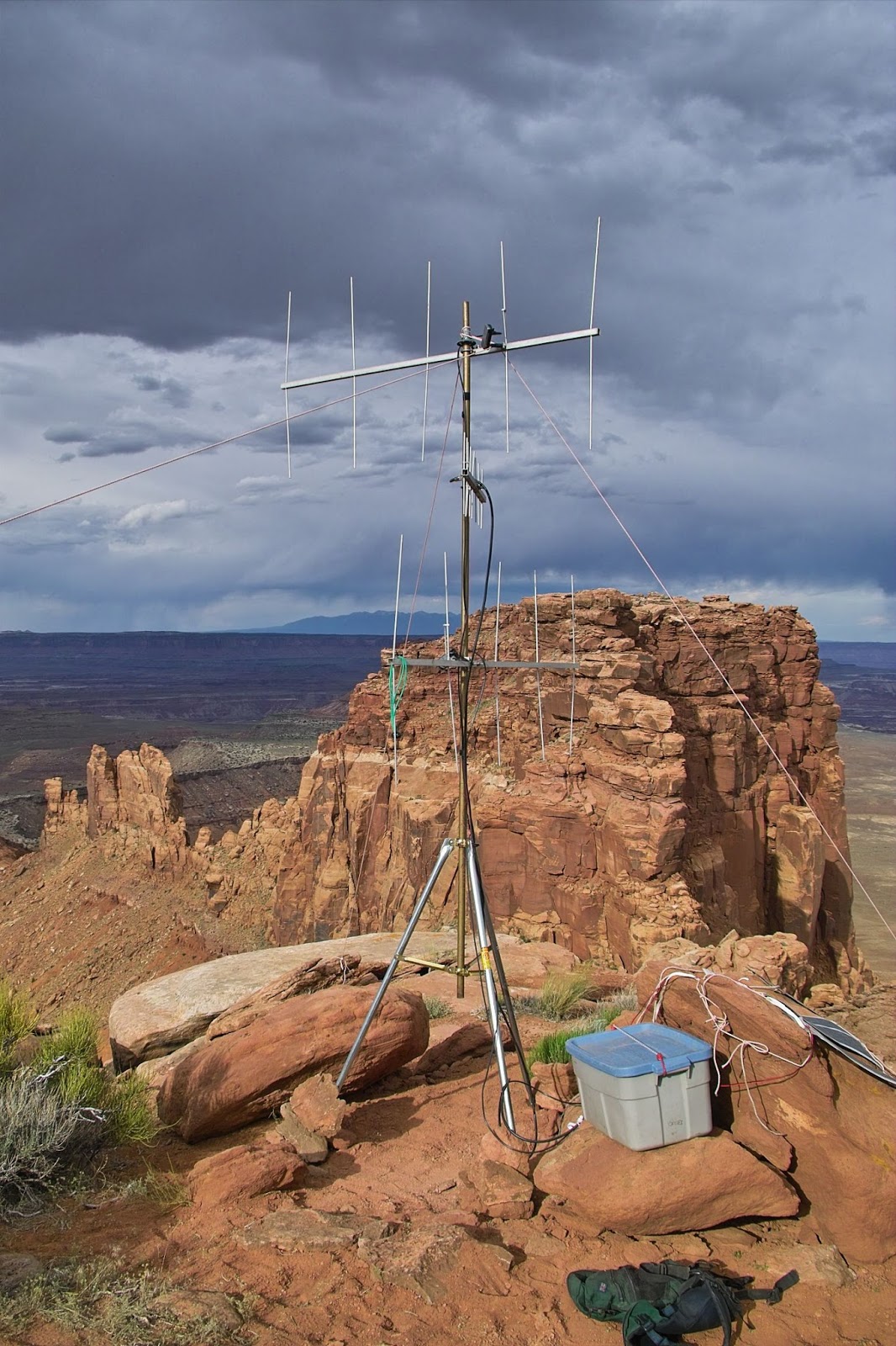
One of the often-overlooked means of improving the coverage of an amateur radio repeater is the use of multiple receivers in a voting configuration. It's often the case that a user can hear the repeater fine, but for whatever reason cannot get back into it - particularly if they are using a portable radio (a handie-talkie) and a compromised antenna, such as a rubber duck antenna. By extending the reach of the receive portion of the system with several geographically disparate receivers on the same frequency the effective, usable coverage can be increased without the need to have a linked repeater system - which may require additional frequencies - and it reduces the necessity of the user to switch between linked repeaters to maintain coverage.
While this article describes a specific 8-channel voting system, it should contain enough information to be able to implement a similar voting controller using other hardware.
Why a voter?
 |
| Figure 1: As-built voting controller board. The small board contains 8 LEDs to indicate which receiver(s) are active and being voted. This voting controller has been in service for about 15 years - and this picture, from a very early digital camera, is lower resolution than one might like. Click on the image for a slightly larger version. |
The use of "extra" receivers also takes into account an important property related to how hams actually use repeaters: When the signal from the repeater is weak, the user will jockey about to find a "hot spot", but when transmitting to the repeater there is no obvious means of feedback to help that same user find reciprocal hot spot - which may or may not be in the same place as for the receive.
A more subtle problem with transmitting is that user naturally places the radio very close to their face which may not be conducive to the best transmitted signal to the repeater and it is the tendency for many people to "drop" their radios a bit, holding the antenna in a way other than vertical - something that often goes unnoticed because, while transmitting, they cannot know the quality of the signal making it to the repeater and adjust their position accordingly.
How it works:
When an FM signal gets weak, it doesn't get quieter - it gets noisier - and we can use this property to determine which, among several receivers, is getting the worst signal(s) - but how do we do this?
 |
| Figure 2: A graph representing the relative amplitude of noise with strong weak FM signals. It is the upward tilt of the noise energy to which "Triangle" noise refers - the angle getting "steeper" as the signal degrades. Also represented is a high-pass filter that removes the modulated audio, leaving only the noise to be detected. From this diagram one can begin to see why pre-emphasizing audio along a curve similar to the "weak signal noise" line can improve weak-signal intelligibility by boosting the high-frequency audio on transmit (and doing the inverse on receive) to compensate for the noise that encroaches on weak signals. |
When the signal is strong, the noise in the background is at quite a low level - often inaudible but as the signal gets weaker, the noise increases in amplitude with the noise at the highest frequencies getting stronger more quickly. Because the audio (e.g. voice) occupies the lower frequencies, if we look only at the higher frequencies, we can detect this noise, more or less independently of the audio.
With amateur radio, however, we don't really us "FM" (Frequency Modulation) per se, but rather "PM" (Phase Modulation) or its equivalent. Saving a complicated explanation and some math, the reason for doing this can be divined by taking another look at Figure 2, above. What one notices is for a given signal - strong or weak - that the amplitude (loudness) of the noise increases with frequency. What this means is that if we were to use "true" FM (whatever that is) on a weaker signal we would hear sharp-timbered noise at higher frequencies creep in to the signal.
In an effort to reduce the effects of this noise, in Amateur Radio the "highs" of the transmitted audio are pre-boosted (called "pre-emphasis") to counteract this effect and on the receive side, they are then "un-boosted" (called "de-emphasis") to restore them to their original frequency response. Because of this "un-boosting" the high-pitched hiss is also reduced and the end result is that when one hears hiss on a weak signal on, say, 2 meters, the noise doesn't have that high-pitched timbre, but it sounds rather like white noise. This has the overall effect of reducing the amount of noise that is perceived on a weak signal, allowing such signals to sound better than they would were it not for this combination of "pre" and "de" emphasis.
 | ||
| Figure 3: A typical squelch circuit found in FM receivers. |
Comparing remote receivers:
The comparison of this noise is easily done if all of the receivers are located in the same place, but what about the typical situation where the receivers may be scattered about, being "connected" to the common point via radio links? The problem with doing this is that the high-pitched noise due to weak signals received via the remote receiver can't easily be transmitted via the link owing to bandwidth concerns - and if we were to try to do this, the squelch on the link receiver itself may be fooled into thinking that the retransmitted noise was actually on the link.
For practical concerns, audio transmitted by an amateur FM transmitter is typically low-pass filtered around 3 kHz so that much of the audio above this would be just noise in the case of a weaker signal, but in a link from a remote receiver we would take this receiver's audio - and its noise - and cut it off, causing us to lose that ultrasonic energy that we'd use to determine the signal quality.
While we would normally use this ultrasonic noise for squelch threshold determination, we can still use what is left to compare two signals. When we listen to an FM signal with our ears, we can tell if it is weak because we hear noise in the background - and the level of this noise is constant, whether the signal is being modulated by the user's speech or not. What this means is that if we simply look at the audio coming from two receivers - and compare them - the one that is weaker will have audio plus noise and will, overall, be a bit louder. If we filter this audio a bit, keeping only the higher-pitched audio - say, that above about 2 kHz - we can more easily make this comparison as most of the audio power of speech is located below 2 kHz, so what we get is a greater percentage of noise and less voice, making the determination easier with simple circuitry.
In the case of the voting controller described, the method of "the lowest noise above 2 kHz is the best signal" is used. This makes it fairly easy to use several signals from disparate receivers to achieve a comparison.
Comment:
There are other methods of determining "which is the weakest signal" - but they all rely on determining which signal is noisiest.
Another method that is used by some voting systems - one that does not rely on high-pass filtering - is an "inverse peak" detector that measures the maximum "quiet-ness" of the signal being received. By determining how quiet the "quiet parts" are (between words, etc.) the best signal may be determined because a noisy signal will have more noise in the quiet parts than a "full quieting" signal. This method typically employs a logarithmic detector to permit useful measurement of the wide dynamics between audio peaks and dead silence.
A simple voting controller:
Figure 4, below, shows the schematic of the voting controller.
To simplify things, this voting controller sits in "front" of an ordinary repeater controller, taking the audio and COS inputs from the various receivers and outputting a single audio and COS signal.
If the repeater system in question uses subaudible tones, it is recommended that "discriminator" audio (e.g. that which has not been de-emphasized) that has not been subject to a squelch or tone detector audio gate be applied to the voting controller from the link receivers as well as any "local" receivers as this will assure that the voted audio will contain the subaudible tone.
By having audio that is not gated by the squelch or tone detector the response of the voting receiver system will be much faster and less-subject to drop-outs as it moves between receivers. Having the subaudible tone detector following the voter will assure faster, more consistent operation, provided that one is careful to make sure that the received phase of the subaudible tones being received by all receivers (e.g. from a single transmitter being heard by all receivers) is as close to the same as possible.
 |
| Figure 4: The schematic of the as-built voting controller. An alternate notch filter is depicted in Figure 6, below. Click on the image for a larger version. |
Microcontroller:
The heart of the voting controller is U8, a PIC microcontroller. Originally, a PIC16C84 was used with an R/C clock oscillator - but this device has long been discontinued, but a minor firmware change was made several years after it was put into service and was replaced with a somewhat more modern, pin-compatible device like a PIC16F628 or PIC16F819. Even a more modern device like a PIC16F88 or a PIC16F1847 could be used with no wiring changes. Because there are no critical timing requirements, the on-board oscillator is used.
The job of the microcontroller is simply to look for active COS inputs and then select the audio sources and do a "noise comparison" to see which one is best and select it.
Audio source selector:
There are really two identical audio source selectors: For the moment we'll talk only about "MUX A" using U2.
U2, a CD4051 CMOS 8-channel MUX is used to select the audio inputs: This device is a genuine 4000-series device and is run from the 12 volt supply to minimize its internal resistance as well as allow the widest-possible swing of the input analog voltages. To interface it with the 5 volt logic of the PIC, Q1-Q3 are used for logic level conversion, the "inverting" of the bits taken care of in software.
For U2 (MUX A) the selected audio also gets buffered by U4D which is passed to the repeater controller as the "voted" audio.
High-pass filter/noise detector:
Each of the MUX's inputs are capacitively coupled and biased at mid-supply (approx. 6 volts) and the selected output is buffered by U5A, a unity-gain follower and then applied to a 3 kHz high-pass filter. This high-pass filter - which doesn't really gain its true effectiveness until below around 2 kHz - removes most of the lower-frequency energy related to the speech, leaving mostly any background noise (hiss) from weak signals.
Following the high-pass filter is a rather high-gain non-inverting amplifier that boosts the filtered audio significantly. Because most of the audio energy of a "clean" signal is below the 2-3 kHz range, the total amount of energy that remains is quite low, but by amplifying it, even low amounts of "hiss" can be detected. During normal use, this noise amplifier will often be driven into clipping, but that's OK as a poorer-quality signal (e.g. noisier) will still have, overall more total audio energy.
The energy from this amplifier is rectified and smoothed by diodes D1 and D2 - with a small amount of DC bias for the diodes provided by R25, a 1 Megohm resistor which slightly improves low-signal sensitivity - particularly when several signals being received via the receiver(s) are at or near full-quieting.
Signal quality comparator:
At this point it's worth mentioning again that there are two audio paths - the "MUX A" path input via U2 mentioned above, and an identical audio path that uses U3 and the same amplifier and noise detector arrangement: The only difference is that it is only the audio being selected by "MUX A" path (via U2) that is passed to the repeater controller, so that is always going to be the "best" signal if more than one is present.
Having two separate "noise" voltages, a simple analog comparator, U6, is used to see which one is the "noisiest". In this case, an LM311 comparator is used, relying on microcontroller's internal pull-up resistor to provide a logical "high" signal - and this handily does the logic level conversion as well. An LM339 would have worked fine, but since we need only a single comparator - and the '339 has four - I just used an LM311. In a pinch it's possible that an op-amp could have been used as a detector, but care must be taken to assure that the chosen op amp will work properly with signals that are very near ground and can go up near the positive supply rail.
Comment:
The originally-used PIC16C84 did not have a built-in A/D converter or comparator, but many more modern PICs do - and either one could be used in this case to compare the two signal paths' noise voltages. Because the more modern processor was a retrofit for the original 'C84, there was no reason to get rid of the comparator.
If an internal A/D converter or comparator is used, be aware that the analog voltages from the noise detectors could easily exceed the maximum 5 volt rail of the processor so appropriate clipping/scaling should be applied.
COS Mux:
For each of the (up to) eight receivers, there is a corresponding "COS" input - that is, a line that is pulled to ground (typically by an open collector or drain) when that receiver picks up a signal that opens its squelch. To convey these eight signals to the microcontroller, U1, a 74HC168 8-input shift register is used. During normal operation the controller will strobe the current states into the register via the "/PL" line and then, using the clock and data lines, read them serially - all using just 3 processor pins instead of 8.
Note that there are two resistors on each input of U1: R16(a-h) being used to pull the input up to 5 volts and series resistors R17(a-h) used to protect the input of U1 in the event that the COS input happens to go above 5 volts.
PTT Output:
If any COS input is active, the PTT signal from pin 2 of U8, the microcontroller goes high. This signal then enables Q7 an NPN transistor that is used to pull the repeater controller's PTT line low.
Active channel indicator:
To indicate which receiver's audio is currently being passed to the repeater controller, U9, a 3-8 decoder - is used, monitoring the address lines for MUX A. If no COS signals are active, U9's "E3" input, which is tied to the same microcontroller pin that asserts the PTT to the repeater controller, goes low, turning off all of the LEDs.
Comparing signals:
At this point it's worth talking about how the signals are compared and voted on.
MUX A is always used by the best receiver after voting so that it will be passed to the repeater controller. MUX A is therefore always used as the basis of comparison to any other channels that might be active.
- If there is one receiver active as indicated by its COS line, MUX A is used to select it, which pipes the audio to the output, to the repeater controller.
- If there are two receivers active, the first one to have been detected active is set to MUX A and the second one is set to MUX B.
- If the receiver on MUX B is "quieter" than the one on MUX A, the output of U6 will be generally low because of higher noise coming from the MUX A channel. In this case, the microcontroller will swap the two signals, putting the "better" one on MUX A where it can be passed to the repeater controller.
- If there are more than two receivers active, MUX B is used to switch between these other active receivers, comparing them to that "active" receiver on MUX A: If another of these others suddenly has a better signal, it's immediately moved to MUX A where it can be output to the repeater controller.
- If the COS for the receiver on MUX A suddenly disappears but there is at least one other signal present, the lowest-number signal is immediately switched to MUX A and the voting process resumes.
- If there are suddenly no active COS signals, the output PTT signal from the microcontroller is dropped immediately.
(Note that the source code, in "C", is included below if you wish to "play along".)
In the "main()" loop of the software, the "update_sr()" function is called every time it executes, making certain that the COS inputs are updated very frequently.
When the microcontroller is in it's "idle" state (no active COS input) both the "A" and "B" audio MUXes are set to receiver 1. Besides being a convenient starting point, this allows easier adjustment of the noise detector circuits as they would be fed with the same signal, making it very easy to set them identically.
If, after being idle, a COS input goes active, the first one that the it runs across is assigned to MUX A and the PTT output is set active. After assigning the first signal to MUX A - which causes that receiver's audio to be passed to the repeater controller - another portion of the code is then executed that looks for other active COS inputs.
If one or more active COS inputs are detected, it assigns the first one to MUX B. Allowing time to for the readings to settle, the controller then does a bit of simple averaging over the next 25 loop cycles (which takes about 25 milliseconds) to see if the signal on MUX B seems to be "better" than the one on MUX A.
If the signal currently on MUX B is better, MUX A is switched to this input. If the signal on MUX B is not better, the controller sequentially switches MUX B to other currently-active COS inputs and makes the same comparison.
In this same loop, an eye is kept on the COS status of the channel to which MUX A is currently set: If this COS goes inactive, the code immediately re-scans to find another active COS input, assigning it to MUX A to make sure that audio from an active receiver is being passed to the repeater controller. If it is determined that there are no active COS inputs, the PTT line is immediately dropped so that the repeater controller may do its normal "hang time" operations.
For the original implementation I used a PIC microcontroller because I've long been familiar with them and have had the appropriate development tools, but it could be done using something like an Arduino if they'd existed when I first built this: Even the cheapest, low-end UNO would even be overqualified for the task!
To do this, one would simply substitute the Arduino and its I/O pins for U8: While the Arduino has available comparators and A/D converters, it would be almost as easy to use an outboard comparator rather than trying to get rid of it unless, as noted above, you are prepared to scale voltage appropriately.
It is possible for the entire device to run from a single 5 volt source, but if this is done rail-to-rail input and output op amps are strongly recommended and very close attention should be paid to the peak-to-peak voltage swings of all the analog signals: Worst-case is typically the "no signal" condition where the radio is outputting noise and if an analog voltage goes above the supply voltage or "below" ground (as can happen with capacitive coupling) many analog MUXes will spuriously conduct this noise into other, de-selected channels, causing very annoying "popping" in the audio.
Using a "voting" tone:
Many voting systems include a tone that is sent along the circuit when no signal is present - and for best performance, such is recommended here.
For example, each remote receiver is configured with a 3.5kHz oscillator that is activated when the squelch closes and the audio being receive and then transmitted along the link to the voting site is muted - followed by a short (half-second or so) "hang time" with the remote receiver/link transmitter transmitting only this tone.
The reason for this is to minimize the number of "noise bursts" that one might hear as a user popped in and out of more than one receiver. For example, if the user was "weak but solid" into receiver "B" but was popping in and out of "A" - often with a good signal - then the voter would select receiver "A" when the user was solid into it, but reverting back to "B" when the signal dropped out.
If the link transmitter were to key on and off every time the user dropped in and out of "A", the link receiver at the voting site would get a burst of squelch noise every time - and this would inevitably come across the link in the instant before it was detected, making the signal sound more "multipathy" and noisy than it really was.
If, instead, a strong 3.5kHz tone was sent down the link as soon as receiver "A" dropped out, the voter would detect this tone as if it were noise - but much more strongly so - and the voter would immediately switch away from it, to receiver "B", handily avoiding that burst of noise that would otherwise be transmitted from both the receiver "A" and its link transmitter dropping out at the same time.
This typically works because, in a voter system, one rarely drops instantly out of one receiver, but in the case of multipath this fade can happen very quickly: Having the tone switch on helps make the voter switch more quickly with the squelch on the receiver "A" closing before the signal is completely gone.
Having this tone does mean that to those listening, a brief burst of that tone will come through - particularly if only one receiver is in use: In that case, there is no "better" receiver to switch away from which means that the 3.5 kHz tone will blast out during the link transmitter's brief hang time.
To prevent this ear-piercing tone from being obnoxious, the schematic in Figure 4 includes a notch filter to reduce this 3.5 kHz tone. As mentioned in the notes below this small diagram, it is strongly recommended that the pairs of capacitors and resistors be carefully matched to obtain the best notch depth (which should be well over 25dB). It is suggested that this filter - or one of similar function - be placed on the audio output before it is passed along to the repeater controller.
Block diagram of an example system:
In Figure 5, below, is a block diagram of an example system.
 |
| Figure 5: Block diagram of an example voting repeater system with two remote receivers and one receiver co-located with the transmitter. An example of a "tone decoder module" is given in Figure 6, below. Click on the image for a larger version. |
The remote receiver (one of several, perhaps) is located at a site that offers complementary coverage - or perhaps to fill in a particularly badly-covered area where users may be able to hear the repeater well (perhaps noisily) or in an area where it may be advantageous to have a "local" receivers to allow good coverage via low-power handie-talkies (say, an area where public service events are commonly held.) This remote site should include a rudimentary repeater controller capable of producing hang-time, legal identification and time-out should a signal get "stuck" on the receiver's input.
If the system is to be used with a subaudible tone it is recommended that the tone decoder not be located at the remote receiver, but rather that it be normal "COS squelch" and that the tone be able to be passed directly from the receiver to the transmitter: Many receivers and transmitters have high-pass filters to prevent exactly this so it may be necessary to select the gear carefully and/or make some modifications to allow this. The reason for this is that subaudible tones are quite slow to be decoded meaning that if a signal is weak or choppy, a lot of content can be lost during these portions of a transmission as the already-slow tone decoder will be even slower to respond if the signal is noisy. If a subaudible tone is decoded at the link transmitter, expect there to be more "holes" in the audio as users transition between the two receiver sites than otherwise!
When the COS of the received signal drops, a 3.5 kHz tone is switched in instantly to "un-vote" the signal from that receiver: This "loud" tone will instantly be detected by the voting controller as one that is "bad" (e.g. lots of high-frequency content - a stand-in for the noise of a poor signal) and it will vote "away" from this receiver - assuming that another receiver is still active. If no other receiver is active, the notch filter (in the voting controller) will remove this tone so that users can't hear it during the remote site's transmitter's hang time.
The reason for the hang time (where the remote site is transmitting only a tone) is to reduce the amount of audible "chop" that might be heard when a signal is dropping in and out of a receiver. By having a bit of hang time (with tone) the voter will be given a chance to "switch away" from it when a signal drops without there being the burst of squelch noise when the link transmitter drops, before the receiver at the voter site's squelch closes.
Repeater transmitter site:
At the repeater's transmitter site there may be one or more "link" receivers - but there may also be a "local" receiver. As seen, the voting controller sits between the receivers and the repeater controller, the idea being that the voting controller will make the multiple receivers look like a single receiver.
In the simplest case, all receivers simply connect to the voting controller via their (unsquelched!) audio and their COS lines: As with the remote receivers, the link receiver should be COS-only with no subaudible tone for the same reasons as mentioned above. The subaudibletone decoder should only be present in the signal after the voting controller to provide the best response to rapidly-changing signals.
"Voting tone":
To prevent the shrill 3.5 kHz tone from blasting through the repeater during the hang time of a link receiver, the 3.5 kHz notch filter is depicted in the audio path between the output of the voting controller and the repeater controller. At 3.5 kHz, this notch will have little or no effect in the quality or timbre of the received signals.
 |
| Figure 6: An example of a tone detector that can be adjusted to 3.5 kHz along with another example of a notch filter for the tone. This diagram also includes a de-emphasis circuit in the event that were needed. Note that all capacitors NOT used for power supply bypassing (e.g. those in the de-emphasis, notch filter and tone decoder) must be temperature- stable plastic capacitors and not disk ceramic. Click on the image for a larger version. |
It should be noted that if there is a direct wire connection between the receiver and the voting controller - as would be the case for a local receiver - none of this 3.5 kHz nonsense is required as there is, by definition, no extra "squelch noise" burst on that receiver as would happen on the remote receiver when its link transmitter un-keyed.
Final comments:
If you do plan to have an analog voter of any kind, also note that you must use a purely-analog receiver: While tempting, radios that use "all in one" chips (such as Baofengs and other imported brands) are probably not usable as they tend to have a bit of delay, they may have no easy way to defeat the filtering of subaudible tones, and they also tend to automatically switch in a low pass filter on noisy signals - something that would mess up any comparison that you would hope to do - and this assumes that they actually have a "COS" output that is actually fast enough to be useful!
What about voting for a digital system?
While implementing a voting repeater system for an analog repeater is straightforward, the same cannot be said for digital signals. To an extent, a radio could "know" of several different linked systems in a given coverage area, but having several systems not only requires a lot of resources (gear, frequencies) but it is arguably less convenient and less effective than having a voting system to increase the "grasp" of a receive system. In theory, one could have very carefully designed receive systems that "seamlessly" switch between two receivers without corrupting bits (very careful attention to phase and timing would be required!) but the noise-like nature of digital signals makes their direct quality comparison a bit more difficult.
If some sort of voting system is used, it might also have individual digital demodulators at each site and then convey that digital signal to a more complex voting system that performs re-timing of the received signals and then monitors the apparent error rate, feeding the "best" result to the original repeater: Such a system is beyond the scope of this article.
Addendum:
* * *
Source code:What follows is source code, in "C", targeted for a now-ancient version of the CCS compiler. This version of code assumes the use of a PIC16C84 microcontroller that used external R/C oscillator components. (I couldn't find the version updated for the newer processor - but the changes required were very minor.)
It is not expected that one would use this code as-is, but rather use it as an example as to how the logic worked so that it could be applied to other platforms.
This code is supplied as-is with no expressed or implied warranty regarding usefulness or fit for any purpose.
* * *
/*
This code is for an 8-input voting controller. There are two noise-detect channels on 8-input
MUXes: Channel A is the "primary" channel: This channel, when selected, outputs the selected
channel's audio. Channel B is used to compare against channel A and if it is *better* than
channel A, then THIS channel gets transferred to A (thereby selecting it as the audio source.)
Note that ONLY those channels with active COS are compared.
Revision History:
0.01 20000610 Started work
0.02 20000611 First operational version (I think...)
Notes:
- It is highly recommended that the audio inputs from the various
receivers be UNMUTED by the COS.
- When an input signal is active, the respective input COS signal goes
LOW. This is usually accomplished with an open collector at the
receiver.
- Unless ALL of the receivers are local, the audio inputs MUST
be de-emphasized.
- All audio inputs are to be adjusted identically at their
respective receivers. The more closely matched, the less difference
will be heard when the voting occurs.
- This voting controller does NOT affect the audio passed through it in
any way (assuming that the amplifiers aren't clipping) other than by
selection of the audio source. Once the receivers are adjusted for
EQUAL output levels, THEY SHOULD NOT BE READJUSTED! Doing so will
require complete realignment of the system/voting controller. If
additional transmit deviation is needed, this should be done by
adjusting the CONTROLLER and *NOT* the the receivers!
Adjustment procedure:
- This procedure assumes that the highest audio input level will occur
with squelch noise.
- The following test points are used:
TP1 - Noise detector Channel A output voltage
TP2 - Noise detector Channel B output voltage
TP3 - Noise Channel A output level (highpass audio)
TP4 - Noise Channel B output level (highpass audio)
This procedure is to set the noise channel outputs (TP3 and TP4) to the
highest level possible (without excessive clipping) so that, for the
same signal, the detector voltages (on TP1 and TP2) are as close to
identical as possible.
1) MAKE SURE THAT ALL RECEIVER OUTPUTS ARE MATCHED IDENTICALLY WITH THE
SAME AMOUNT OF DEVIATION! That is, with 3 KHz of deviation, all
receivers should be set to output the SAME audio level.
Additionally, the audio equalization should be matched as closely as
possible for all receivers.
2) With *no* COS signals active and with (unsquelched) audio going into
RX audio 1, connect an oscilloscope to TP3 (noise Channel A Highpass
output) and adjust potentiometer RA for the maximum audio level that
results no or only a slight amount of clipping.
3) Move the oscilloscope to TP4 and adjust potentiometer RB for the same
level as on TP3.
3) Connect a voltmeter to TP1 (MUX Channel A noise detector output) and
note the voltage. It will bounce a bit as the noise, so note the
"average" voltage reading.
4) Move the voltmeter to TP2 and adjust it to the same average voltage
as read on TP1.
5) Using the oscilloscope, compare the outputs at TP3 and TP4. If one
is much higher than the other, reduce the highest one somewhat and
set the other channel to the same using a similar procedure to the
above.
6) When done, make sure that TP1 and TP2 are approximately equal
voltages (i.e. closer than 0.1 volts of each other.)
*/
#OPT 9
#include <16c84.h> // define use of 16c84a
#define PORT_A_ADDR 0x05 // port A address
#define PORT_A_TRIS 0b00001 // port A I/O mask (LSB in, RA1-RA4 out)
#define PORT_B_ADDR 0x06 // port B address
#define PORT_B_TRIS 0b10000000 // port A I/O mask (LSB and MSB in, others out)
#define WAIT_TIME 7 // time, in milliseconds, that we should
// wait before starting to make any decision
#define VOTE_TIME 25 // The number of "cycles" through the quality
// decision loop. Each cycle takes about 1
// millisecond
#define QUAL_THRESH 15 // this is the number "good hits" that are
// required during the "VOTE_TIME" to decide
// if "this" one is really better
#byte PORT_A = 5
#byte PORT_B = 6
#fuses RC, WDT, NOPROTECT, PUT
// RC Oscillator, watchdog, no code protect, Power Up Timer, no
//brownout protect
#use delay(clock=225000, RESTART_WDT) // 225 KHz = 33k & 82pf
#use fast_io(a) // set port A for fixed-mode of I/O direction
#use fast_io(b) // set port B for fixed-mode of I/O direction
// System definitions:
#bit SR_INDAT = PORT_A_ADDR.0 // Serial data from parallel-input shift register
#bit SR_CLK = PORT_A_ADDR.1 // Shift register clocking
#bit SR_PLOAD = PORT_A_ADDR.2 // Shift register parallel load
#bit COS_OUT = PORT_A_ADDR.3 // "voted" COS output (1 = active)
// PA4 is reserved
//
#bit MUXA_A = PORT_B_ADDR.0 // audio mux A LSB
#bit MUXA_B = PORT_B_ADDR.1 // audio mux A
#bit MUXA_C = PORT_B_ADDR.2 // audio mux A MSB
#bit MUXB_A = PORT_B_ADDR.3 // audio mux B LSB
#bit MUXB_B = PORT_B_ADDR.4 // audio mux B
#bit MUXB_C = PORT_B_ADDR.5 // audio mux B MSB
// PB6 is reserved
#bit COMP_IN = PORT_B_ADDR.7 // signal quality comparator (0 = "B" is *BETTER* than "A")
byte cos_data;
#ZERO_RAM // This macro causes code to wipe all memory locations
// This function gets data from the input shift register
update_sr(void)
{
char x;
SR_CLK = 0; // initialize sr clock
SR_PLOAD = 0; // load data into shift register
SR_PLOAD = 1; // 'freeze' data in input shift register
cos_data = 0; // clear Carrier Operated Squelch input shift register
for(x = 0; x <=7; x++) {
SR_CLK = 0;
cos_data <<= 1; // shift next bit of input data into position
if(SR_INDAT) {
bit_set(cos_data, 0); // Set the LSB of "cos_data" (this is a one-instruction PIC operation) if SR output is high
}
SR_CLK = 1; // shift the data in
}
}
void setmux_a(byte b) // this function sets MUX channel A
{
byte temp;
temp = PORT_B; // read port B output register
temp &= 0b11111000; // clear 3 LSBs for MUX A
b ^= 0xff; // invert contents to account for inversion of level converter
b &= 0b00000111; // make sure nothing is in anything but bottom LSBs
temp |= b; // overlay MUX A data
PORT_B = temp; // send it out
}
void setmux_b(byte b) // this function sets MUX channel B
{
byte temp;
temp = PORT_B; // read port B output register
temp &= 0b11000111; // clear the 3 bits for MUX B
b <<= 3; // shift the current MUX data to match bit positions
b ^= 0xff; // invert to compensate for level conversion
b &= 0b00111000; // make sure nothing is in this but the correct bits...
temp |= b; // overlay MUX A data
PORT_B = temp; // send it out
}
void main(void)
{
byte x; // multipurpose counter
byte qualcnt; // "quality" counter
byte mux_a; // holder/counter for mux_a
byte mux_b; // holder/counter for mux_b
short cos_scanflag; // flag bit used in scanning for COS activity
short recheck_flag;
setup_counters(RTCC_INTERNAL, WDT_144MS);
SET_TRIS_A(PORT_A_TRIS); // set I/O direction for ports
SET_TRIS_B(PORT_B_TRIS);
//
PORT_B_PULLUPS(TRUE);
COS_OUT = 0; // clear output COS line...
mux_a = 0; // initialize MUX selectors
mux_b = 0;
recheck_flag = 0;
update_sr(); // grab data (to initialize shift register)
while(TRUE) {
update_sr(); // get current COS status
restart_wdt();
if(cos_data == 0xff) { // is there *NO* COS activity? (bits go low when COS is active)
COS_OUT = 0; // yep - indicate such.
mux_a = 0; // always put both mux channels on 0
setmux_a(mux_a); // when no COS inputs are active...
mux_b = 0;
setmux_b(mux_b);
}
else { // there *is* COS activity. Find out which one it is...
if(!COS_OUT || recheck_flag) { // the output COS is not yet active *or* ONE
// became inactive, we need to find one that
// is active is hearing the signal
recheck_flag = 0;
mux_a = 0; // always make sure it we are starting out at zero...
mux_b = 0; // init mux B count
cos_scanflag = 1; // init flag used for scanning COS bits
while(cos_scanflag) { // this keeps happening while the flag is set
if(!bit_test(cos_data, mux_a)) { // is it *THIS* bit that is active?
setmux_a(mux_a); // yes - set MUX to this address
COS_OUT = 1; // set COS activity
cos_scanflag = 0; // clear flag so we don't go thru this again
}
else {
mux_a++; // bump count to next input
if(mux_a > 7) { // did we exceed our maximum count?
cos_scanflag = 0; // yes - we bail out...
COS_OUT = 0;
}
}
}
}
else { // COS *IS* active - lets look at other inputs to see if they are active
if(!bit_test(cos_data, mux_b)) { // is *this* COS bit active?
setmux_b(mux_b); // change MUX to new channel...
delay_ms(WAIT_TIME); // wait for comparator to settle
qualcnt = 0;
for(x = 0; x < VOTE_TIME; x++) {
delay_ms(1);
if(!COMP_IN) { // is this NEW a better signal?
qualcnt++;
}
}
if(qualcnt >= QUAL_THRESH) { // has the signal been better for enough samples?
mux_a = mux_b; // yes - set both MUXes to the same place...
setmux_a(mux_a); // set output to new signal put it there...
}
COS_OUT = 1; // make SURE we have COS output enabled
}
mux_b++; // bump to next mux count
mux_b &= 0b00000111; // mask mux address
if(mux_b == mux_a) { // are we attempting to look at the same input?
if(bit_test (cos_data, mux_b)) { // is *this* COS bit INactive now?
recheck_flag = 1; // yes - this signal went away - get new COS
}
mux_b++; // yes - go to the *next* address
mux_b &= 0b00000111; // mask mux address
}
}
}
}
}
This page stolen from ka7oei.blogspot.com
[End]