Monday, July 31, 2023

A solid state replacement for an old radio's "vibrator" (Wards Airline 62-345)

Figure 1:
The front of the Wards Airline 62-345 with its rather
distinctive "telephone dial" tuning dial.
It's powered up and running from 12 volts!
Click on the image for a larger version.
Quite some time ago - a bit more than a decade - a friend of mine came to me with an old "Farm" radio - a Wards Airline 62-345.  This radio - from the 1930s - was designed to run from a 6 volt positive ground battery system  such as that which one might find in tractors and cars of that vintage.

How high voltage was made from low voltage DC in the 30's

As the technology of the time dictated, this radio has what's called a "vibrator" inside - essentially a glorified buzzer - that is used as a voltage chopper along with a transformer to convert the 6 volts from the battery to the 130-150 volts needed for the plates of the tubes within.  Not only did this vibrator do the chopping for the high voltage, but it also performed the duty of synchronously rectifying the AC waveform from the transformer as the pulses from it would naturally be in sync with the motion of the moving reed, briefly connecting the output of the transformer to the input of the high voltage DC supply when the voltage waveform from it was at the correct polarity.

These devices, as you would expect, don't have a particularly long lifetime as they are constantly buzzing, making and breaking electrical contact and causing a small bit of arcing - something that will inevitably wear them out.  Even if the contacts were in good shape, the many decades of time that have passed will surely cause these contacts to become oxidized - particularly since these devices are in rubber-sealed cans (to minimize noise and vibration) and the out-gassing of these materials is likely of no help in their preservation.

Figure 2:
The chassis of the radio.  The vibrator is in its original
can in the far right corner.
Click on the image for a larger version.
Such was the case with this radio.  Often, the judicious application of percussive repair (e.g. whacking with a screwdriver) can get them going and if the contacts are just oxidized, they will often clean themselves and work again - at least for a while.  In this case, no amount of whacking seemed to result in reliable operation, so a modern, solid-state approach was needed.

The solid-state replacement

As mentioned earlier, the job of the vibrator was to produce a chopped DC waveform, apply it to a transformer for "upping" the voltage and then use a separate set of contacts to perform synchronous rectification - and our solid-state replacement would need to do just that.  That last part - rectification - was easy:  Just two, modern diodes would do the job - but chopping the DC would require a bit more circuitry.

The owner of this radio also had a few other things in mind:  He changed it from 6 volts, positive ground to 12 volts, negative ground so that it could be readily operated from this more-common power scheme.  The change to 12 volt filaments required a bit of work, but since all of the tubes were indirectly heated, the filament supply could be rearranged - but some tubes had to be changed to accommodate different filament voltages and currents as follows:

  • Oscillator and detector:  This was originally a 6D8 (6.3v @ 150mA) and it was replaced with a 6A8 (6.3V @ 300mA).  Other than filament current, these tubes are more or less the same.
  • IF Amplifier:   The original 6S7 (6.3v @ 150mA) was retained.
  • 2nd Detector/AVC/1st Audio:  The original 6T7 (6.3V @ 150mA) was retained.
  • AF Output:  The original 1F5 (2.0v @ 150mA) was replaced with a 6K6 (6.3v @ 400mA).  The latter is a pentode, requiring a bit of rewiring and rebiasing to replace the original triode.
  • Magic Eye tube:   The original 6N5 (6.3v @ 150mA) was replaced with a 6E5 (6.3v @ 300ma) - which is also more sensitive than the 6N5, giving a bit more deflection.

The 6T7 (150mA), 6A8 (300mA) and the #47 dial lamp (6.3v @ 150mA) are wired in parallel on the low side with one end of the filament grounded while the 6K6 (400mA), 6S7 (150mA) and 6E5 (300mA) are wired in parallel on the high side with one end of the filament connected to +12 volts.  You might notice a current imbalance here (600mA on the low side with 850mA on the high side) but this is taken care of with the addition of 30 ohms of resistance between the midpoint of the filament string and ground to sink about 200mA getting us "close enough".

He also did some additional rebiasing and other minor modifications - particularly for the rewiring of the AF Output from the original 1F5 to a 6K6 as he swapped a triode for a pentode - which was then  wired as a triode.  The total current consumption of the radio at 13 volts is 1.6 amps - a bit more than half of that being the filament and pilot lamp circuits meaning that about 10 watts of power is being used/converted by the vibrator supply and consumed by the idle current of the audio output and other tubes.

The other issue with the 6 to 12 volt conversion is that of the primary of the high voltage transformer:  This transformer is center-tapped with that connection going to the "hot" side of the battery (which was originally at -6 volts) - but what this really means is that there's about 12 volts from end-to-end on the transformer at any instant.  We can deal with this difference simply by driving the transformer differently:  Rather than having the center tap "hot" with the DC voltage and alternatively grounding one end or the other as the vibrator did we can simply disconnect the transformer's center tap altogether and alternately apply 12 volts to either end, reversing the connection electronically to preserve the original voltage ratio between primary and secondary.

This feat is done using an "H" bridge - an array of four transistors that will do just what we need when driven properly:  Apply 12 volts to one side and ground the other - or flip that around, reversing the polarity.

Consider the schematic below:

Figure 3:
Solid state equivalent of a vibrator supply.  This version uses an "H" bridge, suitable for
the conversion of a 6 volt radio to 12 volt operation as detailed in the text.
Click on the diagram for a larger version.

This diagram shows a fairly simple circuit.  For the oscillator we are using the venerable CD4011 quad CMOS NAND gate with the first two sections wired to produce a square wave with a frequency somewhere in the 90-150 Hz region - the precise value not being at all critical.  The other two sections (U1c and U1d) take the square wave and produce two versions, inverted from each other.

Figure 4:
The top (component side) of the circuit.  This is built on a
piece of phenolic prototype board.
Click on the image for a larger version.
The section of interest is the "H" bridge consisting of transistors Q1 through Q4 wired as two sets of complimentary-pair Darlington transistors.   Here's how it works:

  • Let us say that the output of U1c is high.  This causes the output of U1d to be low as it's wired as a logic inverter.
  • The output of U1c being high will cause the top transistor (Q1 - a PNP Darlington) to be turned OFF, but at the same time the bottom transistor of this pair, Q2, will be turned ON, causing the connection marked "PIN 1" to be grounded.
  • At the output of U1d - being low - we see that the bottom of this pair of transistors, Q4, is turned OFF, but the top transistor Q3 is turned ON causing V+ (12 volts) to appear at the connection marked "PIN 5".
  • In this way, the low-voltage primary of the transformer has 12 volts across it.
  • A moment later - because of the oscillator - the output of U1c goes low:  This turns off Q2 and turns on Q1 - and since this also causes the output of U1d to go high this, in turn, turns off Q4 and turns on Q3.  All of this causes "PIN 5" to now be grounded and "PIN 1" to be connected to V+ - thus applying the full 12 volts to the transformer in reverse polarity.

Also shown are D1 and D2, the solid-state replacements for the synchronous rectifier of the original vibrator.  While this could be a pair of high-voltage diodes (>=400 volts) we simply used half of a full-wave bridge rectifier from a junked AC-powered switching supply.  Finally, resistor R3 and capacitor C2 form a filter to keep switching noise and high-voltage spikes out of the power supply of U1 to prevent its destruction - a sensible precaution!

Now some of you might be concerned about "shoot through" - the phenomenon when both the "upper" transistors (Q1, Q3) might be on - if only for an instant - at the same time as the "lower" transistors (Q2, Q4) as the switching is done.  While this may happen to a small extent, it has negligible effect - particularly at the low switching frequency where this effect would constitute a very minuscule percentage of the switching period:  This circuit is efficient enough that no heat sinking is required on transistors Q1-Q4 and they get only barely warm at all.  Were I to build it again I might consider ways to minimize shoot-through, but this would come at the expense of simplicity which, itself, is a virtue - and since this circuit works just fine, would probably be not worth the effort.
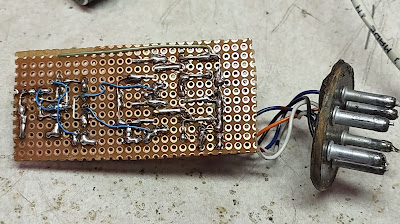
Figure 5:
The bottom (wired side) of the circuit with flying leads
connecting to the original base socket.
Click on the image for a larger version.

These days one might consider building this same type of circuit using MOSFETs instead of Darlington transistors (e.g. P-channel for Q1 and Q3, N-channel for Q2 and Q4) and this should work fine - but the Darlington transistors were on hand at the time that this circuit was built and very easily driven by U1 - and the bipolar transistors are - at least in this case - arguably more rugged than the MOSFETs would be - particularly since there was no need to include a "snubber" network to suppress switching transients that might occur.  It's also worth noting that while standard MOSFET transistors would work fine for a 12 volt supply, you'd have to be sure to select "low gate threshold" devices to work efficiently at 6 volts or lower - something that would not really be an issue with the bipolar Darling transistors shown here.

This circuit is simple enough that it was wired onto a piece of phenolic prototyping board, snapped down to a size that will nicely fit into the original can that housed the vibrator.  To complete the construction, the top of the can - which was originally removed by careful filing and prying - was glued into its base using "shoe goo" - a rubber adhesive - keeping the board protected, but also allowing it to be easily disassembled in the future should modification/repair be necessary.

To be sure, the Internet is lousy with this same sort of circuit, but this version has worked very well.

What about the center tap version of the solid state vibrator?

You might ask yourself "what if we don't want to rewire a 6 volt radio to 12 volts?"  As noted previously, the boost transformer in the radio had its center tap connected to the "hot" side - which, in this case, would have been the negative terminal (because many vehicles had 6 volt, positive grounds at the time).  This circuit could be easily modified for that as you'd need only "half" an "H" bridge and the resistors driving the transistors would be changed to a lower value - perhaps 2.2k.  Depending on whether the it was positive-ground or negative ground, or whether the center-tap was grounded or "hot" - this would dictate whether you needed the PNP or NPN halves of the H-bridge.

(If you have a specific need, feel free to contact me by leaving a comment.)

* * * 

This page stolen from ka7oei.blogspot.com


 [END]


Wednesday, July 19, 2023

Modifying an "O2-Cool" battery fan to (also) run from 12 volts

A blog posting about a fan?  Really?

Why not!

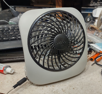
Figure 1:
The modified fan on my cluttered workbench, running
from 13 volts.
The external DC input plug is visible on the lower left.
Click on the image for a larger version.

This blog post is less about a fan, but is more of example of the use of a low-cost buck-type voltage converter to efficiently power a device intended for a lower voltage than might be available - in this case, a device (the fan) that expects 3 volts.  In many cases, "12" volts (which may be anything from 10 to 15 volts) will be available from an existing power source (battery, vehicle, power supply) and it would be nice to be able to run everything from that one power bus.

Background

Several years ago I picked up a 5" battery-operated DC fan branded "O2 Cool" that has come in handy occasionally when I needed a bit of airflow on a hot day.  While self-contained, using two "D" cells - it can't run from a common external power source such as 12 volts.

Getting 3 volts

Since this fan uses 3 volts, an obvious means of powering it from 12 volts would be to simply add a dropping resistor - but I wasn't really a fan of this idea (pun intended!) as it would be very wasteful in power and since doing this would effectively defeat the speed switch - which, itself is just a 2.2 ohm resistor placed in series with the battery when set to "low".

The problem is that the fan itself pulls 300-400 mA on high speed.  If I were to drop the voltage resistively from 12 volts (e.g. a 9 volt drop) - and if we assume a 300mA current - we would need to add (9/0.3 = ) 30 ohms of series resistance to attain the same speed on "high" as with the battery.  The "low speed" switch inserts a 2.2 ohm resistor, and while this works with its original 3 volt supply, adding this amount to 30 ohms would result in a barely noticeable difference in speed, effectively turning it into a single-speed fan.  By directly supplying the fan with something close to the original voltage, we preserve the efficacy of the high/low speed switch.

Fortunately, there's an answer:  An inexpensive buck converter board.  The board that I picked - based on the MP1584 chip - is plentiful on both EvilBay and Amazon, typically for less than US$2 each.  These operate at a switching frequency of about 1 MHz and aren't terribly prone to cause radio interference, having also been used to power 5 volt radios and even single-board computers (such as the Raspberry Pi) from 12 volts without issues.

These buck converters can handle as much as 24 volts on the input and provide up to 3 amps output - more than enough for our purpose - and can also be adjusted to output about any voltage that is at least 4 volts lower than the input voltage - including the nominal 3 volts that we need for the fan.

An additional advantage is the efficiency of this voltage conversion.  These devices are typically 80% efficient or better meaning that our 300 mA at 3 volts (about 0.9 watts of power) would translate to less than 100mA at 12 volts (a bit more than a watt).  Contrast this to the hypothetical resistive dropper discussed earlier where we would be burning up nearly 3 watts in the 30 ohm resistor by itself!

Implementation

One of my goals was to retain the ability of this fan to run at 3 volts as it would still be convenient to have this thing run stand-alone from internal power.  Perhaps overkill, but to do this I implemented a simple circuit using a small relay to switch to the buck converter when external power was present and internal power when it was not, rather than parallel the buck converter across the battery.

If I never intended to use the internal "D" cells ever again I would have dispensed with the relay entirely and not needed to make the slight modifications to the switch board mentioned below.  In this case I would have had plenty of room in the case and freedom to place the components wherever I wished.  In lieu of the ballast of the battery to hold the fan down and stable, I would have placed some weight in the case (some bolts, nuts, random hardware, rocks) to prevent it from tipping over.

The diagram of this circuitry is shown below:

Figure 2:
Diagram of the finished/modified fan.
On the left, J1 is the center-positive coaxial power connector with diode D1 and self-resetting
resetting thermal fuse F1 to protect against reverse polarity.  The relay selects the source of power.
Click on the image for a larger version.

The original parts of are the High/Low switch, the battery and the fan itself on the right side of the schematic with the added circuits being the jack (J1), the self-resetting fuse (F1), D1, R1, the buck converter and the relay (RLY).

How it works:

When no external power is applied, the relay (RLY) is de-energized and via the "NC" (Normally-Closed) contacts, the battery is connected to the High/Low switch and everything operates as it originally did.

External power is applied via "J1" which is a coaxial power jack, wiring the center pin as positive:  The connector that I used happens to have a 2.5mm diameter center pin and expects an outer shell diameter of 5.5mm.  There's nothing special about this jack except that I happen to have it on-hand.

When power is applied, the relay is energized and the high/low switch is disconnected from the battery but is now connected, via the "NO" (Normally Open) contacts, to the OUT+ terminal of the buck converter.  

Ideally, a small 12 volt relay would be used, but the smallest relay that I found in my junk box was a 5 volt unit, requiring that the coil voltage be dropped.  Measuring the relay coil's resistance as 160 ohms, I knew that it required about 30 mA (5/160 = 0.03) and if we were to use 12 volts, we'd need to drop (12 - 5 =) 7 volts.  The resistance needed to drop 7 volts is therefore (7/0.03 = ) 233 ohms - but since I was more likely to operate it from closer to 13 volts much of the time I chose the next higher standard value of resistance, 270 ohms to put in series for R1.

Figure 3:
Modification of the switch board.  The button is
the positive battery terminal and traces are cut to
isolate it to allow relay switching.
Click on the image for a larger version.
The diode D1 is a standard 1 amp diode - I used a 1N4003 as it was the first thing that I found in my parts bin, but about any diode rated for 1 amp or greater could be used, instead.  Placing it in reverse-bias across the input of the buck converter means that if the voltage was reversed accidentally, it would conduct, causing the self-resetting thermal fuse F1 to "blow" and protect the converter.  I chose a thermal fuse that has several times the expected operating current so I selected a device that would handle 500-800 mA before it would open.

Modification to the switch board

The High/Low switch board also houses the positive battery contact, but since it is required that we disconnect the battery when running from external power, a slight modification is required, so a few traces were cut and a jumper wire added to isolate the tab that connects to the positive end of the battery as seen in Figure 3.

Figure 4:
The top of the board battery board. The
connection to the Batt+ is made by soldering to
the tab.
Click on the image for a larger version.
Near the top of the photo in Figure 3 we see that the trace connecting end of the 2.2 ohm resistor has been separated from the battery "+" connector (the round portion) and also along the bottom edge where it connects to the switch.  Our added jumper wire then connects the resistor to the far end of the switch where the trace used to go and we see the yellow wire go off to the "common" contact of the relay.

In Figure 4 we can see the top of the board with the 2.2 ohm resistor - but we also see the wire (white and green) that connects to one of the tabs for the Battery + button on the bottom of the board:  The wire was connected on this side of the circuit board to keep it out of the way round battery tab and the "battery +" connection.

The mechanical parts

For a modification like this, there's no need to make a circuit board - or even use prototyping boards.  Because we are cramming extra components in an existing box, we have to be a bit clever as to where we put things in that we have only limited choices.

Figure 5:
Getting ready to install the connector after
a session of drilling and filing.
Click on the image for a larger version.
In the case of the coaxial power connector, there was only one real choice for its location:  On the side opposite the power switch, near the front, because if it were placed anywhere else it would interfere with the battery or with the fan itself as the case was opened.

Figure 5 shows the location of this connector.  Inside the box. this is located between two bosses and there is just enough room to mount it.  To do this, small holes were drilled into the case at the corners of the connector and a sharp pair of flush-cut diagonal nippers were used to open a hole.  From here it was a matter of filing and checking until the dimensions of the hole afforded a snug fit of the connector.

Figure 6:
A close-up of the buck converter board with the
attached wires and BATT- spring terminal.
The tiny voltage adjustment potentiometer is
visible near the upper-left corner of the board.
Click on the image for a larger version.
Wires were soldered to the connector before it was pressed into the hole and to hold it in place I used "Shoe Goo" - a rubber adhesive - as I have had good luck with this in terms of adhesion:  I could have used cyanoacrylate ("Super" glue) or epoxy, but I have found that the adhesive bonds of these tend to be a bit more brittle with rapid changes of temperature, mechanical shock or - most applicable here - flexing - something that the Shoe Goo is meant to do.

Because this jack is next to the battery minus (-) connector, a short wire was connected directly to it, and another wire was run to the location - in the adjacent portion of the case - where the buck converter board would be placed.

Figure 6 shows the buck converter board itself in front of the cavity in which it will be placed, next to the negative battery "spring" connector.  Diode D1 is soldered on the back side of this board and along the right edge, the yellow self-resetting fuse is visible.  Like everything else the relay was wired with flying leads as well, with resistor R1 being placed at the relay for convenience.

Figure 7:
The relay, wired up with the flying leads.
Click on the image for a larger version.

Figure 7 shows the wiring of the relay.  Again, this was chosen for its size - but any SPDT relay that will fit in the gap and not interfere mechanically with the battery should do the job.

The red wire - connected to the resistor - comes from the positive connector on the jack and the "IN+" of the buck converter board - the orange wire is the common connection of the High/Low switch, the white/violet comes from the "OUT+" of the buck converter and goes to the N.O. (Normally Open) contact on the relay, the white/green goes to the N.C. (Normally Closed) relay contact and the black is the negative lead attached to the coil.

Everything in its place

Figure 8 shows the internals of the fan with the added circuitry.  Shoe Goo was again employed to hold the buck converter board and the relay in place while the wires were carefully tucked into rails that look as though they were intended for this!

Now it was time to test it out:  I connected a bench power supply to the coaxial connector and set the voltage of my external test power supply at 10 volts - enough to reliably pull in the relay - and set the fan to low speed.  At this point I adjusted the (tiny!) potentiometer on the buck converter board for an output of 3.2 volts - about that which could be expected from a very fresh pair of "D" cells.

Figure 8:
Everything wired and in its final locations.  On the far left is
the switch board.  To the left of the hinge is the relay with the
buck converter on the right side of the hinge.  The jack and
negative battery terminal is on the far right of the case.
Click on the image for a larger version.
The result was a constant fan speed as I varied the bench supply from 9 to 18 volts indicating that the buck converter was doing its job.

The only thing left to do was to make a power cord to keep with the fan.  As is my wont, I tend to use Anderson Power Pole connectors for my 12 volt connections and I did so here.

As I also tend to do, I always attach two sets of Anderson connectors to the end of my DC power cords - the idea being that I would not "hog" DC power connections and leave somewhere to plug something else in.  While the power cord for the fan was just 22 gauge wire, I used heavier wire (#14 AWG) between the two Anderson connectors so that I could still run high-current devices.

* * *

Does it work?

Of course it does - it's a fan!

The relay switches over at about 8.5 volts making the useful voltage range via the external connector between 9 and 16 volts - perfect for use with an ostensibly "12 volt" system where the actual voltage can vary between 10 and 14 volts, depending on the battery chemistry and type.

Figure 9:
The fan, folded up with power cord.
The two connectors and short section of heavy
conductor can be just seen.
Click on the image for a larger version.

Without the weight of the two "D" batteries, the balance of the fan is slightly precarious and prone to tip forward slightly, but this could be fixed by leaving batteries in the unit - but this is not desirable for long-term storage as leakage is the likely result.

Alternatively, one may place some ballast in the battery compartment (large bolt wrapped in insulation, a rag, paper towel, etc.) or simply by placing something (perhaps a rock or two) on the top.  Alternatively, since the fan is typically placed on a desktop, it is often tilted slightly upwards and that offsets the center of gravity in our favor and this - plus the thrust from the airflow - prevents tipping.


This page stolen from ka7oei.blogspot.com


[End]