When I bought this radio I immediately got higher-capacity battery packs - first NiCd, then NiMH - to allow longer-duration operation over the original 600 mAH battery pack. I also have a "shell" to allow operation from alkaline cells - the 10 cell version allowing the radio to operate in spite of the significant voltage drop when transmitting due to their internal resistance.
Switching from NiCd or NiMH to LiIon cells:
Over time, the original NiCd and NiMH cells faded and in the early 2000s, I updated the old "high capacity" NiMH battery back to LiIon cells, using four cylindrical "18650" cells, providing 2.0-2.5 rated amp-hours with 7.2 volts (assuming a 3.6 volt/cell nominal voltage) using the cell technology then available. In 2009, these cells had also faded in their usable capacity so I "refreshed" the pack once again with "prismatic" LiIon cells - this time using foil-wrapped LiPO cells to better-utilize the volumetric capacity within the battery cases and to (slightly) reduce weight.
Flashing forward to 2019, these decade-old cells had begun to show their age, so it was time to rebuild the pack yet again - this time, documenting how the pack was put together.
Note: That written below would apply if I'd chosen to use 18650 or similar cylindrical cells.
"Re-celling" with prismatics:
 |
| Figure 1: The 10 year old pack. The old cells have started to "puff up" - a sign that they need to be replaced. The separators between cells for this pack were just thin cardboard. Click on the image for a larger version |
Taking careful measurements I determined that four of these cells - and the protection circuit - would fit in the case and wired in series-parallel, a 7.2 volt, 3 amp-hour pack could be assembled. Amazingly enough, these cells are still being sold, available for less than $7.00 each plus shipping.
When using these cells - which are essentially foil pouches with explosive lithium compounds inside - it is imperative that one must take several precautions, including:
- The use of a "protection" circuit. Especially when using cells in series, you MUST include a circuit that prevents either cell from being overcharged or over=discharged: Either state can (and will!) damage the cell, making it more prone to "rapid, explosive self-disassembly".
- Include current limiting. A typical "protection circuit" will usually offer overcurrent protection in the event that the terminals accidentally get shorted - and this is a good thing as these cells can produce tens of amps of short-circuit current. The circuit I used does do this, but there is also a "thermal fuse" included as well for redundancy. For this radio, 3-5 amps of protection is adequate and will prevent catastrophic results.
- Allow room for expansion. These foil-pouch cells will expand slightly with normal use and over time and they should not be packed tightly into the available space - this, to prevent the battery case from being forced apart when this happens, but also to prevent the cells from being crushed/damaged by their own expansion and posing a hazard.
Warnings and weasel words:
Because Lithium-Ion cells - and other cells - can be dangerous, and there is the possibility of damage or injury, I must insert a few warnings at this point:
- If you wish to rebuild/build your own battery pack using LiIon - or other types of cells - it is up to you to take the required safety precautions when doing so, and to accept the risk should fire, explosion, damage, injury or even death result.
- While I can offer advice on how to rebuild battery packs using these cells, I cannot control the quality of the cells, the safety and usability of the build or the way that it is used and implemented. It is up to you to do due diligence when it comes to safely constructing/using cells and educating yourself on the best way to do - or not do it!
- Appropriate care must be taken in the use and maintenance of this and other battery/cell types. It is up to you to determine the most appropriate and safest way to do this.
- I cannot be responsible for your actions or the results of those actions or any damage/injury that might result. As mentioned above, make sure that you do your own research, and take due care to ensure the safety in the construction and use of a battery pack.
 |
| Figure 2: The four LiIon cells to be used for the rebuild. Click on the image for a larger version. |
The rebuild:
Starting out with some "large" battery packs that I'd been using with my FT-530 (e.g. a "high capacity" pack, about twice the length of the original packs) I carefully removed the original contents - including the 2.5mm charging connector, and disconnecting/removing the metal connections for the "drop-in" charger: Because we will NOT be able to use the original NiCd/NiMH charger, we will not be needing these.
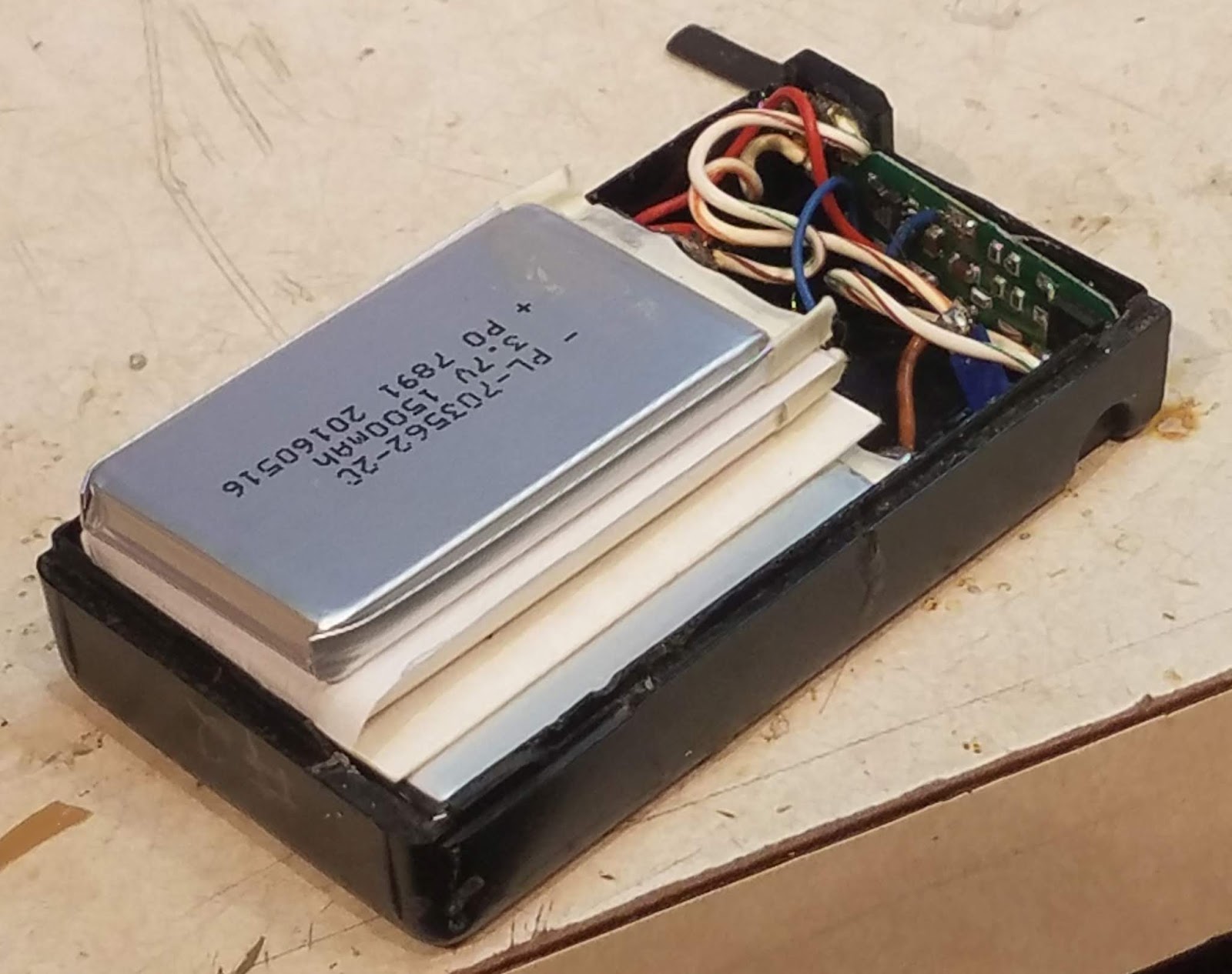 |
| Figure 3: The four cells installed within the case. 2 mil Nomex sheets have been placed between the two parallel cells with a 20 mil Nomex sheet between the two series sets of cells. The pairs of cells are "staggered" to better-allow for the expected expansion of foil-pouch cells such as these. The protection circuit may be seen in the upper-right corner of the pack. Click on the image for a larger version. |
 |
| Figure 4: The completed, rebuilt LiIon battery pack, held together with some polyimide tape - which I had on-hand. Click on the image for a larger version. |
Clear RTV (silicone) sealant/adhesive is used to hold everything together: A thin layer is used between the two parallel cells to hold the Nomex sheet in place - and to hold the two cells together and more RTV is used to hold the two sets of cells at an offset. The use of RTV is suggested as it is flexible and has some "give" - something that is absolutely necessary with these types of cells to avoid damage during their normal use and lifetime.
Charging:
One cannot use the original NiCd or NiMH charger for the "new" battery - instead, a constant-voltage, current-limited supply is used. While this sounds complicated, I simply used an LM317 adjustable voltage regulator - the circuit being taken from the standard data sheet - depicted below in Figure 6 - with the exception that a 5k, 10-turn potentiometer is used to set the voltage, and there is an LED (with series resistor) placed across the output as an indication of applied voltage.
To charge, the regulated supply is set (nominally) to 8.2 volts and allowed to charge for 6-8 hours when powered from a 1-2 amp power supply, after which time the battery should be removed from the voltage source: In the interest of longevity one should NOT apply charging voltage continuously as maintaining a battery at "full charge voltage" accelerates chemical degradation of any lithium-based rechargeable cell. The precise amount of time to leave the battery "on charge" isn't critical: It should be long enough to adequately charge the battery, but it should not be ignored and simply left for long periods.
It is certainly possible to find a cast-off or surplus "8.4 volt" LiIon charger intended for two cells in series and this device could be adapted. The caveat to this is that this charger must have been designed for a "protected" battery pack - the clue to this being that the charger will have exactly two connections to the pack to be charged. Of course, it will be up to you to come up with a way to make a connection to the original battery pack - perhaps in a manner similar to that depicted in Figure 5, below.
Making LiIon cells last longer:|
 |
| Figure 5: Homebrew charger for the LiIon pack. In the lower left is a connector, made from circuit board material and hobby brass, that slides over the top of the battery pack to make contact. The circuit itself (upper right) is built onto a heat sink and contains an LM-317 voltage regulator circuit, an LED, and a 5k, 10 turn potentiometer to set the voltage. The LED, connected on the output side of the regulator, illuminates when voltage comes from the battery (e.g. to make sure that a connection is made to a charger) or the 12 volt (nominal) power source for charging. Click on the image for a larger version. |
To further-promote longevity of the battery it has been suggested by battery manufacturers and other "experts" 1 - footnote that the charge voltage be reduced from the nominal 4.2 volt/cell value - a value of 4.05 volts/cell (or 8.1 volts charging) to double the lifetime (in terms of charge cycles) and slow the inevitable degradation over time: This is likely one of the reasons why I got about 10 years out of the original set when a typical LiIon cell/battery will last about 5 years.
What about capacity loss from not "fully charging" the battery? Charging to 4.05 volts/cell will yield about 80-85% of capacity as compared to a full charge of a new cell, but it is not uncommon for a new LiIon cell - charged consistently to the "full" 4.2 volts/cell - to lose 15-20% after the first year due to degradation. What this means is that in the long run, the net loss is mitigated, anyway, also offset by the slower degradation of the cell over time by this same reduction in charging voltage.
Actual use:
 |
| Figure 6: Circuit diagram of the LiIon charger - just a "datasheet standard" circuit to regulate to the desired charge voltage. The LED may be any color and is used to detect when the battery is properly connected to the charger and to indicate the presence of charge voltage. U1, the LM317, should be mounted to a heat sink. Potentiometer R1 is adjusted to set the output to the desired full-charge voltage. Click on the image for a larger version. |
Having used LiIon cells with my FT-530 for about 20 years now I would not go back to the NiCd/NiMH types again - except, perhaps, unless they were put in the 10-cell AA battery pack shell that I also have. For many years my FT-530 has been programmed to turn itself on (using its built-in clock) in the morning to monitor a local repeater - and it will turn itself off after 30 minutes unless I hit a button or transmit: If I only listen, the radio will go 2-3 months between charges when used this way.
In "heavy" use - such as a public service event where frequent transmission is required - I can use the radio at least "all day" at full power (2-2.5 watts output) without running it down. When the cells are depleted, I get reasonable warning - particularly since the FT-530 has an on-screen voltmeter than may be enabled.
If I see the battery voltage drop below 6.9-7.0 volts during receive I know that I should consider finding the spare pack - and the radio will continue to work until the point at which the display starts to flash at about 5.5 volts. Interestingly, the radio will quit (turn itself off) before the "protection circuit" kicks in due to low cell voltage - but little actual battery capacity is left anyway below 6.0 volts, so it appears that a "2S" (e.g. two series-wired) Lithium-Ion cells are a pretty good match for the FT-530.
Comment: The FT-530 is capable of operating from up to 15 volts, so a "3S" (3 cell in series) pack is possible - but the limited space in this battery pack case means that, at least with these types of cells, that six of these cells cannot be put in series-parallel: Three of these cells in series would yield a "10.8 volt" 1500 mAH pack rather than the nominal "7.2 volts" at 3000 mAH of the pack described here.
Use of LiIon Packs with other, older radios.
Until, perhaps, the early 2000s, many amateur handheld transceivers were shipped with NiCd or NiMH battery packs - and this shows that with proper care and attention to detail that it should be possible to retrofit one of these battery packs with modern LiIon cells, giving the original radio - which is still likely to be very usable these days - much more operational capacity out in the field.
Before "converting" such a radio, there are several things to consider:
- The voltage range of the radio. Keeping in mind that the voltage of a LiIon cell can vary from 4.2 volts, freshly off the charger, down about 3.0 volts meaning that a hypothetical 2-cell battery such as this can produce between 8.4 and 6.0 volts, spending most of its operating time in the 6.8-7.2 volt range. If, in this 2-cell example, your radio can happily operate in this voltage range, your radio might be a good candidate.
- Other examples:
- 3 cells: 9.0-12.6 volts, spending most of its time in the 10.2-10.8 volt range. May be usable for radios that are capable of operating directly from a 12 volt supply.
- 4 cells: 12.0-16.4 volts, spending most of its time in the 13.6-14.4 volt range. Many "12 volt" capable radios have an upper voltage limit of 15.0 volts, so this may be too high for safe operation with a freshly-charged battery.
- A means of charging. Make sure that you can charge any battery that you might put together. In my case, I built a very simple charger (see figures 5 and 6) but I could have adapted an old LiIon charger - or even used a bench-top power supply that was properly adjusted for the charge voltage. If your radio has some means of built-in charging, it probably cannot be safely used.
- A usable battery pack case. In many instances one can re-use the original battery pack's case and stuff into it appropriately-sized cells as was done here. If one does this it will be necessary to carefully measure the internal dimensions and find the prismatic cells that will fit inside - remembering to allow room for the "protection circuit".
* * * * * *
Footnote:
1 - "How to Prolong Lithium-Based batteries" - https://batteryuniversity.com/learn/article/how_to_prolong_lithium_based_batteries
This page stolen from ka7oei.blogspot.com
[End]