|
Figure 1:
The completed Temperature/Humidity/Line Voltage web
server/telemetering device. The remote temperature/humidity
sensor is the unit to the left. The two AC-DC wall adapters used for
powering the unit and monitoring mains voltage are not visible.
Click on the image for a larger version. |
As anyone who reads this blog probably knows, I have a bit to do with the operation and maintenance of the
Northern Utah WebSDR - a remote receiver system that allows anyone with Internet access and a web browser to listen to the LF, MF, HF and some of the VHF bands as heard from a rural site in Northern Utah. The equipment for this receiver system is located a small building in the middle of mosquito and deer-fly infested range land near brackish marshes - no-where that anyone in their right mind would like to be during most of the year. With the normal weather in the summer and many clear days, this building gets
hot at times: It's been observed to exceed 130F
(55C) on the hottest days inside - a temperature that causes the fans on the computers scream!
Even though electronic equipment is best kept at
much lower temperatures, this isn't practical in this building as it would be prohibitively expensive to run the on-site air conditioner full time - but all we really need to do is to keep the building closer to the outside temperature and even though it may be uncomfortable for humans, it is enough to keep the electronics happy. To that end, vents have recently been installed to allow convection to pull away most of the heat and the exterior will soon been painted with white "RV" paint to
(hopefully) reduce the heating effects of direct sun.
It would make sense, then, that we had a way to remotely monitor the building's internal temperature as a means of monitoring the situation. Additionally, temperature information can also be used to make minor adjustments to the frequencies of some of the receivers' local oscillators to help counter thermal drift.
 |
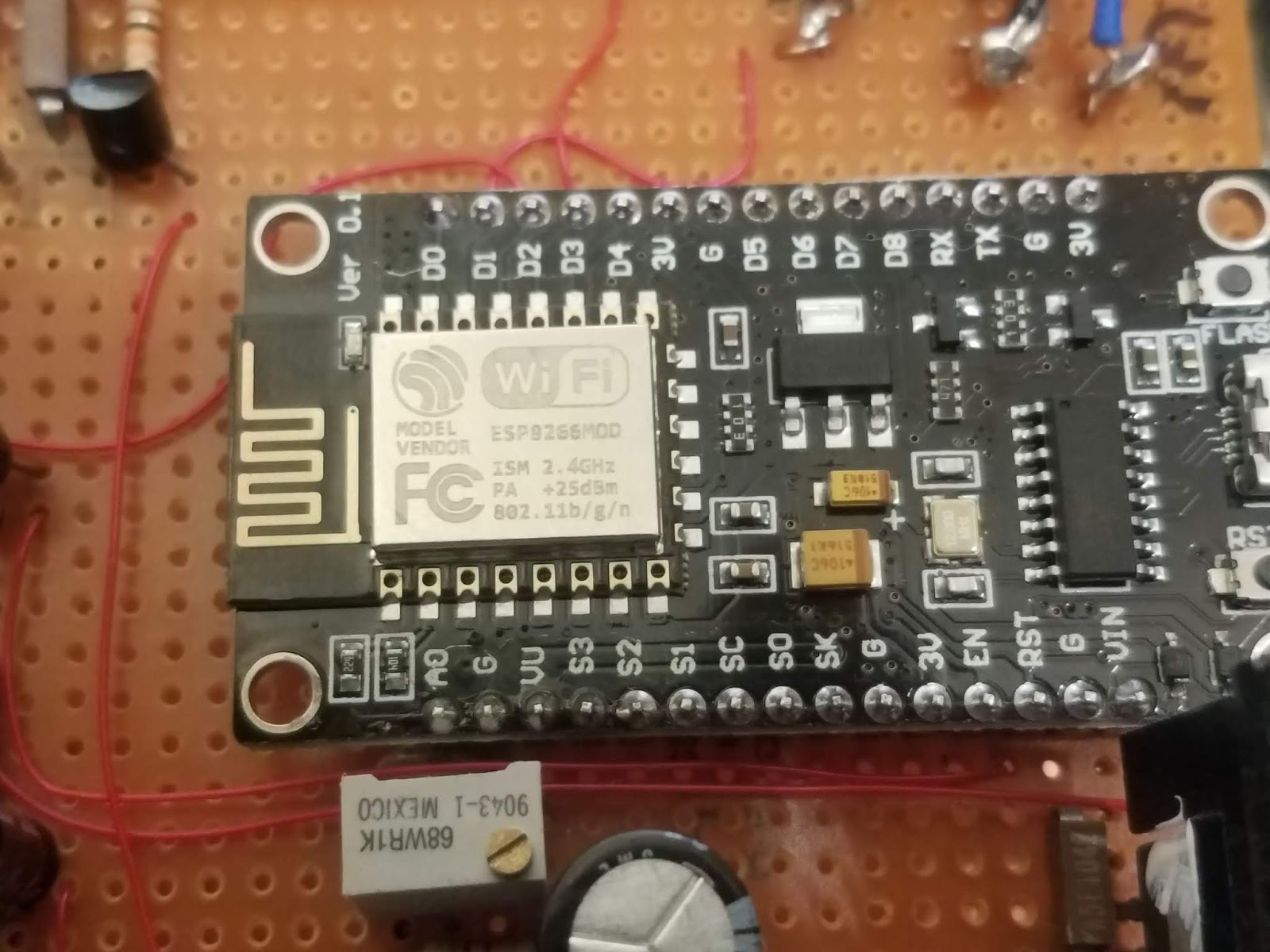
Figure 2:
The "business end" of the small board that contains the
ESP8266 module - the device with the metal shield.
This board also includes a USB plug, a CH340-like
USB to serial converter that allows for programming
and debugging and a voltage regulator that allows direct
operation of this board from a 5 volt supply.
As can be seen here and in Figure 4, the ESP8266 board was,
itself, mounted to a larger prototyping board for construction
of the ancillary circuitry.
Click on the image for a larger version. |
On site we
do have an Ambient Weather
(tm) station, but anyone who has used this
(or similar) hardware knows that some vendors of this type of gear make it difficult to obtain your own data without jumping through hoops: Although this data is visually available on the local display or even on a web site, it is a bit awkward to pull this data from their system and
(at least with the newer versions of the hardware) one cannot get this data locally from the weather station itself.
Fortunately, the most-needed data - temperature inside the building - is easily measured using inexpensive sensors, so it made sense to throw together a device that could make these measurements and present them in an easy-to-use web interface.
The ESP8266 "Arduino" board:
As is often the case with projects like this, the Internet has the answer. The ESP8266 is an inexpensive embedded computer module that has a reasonable amount of program memory and RAM and it also sports hardware such as a WiFi module, several digital I/O pins and a 10 bit A/D converter. What this means is that for less than U.S.$12 you can get
two of these delivered to your doorstep that contain an already-mounted ESP8266 module on a carrier board with a USB port in a format that strongly resembles that of the ubiquitous Arduino development board. More importantly, the Arduino IDE supports this board meaning that it is pretty easy to use this hardware in your own projects.
Because the '8266 board has been available for quite a while, there is a large library of software for it - including a small web server and code to interface with many types of devices, including the well-known
(and relatively inexpensive) DHT-22 temperature and humidity sensor.
Comment: The ESP8266 variant used here appears to be the "12E" version which has 32 Mbit
(4 Mbytes) of Flash memory and "around 50k" of RAM.
The "DHT Humidity and Temperature web server":
It took only a few minutes to find online several implementations of a web server coupled with the DHT-22 sensor - and I chose what seemed to be a popular version on a web site by Rui Santos - to look at it yourself, go here:
randomnerdtutorials.com/esp8266-dht11dht22-temperature-and-humidity-web-server-with-arduino-ide/
Presented in good detail, it was only about 20 minutes from the start to tack a few flying leads to my $6 ESP8266 "Arduino" board to connect the DHT-22 sensor before I had a wireless web server on my workbench that was happily reading the temperature and humidity.
Of course, getting something working can be miles from a finished project and that was certainly the case here as the project was about to be subject to self-inflicted feature creep and code bloat as I'd already decided that I wanted it to do two
other things as well:
- Monitor the AC line voltage. The WebSDR receive site - being rural - suffers from very dirty AC mains power. We have seen the nominal 120 volt mains exceed 140 volts for brief periods in addition to the frequent outages - and it would be nice to have a device that would allow us to record such excursions.
- Telemeter the gathered information via RF. Because the ESP8266 is a small computer - and it has data that we want - and we are at a radio receive site - it would be a simple matter to have this unit tap out the information using Morse code on a low-power, unlicensed (part 15) transmitter that was capable of being received by the on-site receivers.
The final result is this, in schematic form:
 |
Figure 3:
The schematic of the support circuitry of the ESP8266 unit described, including a pictorial representation of the processor board itself.
Click on the image for a larger version. |
Circuit description:
The ESP8266 is treated as a single component - the support circuit being connected to the pins as noted with the '8266 itself being mounted on a larger board as can be seen in Figure 4, below. It's worth noting that this is a 3.3 volt device which means that the "high" output voltage is around 3 volts: If I'd needed a digital input, I would have had to make sure that the logic high input level was appropriately limited in voltage.
Power supply and monitoring:
There are two uneregulated AC-DC transformer "wall warts", both being a low-voltage transformer (9-12 volts AC) with full-wave rectification and capacitive filtering - one to power the unit and the other to monitor the line voltage. The separation of these two function is necessary for obvious reasons: We'd want the unit to continue to function when the AC mains was out, but continue to run from the UPS which means that we can't monitor or own power supply! Even if we could, the current consumption of the unit varies a bit and as a consequence, so does the unregulated voltage from the monitor supply. The source of power for the unit itself could be anything that can provide 10-15 volts DC - regulated or not - but these AC->DC transformers were on-hand, plus being simple transformer-rectifier-filter units, they do not generate RF noise - unlike some switching-type devices - a factor important at a radio receive site.
The power from each of the AC-DC adapters enter via a screw terminal strip and immediately passes
through a pair of bifilar-wound inductors - the purpose here being to
provide RF isolation: Because this device contains a computer and a
low-power transmitter, we don't want any signals on this device from
being radiated on the power leads.
The first AC-DC adapter is used to power the unit - a red LED indicating that voltage is present. Following this is a "bog standard" 5 volt regulator using a 7805 to provide a lower voltage to feed to the "VIN" pin of the ESP8266 board and to run other circuitry on board.
The other wall wart has only a light load - most of the current being consumed by D4, an orange LED used to indicate that the mains voltage being monitored is present. As you would expect, an unregulated AC-DC supply like this isn't a precision instrument when it comes to measuring line voltage as it is not any sort of RMS measuring device and with its built-in filter capacitor, it's also relatively slow to respond - but it is "good enough" for the task at hand.
This voltage is divided down via R3 and variable resistor R4 for the 0-3.3 volt input range of the "A0"
(analog input) pin on the ESP8266 module.
(Note: It's reported that A/D range of the "raw" '8266 module is 0-1 volt - apparently this board includes a voltage divider to scale from 3.3 volts.) Resistor R4 is 10 turn unit used for calibration of the line voltage.
Watchdog timer:
 |
Figure 4:
The completed ESP8266-based temperature, humidity and line voltage
monitoring device. The CW transmitter portion is in the upper-left corner
of the board with the 555-based watchdog timer below it. In the lower-
right corner is the 7805 regulator with its heat sink with R4, the
calibration for the line voltage being seen just below the lower-left
corner of the ESP8266 board. The gray wire at the top connects to the
small board containing the DHT-22 temperature/humidity sensor.
The entire unit is mounted via stand-offs into the lid of the plastic case
depicted in Figure 1. Inside the lid I placed a sheet of self-adhesive
copper foil that is used as a ground plane to which the input filter
capacitors (C1, C3), the LEDs and the ground connections of the
board are soldered.
Click on the image for a larger version. |
Because this device is unattended in a remote location I took the precaution of adding a simple hardware watchdog timer. The software generates a pulse train
(nominally a square wave) on pin "D2" which is then applied to transistor Q1: Capacitive coupling, via C7, is used as a DC coupled signal would have made it possible that a watchdog reset condition could have been simulated if the pin were stuck "high". The timer itself is the ubiquitous NE555 "programmed" via C8 and R7/R8 to have an approximately 45 second period.
The pulse train from pin D2 pulses Q1, keeping timing capacitor C8 discharged - but if the pulse train stops, pin 3 will go high after the timing period, briefly pulsing the "RST"
(reset) pin of the EP8266 via capacitively-coupled Q2. A 45 second period was chosen as it takes about 8 seconds for the ESP8266 to "boot up" enough for the software to generate the - and it also allows just enough time to upload the program.
During initial development one would probably
not plug a 555 into its IC socket as spurious resets would likely be an annoyance as there may not be code to create the reset pulses, but with the size of the code for this project the reset period is long enough to allow uploading of the code before a reset occurs and the pulses resume.
Temperature/Humidity sensor:
The readily-available DHT-22 sensor is used, chosen over the slightly cheaper DHT-11 as the '22 offers a wider temperature and humidity measurement range - although the software can be configured to work with either one. To avoid erroneous temperature or humidity measurements from the unit's heat generation, this sensor is mounted on its own board as depicted in Figure 3. On this small board is not only a power supply bypass capacitor (C20) but also a pull-up resistor R19.
The "sensor module" - visible in Figure 1 - was placed inside a small piece of ABS tubing
(gray non-metallic electrical conduit) for protection with small pieces of nylon window screen glued to each end to keep out insects, but allow air flow to permit accurate measurements.
CW transmitter:
Because it is a computer - and there was plenty of code space - I decided to add Morse Code generation to provide telemetry that could be picked up by the HF receivers on site. Stealing my own Morse-generating C code from a 20+ year old PIC project, I made minor modifications to it, using a hardware-derived timer in the main loop to provide a sending clock. The Morse generating code toggles D3, setting it high to "key" the transmitter.
The signal from pin D3 goes to Q3 which is wired via current-limiting resistor R13 to Q4, a PNP transistor to provide "high side" keying of the unregulated V+ supply. This voltage is then passed through resistor R14 which provides both a bit of current limiting and, with C12, some R/C filtering to slow the rise/fall of the voltage: Without it the RF would have been keyed very "hard" causing objectionable "key clicks" on the rise and fall of the RF waveform. This voltage is used to key both the buffer and the output amplifiers, described below.
The signal source is a 28.57 MHz crystal "can" oscillator module that I found in my junk box. While I could, in theory, have done CW keying by turning this oscillator on and off, these oscillators aren't designed to be particularly stable and doing so would have caused the oscillator to "chirp" - that is, the short-term frequency drift that occurred when power was applied would have caused an objectionable shift in the received audio tone during keying.
Instead, the oscillator was powered continuously with its output fed to Q5, an emitter-follower buffer: R15 "decouples" the oscillator from Q5 somewhat and without it, the RF current into the base of Q5 would increase when its collector voltage was switched off causing the oscillator to heat internally, resulting in a frequency shift. The output of the buffer circuit is then passed via resistive and capacitive coupling to Q6 which is used as the final RF amplifier. L1 is used to decouple its collector from the power supply while C16 removes the DC voltage from the RF output. The remaining components - C17-C19 and L2/L3 comprise a low-pass filter resulting in harmonics that are at least 40dB below the fundamental.
This circuit was originally built without Q5, the buffer amplifier, but I had two issues that could only be resolved by its addition:
- Backwave. Because the oscillator runs continuously, there will inevitably be a bit of leakage - and in CW where it is the very presence and absence of the signal that is used to convey the information, having a rather strong signal when there is supposed to be silence made it difficult to "copy" the code. When Q6 was turned off, there was enough leakage between its base and collector to offer only about 15 dB of attenuation when the transmitter was "un keyed".
- Oscillator stability. As noted above, R15 was used on Q5 to limit the current out of the oscillator to prevent frequency drift as buffer transistor Q5 was keyed. When I'd tried to drive the output (Q6) directly - without a buffer - I had the same problem: If I coupled enough energy to drive the transistor, the frequency would vary with the CW keying - and the backwave would get worse - but if I increased the resistor enough to reduce the problem, the transistor would be properly driven - which also increased the backwave as the transistor's output would fall in comparison to the signal leakage.
With the circuit built as shown the backwave is at least 40dB below the keyed output - which is more than adequate for the task.
The code:
As noted above, the basis of the project was that published by Rui Santos - and in the spirit of open source, the code was modified:
- The original code included some small graphics served on the web page - but in line with the KISS principle, this was stripped out in favor of the simplest text, using only standard HTML formatting.
- Additional code was added to read the AC mains voltage via pin "A0". In the main "loop" routine, this input is read 100 times a second and then averaged, with a new reading made available every second. This average removes most of the noise on the pin - some of which is internal to the '8266 itself, but the majority of which is due to a small amount of AC ripple on the voltage monitoring line.
- Additional code was added to record the minimum and maximum of all of the monitor parameters - that is, temperature, humidity and line voltage.
- The default of the code was to read the temperature in Celsius, but being in the U.S. I added code to give the readings in Fahrenheit as well.
- The web server code was modified to display all of the available data - the temperature in Fahrenheit and Celsius, the humidity and line voltage - and their minimum and maximum values.
- Addition modification was made to the web server code to allow each of the data points to be read in simple text format to simplify parsing for remote monitoring and logging of this data. The nature of the the web server actually made it very easy!
- Yet another modification was made to reset the minimum and maximum readings and to provide information as to how many seconds it had been since a reset had occurred. The temperature/humidity min/max reset is separate from the line voltage min/max.
- The code also keeps track of mains voltage that falls below a threshold (an outage) or exceeds a threshold (a "surge") - both of which are extremely common at the remote receive site.
- I added my own Morse generation code, ported from some PIC-based "C" code that I wrote about 25 years ago and interfaced it with the main timing loop.
Source Code:
If you are interested in the source code (sketch) you may find it at THIS LINK.
A few minor changes/improvements - noted in the source code's header - have been made since the original posting.
Implementation:
 |
Figure 5:
A screen shot of the web page. This same information is available
from individual links (on the bottom half of the page) that will
return just the information requested, making it trivial to obtain
individual data points using something like WGET.
Click on the image for a larger version. |
As mentioned, with the WiFi capability of the ESP8266, the information that this device records is available via a web page on the wireless network: One only need enter the SSID and wireless password at compile time. For reasons obvious to anyone familiar with the Internet, this device won't be accessible from the web itself, but only to devices on the local network.
With the CW generator operating on 28.57 MHz, this signal lands within the 10 meter amateur band - and with this device being co-sited with receivers, it is a simple matter of tuning to that frequency to hear the telemetry. Even though the RF output power is on the order of 50 milliwatts, the actual transmit "antenna" is a very small piece of wire - large enough to radiate just enough signal to be heard via the nearby antennas but not nearly enough to exceed FCC part 15 rules, eliminating the need for this device to transmit an FCC-issued callsign.
Comment:
This device was installed at the Northern Utah WebSDR shortly after this article was originally posted. You may hear the Morse portion of this device via this link.
This page stolen from ka7oei.blogspot.com
[END]