Showing posts with label FSO communications. Show all posts

Wednesday, April 19, 2017

A daylight-tolerant TIA (TransImpedance Amplifier) optical receiver

While the majority of my past experiments with through-the-air free-space optical (FSO) communications were done at night, for obvious reasons, I had also dabbled in optical communications done during broad daylight, with and without clouds.

The challenge of daylight:

Clearly, the use of the cloak of darkness has tremendous advantages in terms of signal-noise ratio and practically-attainable communications distances, but daylight free-space optical communications has some interesting aspects of its own:
  • It's easier to see what you are doing, since it's daylight!
  • Landmarks are often easier to spot, aiding the aiming.
  • Even in broad daylight, it is possible to provide signaling as an aiming aid, such as a mirror reflecting the sun - assuming that it is sunny.
  • The sun is a tremendous source of thermal noise, causing dilution of the desired signals.
  • Great care must be taken when one wields optics during the day:  Pointing at the sun or a very strong specular reflection - even briefly - can destroy electronics or even set fire to various parts of the lens assembly!
As you might expect the biggest limitation to range is the fact that the sun, with its irradiance of around 1kW/m3 (when sunny) can overwhelm practically any other source:  This is why the earliest "wireless" communications methods often used reflected sunlight, notably the Heliograph, where a mirror was "modulated" with telegraph code, or the "Photophone", a wireless audio transmitter using reflected light, an invention of Alexander Graham Bell from the 1870s with earlier roots - a device that Bell himself considered to be his greatest invention.
Figure 1:
Optical communications during daylight.  In the center of this contrast-enhanced picture (the red spot) is the light from an optical transmitter using a 30+ watt LED at a distance of 13.25 miles (21.3km).  This image is from my own "modulatedlight" web site.
Click on the image for a larger version.

Means of detection:

While the modulated speech may be produced in any number of ways (vibrating mirror, high-power LED, LASER) some thought must be given on the subject of how to detect it.  While the detector itself need not be spectacularly sensitive due to the nearly overwhelming presence of the thermal noise from the sun, it is worth making it "reasonably" sensitive so that this is not the limiting factor.  An example of an un-sensitive optical receiver (e.g. one that is rather "deaf" and itself is not likely to be sensitive enough even for daylight use) is a simple circuit using a phototransistor as depicted below:
Figure 2:
A simple phototransistor-based receiver (top):  Note that there's an error in the diagram in that it shows a photodiode instead of a phototransistor.  This circuit was built by Ron, K7RJ, simply to demonstrate the ability to convey audio a short distance:  It is (intentionally) not optimized in any way and is not at all sensitive!  A similar, but slightly better circuit was found on the Ramsey Electronics LBC6K "Laser Communicator", which was also quite "deaf".  See the article Using Laser Pointers for Free-Space Optical Communications - link that more thoroughly explains this issue.  This image is from my own "modulatedlight.org" web site and used with the permission of Ron Jones, K7RJ.
Click on the image for a larger version.

The circuit in the top half of Figure 2 (above) depicts one of the simplest-possible optical receivers - and one of the "deafer" options out there.  In this case a biased phototransistor is simply fed into an LM386 audio amplifier and the signal is amplified some 200-fold (about 46dB.)  As noted in the caption, this was a "quick and dirty" circuit to prove a concept and was, by no means optimized nor does it take maximum advantage of the potential performance of a detector.

As it turns out a phototransistor isn't really the ideal device because it is, by itself, intrinsically noisy.  Another, more practical issue is that its active area is typically quite small which means that it won't intercept much light on its own.  Of course, any half-hearted attempt to use any device for the detection of optical signals over even a rather short distance of a few hundred meters would include the use of a lens in front of the detector - no matter its type:  The lens will easily increase the "capture area" by many hundred-fold (even for a small lens!) and will effect noiseless amplification with the added benefit of rejecting light sources that are off-axis.  With the tiny active area of a phototransistor it can be difficult to properly and precisely focus the distant light onto that area and it is likely that unless very good precision in both alignment and focus can be maintained, the "spot of light" being focused onto the phototransistor will be larger than its active area, "wasting" some of its light as it "spill"s over the sides.

One of the biggest problems with a circuit like this is that there will be a level of light at which the phototransistor saturates, and when this happens the voltage across its collector and emitter will go very close to zero and the received signals will disappear, possibly "un-saturating" only briefly during those points in the modulation where the source light happens to go toward zero, resulting in badly distorted sound.  In broad daylight the phototransistor may be hopelessly saturated at all times unless an optical attenuator (e.g. neutral density filter) is used to reduce the total light level and/or more current is forced through it.

Introducing the TransImpedance Amplifier (TIA):

A much better circuit is the TransImpedance Amplifier, a simple circuit that proportionally converts current to voltage.  With this circuit (see Figure 3) one would more likely use a PIN Photodiode, a device akin to a solar cell, in which the output current is pretty much proportional to the light hitting its active area. This is quite unlike the manner in which a phototransistor is typically used where in the former case the impinging light causes a voltage drop across the device.

Figure 3:
A simple transimpedance amplifier.
(Image from Wikipedia)
In this circuit the junction between the inverting (-) and noninverting (+) inputs of the op-amp "wants" to be zero, so as the current from the photodiode increases in the presence of light, its output voltage will increase, sending a portion of that current through feedback resistor "Rf" until the overall voltage is zero.  What this means is that the output voltage, Vout, is equal to the current in the photodiode multiplied by the magnitude of resistance, Rf - except that the voltage will be negative, since this is an inverting amplifier.

As an example, assume that Rf is set to 1 Megohm.  Assuming no leakage and a "perfect" op-amp we can determine that if there is -1 volt output, we must have 1/1000000th of an amp (e.g. 1 microamp) attributed to Ip, the photodiode current.  This sort of circuit is often used as a radiometric detector - that is one in which its output is directly proportional to the amount of light striking the photodiode' surface, weighted by intervening optics and filters and the spectral response of the detector itself.

For more about the Transimpedance Amplifier circuit, visit the Wikipedia page on the subject - link.

This is OK when the photodiode is in complete darkness - or in near-complete darkness, but what about strong light?  We can see from the above example that if we have just 10 microamps - a perfectly reasonable value for a typical photodiode such as the BPW34 in dim-to-normal room lighting - that Vout would be -10 volts.  If this same circuit were taken outside, the diode current could well be many hundreds or thousands of times that amount and this would "slam" the output of the op amp against a power supply rail.

A daylight-tolerant TIA:

One of the typical means of counteracting this effect is to capacitively couple the photodiode to the op amp so that only changing currents from a modulated signal get coupled to it, blocking the DC, but there is another circuit that is arguably more effective, depicted in Figure 4, below.

Figure 4:
A "Daylight Tolerant" Transimpedance amplifier circuit.
In this circuit the DC from the output is fed back to "servo" the photodiode's "cold" side so that its "hot" side (that connected to the op amp's inverting input) is always maintained at the same potential as the noninverting input, eliminating the DC offset caused by ambient light.  The disadvantage of this method is that it does not lend itself well to reverse-biasing the photodiode to reduce its capacitance, but between the high intrinsic thermal noise levels of daylight and the related photoconductive shunting of the device due to high ambient light, this is largely unimportant.  For the photodiode the common and inexpensive BPW34 may be used along with many other similar devices.
Click on the image for a larger version.

This circuit is, at its base, the same as that depicted in Figure 3, with a few key differences:
  • An "artificial ground" is established using R101 and R102, allowing the use of a single-polarity power supply.  This artificial ground is coupled to the actual ground via C102 and C103 making it low impedance to all but DC and very low AC frequencies.
  • The voltage output from the transimpedance amplifier section (U101a) is feed back via R104 to the "ground" side of the photodiode (D101) to change its "ground".  If there is a high level of ambient light, the voltage at the "bottom" end of D101 (at D101/C107) goes negative with respect to the artificial ground, setting the DC voltage at the non-inverting input of the op amp to zero, cancelling it out.
  • R104 and C106 form a low-pass filter that passes the DC offset voltage to the bottom of D101, but blocks the audio.  In this way the DC resulting from ambient light that would "slam" the op amp's output to the negative rail is cancelled out, but the AC (audio) signals remain.  The time constant of this R/C network is slow enough to be "invisible" all but the very lowest (subaudible) frequencies, but more than fast enough to track changes in ambient light.
  • By not placing any additional components between the "hot" end of the photodiode and the op amp, the introduction of additional noise from the components (including microphonic responses of the coupling capacitor) is greatly reduced.
In the above circuit the values of R103 and C104 would be chosen for the specific application.  In a circuit that is to be used at very high light levels where high sensitivity is not very important a typical value of R103 would be 100k to 1 Megohm:  Do not use a carbon composition but a carbon film or (better yet) metal film resistor is preferred for reasons of noise contribution.  While tempting to use, a variable resistor at R103 is also not recommended as these can be a significant source of noise.  If multiple gain ranges are used, small DIP switches, push-on jumpers or even high-quality relays - wired to the circuit - could be used to select different feedback resistances, knowing that these devices have the potential of introducing noise as well as additional stray circuit capacitance.  (Such a relay/switch would be wired on the "output" side of the op amp/relay of the feedback resistance(s) and proper component selection, layout and appropriate shielding would need to be considered.)

C104 is used to compensate for photodiode and other circuit capacitance and without it the high frequency components would rise up (e.g. "peak"), possibly resulting in oscillation and general instability.  Typical values for C104 when using a small-ish photodiode like the BPW34 are 2-10pF:  Using too much capacitance will result in unnecessarily rolling off high frequency components, but will not otherwise cause any problems.  A small trimmer capacitor may be used for C104, either "dialed in" for the desired response and left in permanently or optimally adjusted, measured, and then replaced with an equal-value fixed unit.

Again, the reason why the ultimate in high sensitivity is not required on a "Daylight Tolerant" circuit is that during the daytime, the dominant signal will be due to thermal noise from the sun - a signal source strong enough that it will submerge weak signals, anyway:  It need be sensitive enough only to be able to detect the sun noise during daylight hours.

The op amp noted in Figure 4 is the venerable LM833, a reasonably low-noise amplifier and one that is cheap and readily available (and actually works well down to 7 volts - a bit below its "official" voltage rating allowing the above circuit to powered from a single 9 volt battery) but practically any decent low-noise op amp could be used:  Somewhat better performance may be obtained using special, low-noise op amps, but these would be "overkill" under daylight conditions.

For nighttime use - where better sensitivity was important - a standard "TIA" amplifier that omits the DC feedback loop to cancel out the DC (potentially noise-contributing) components along with higher values of Rf would offer better performance, but for much better low-noise performance (e.g. 10-20dB better ultimate sensitivity) under low-light conditions than is possible with standard components at audio frequencies in a TIA configuration the "Version 3" optical receiver circuit described on the page "Gate Current in a JFET..." - link is recommended, instead.


Additional web pages on related topics:
The above web pages also contain links to other, related pages on similar subjects.


[End]

This page stolen from "ka7oei.blogspot.com".

Monday, April 18, 2016

Combatting scintillation effects on optical voice links

One interesting aspect of the amateur radio hobby that is rarely discussed is the use of the "Above 275 GHz" bands.  While one might, at first, think that this might require some exotic "componentry" to use these wavelengths, to assume such would ignore the fact that this includes "optical" frequencies - which is to say, visible light.

Working with visible light has a tremendous advantage over other "frequencies" in that we have some built-in test equipment:  Our eyes.  While generally uncalibrated in terms of "frequency" and power (e.g. brightness) they are of great help in building, setting up and troubleshooting such equipment.

For years now lasers have been considered to be the primary source of optical transmitters - which makes sense for some of the following reasons:
  • Lasers are cool!
  • They may be easily modulated.
  • Lasers are cool!
  • "Out of the box" they produce nicely collimated beams.
  • Lasers are cool!
  • Low-power diode-based lasers are inexpensive and easy to use.
  • Lasers are cool!
While lasers are (almost) exclusively used for all types of fiber-optic based communications, one might ask oneself if they are equally useful/effective when the medium is the atmosphere rather than a stable, glass conduit?

The answer is:  It depends.

If one is going very short distances - perhaps up to a few hundred meters - the atmosphere can be largely ignored unless there is something that is causing severe attenuation of the signals (e.g. rain, snow or fog) but as the distances increase - even if there is not some sort of adverse condition causing such loss - there are typically nonuniformities in the atmosphere caused by thermal discontinuities, wind, atmospheric particulates, etc. that causes additional disruption.

The fact that Lasers produce (generally) coherent beams in terms of frequency and phase - gas lasers usually more so than most semiconductor types - actually works against efforts in making a long-distance, viable communications link because the atmosphere causes phase disruptions along the path length resulting in rapid changes in amplitude due to both constructive and destructive interference of the wavefront.

In the past decade or so, high-power LEDs have become available with significant optical flux.  Unlike Lasers, LEDs do not produce a coherent wavefront and because of this they are generally less affected by such atmospheric phenomenon, as the video below demonstrates:

Figure 1:
Visual example of laser versus LED "lightbeam"
communications.

Admittedly, the example depicted in Figure 1 is somewhat unfair:  The transmit aperture of the laser used for this test was very small, a cross-sectional area of, perhaps, 3-10 square millimeters, while the aperture of the LED optical transmitter was on the order of 500 square centimeters.  Even if both light sources were of equal quality and type (e.g. both laser or both LED) that using the smaller-sized aperture would be at a disadvantage due to the lack of "aperture averaging" - that is, more subject to scintillation due to the small, angular size of the beam causing what is sometimes referred to as "local coherence" where even white light can, for brief, random intervals, take on the interference properties of coherent light:  It is this phenomenon that causes stars to twinkle - even briefly change color - while astronomical objects of larger apparent size such as planets usually do not twinkle.

Figure 2:
Adapter used for emission of laser light via the telescope.
Contained within is a laser diode modified to produce
a broad, fan pattern to illuminate the mirror of the
telescope.

For an interesting article on the subject of scintillation, see "The Sizes of Stars" by Calvert - LINK.

Based on this one might conclude that the larger the aperture for emitting will reduce the likelihood that the overall beam will be disrupted by atmospheric effects - and one would be correct.  The use of a large-area aperture tends to reduce the degree of "local coherence" described in the Calvert article (linked above) while also providing a degree of "aperture averaging".  As an aside, this effect is also useful for receiving as well as can be empirically demonstrated by comparing the amount of star twinkle between the naked and aided eye:  Binoculars are usually large enough to observe this effect.

For a fairer comparison with more equal aperture sizes the above test was re-done using an 8 inch (approx. 20cm) reflector telescope that would be used to emit both laser and LED light.  To accomplish this I constructed two light emitters to be compatible with a standard 1-1/4 inch eyepiece mount - one using a 3-watt red LED and another device (depicted in Figure 2) using a laser diode module that was modified to produce a "fan" beam to illuminate the bulk of the mirror.

Both light sources were modulated using the same PWM optical modulator described in the article "A Pulse Width Modulator for High Power LEDs" - link - a device that has built-in tone generation capabilities.  Since the same PWM circuit was used for both emitters the modulation depth (nearly 100%) was guaranteed to be the same.

To "set up" this link, a full-duplex optical communications link was first established using Fresnel lens-based optical transceivers using LEDs and the optical receiver described in the article "A Highly Sensitive Optical Receiver Optimized for Speech Bandwidth" - link.  With the optical transmitters and receivers at both ends in alignment, the telescope was used as an optical telescope to train it on the far end, using the bright LED of the distant transmitter as a reference.  With the telescope approximately aligned, the LED emitter was then substituted for the eyepiece and approximately refocused to the effective optical plane of the LED.  Modulating the LED with a 1 kHz tone, this was used with an "audible signal level meter" that transmitted a tone back to me, the pitch of this tone being logarithmically proportional to the signal level permitting careful and precise adjustment of both focus and pointing.

For an article that describes, in detail, the pointing and setting-up of an optical audio link, refer to to "Using Laser Pointers For Free-Space Optical Communications: - LINK.

Substituting the laser diode module for the LED emitter the same steps were repeated, the results indicating that the two produced "approximately" equal signal levels (e.g. optical flux at the "receive" end.)  Already we could tell, by ear, that the audio conveyed by the laser sounded much "rougher" as the audio clip in Figure 3, below, depicts.

Figure 3:
Audio example of laser versus LED "lightbeam"
communications over a 15 mile (24km) free-
space optical path.
Music:  "Children" by Robert Miles, used in
accordance with U.S. Fair Use laws.

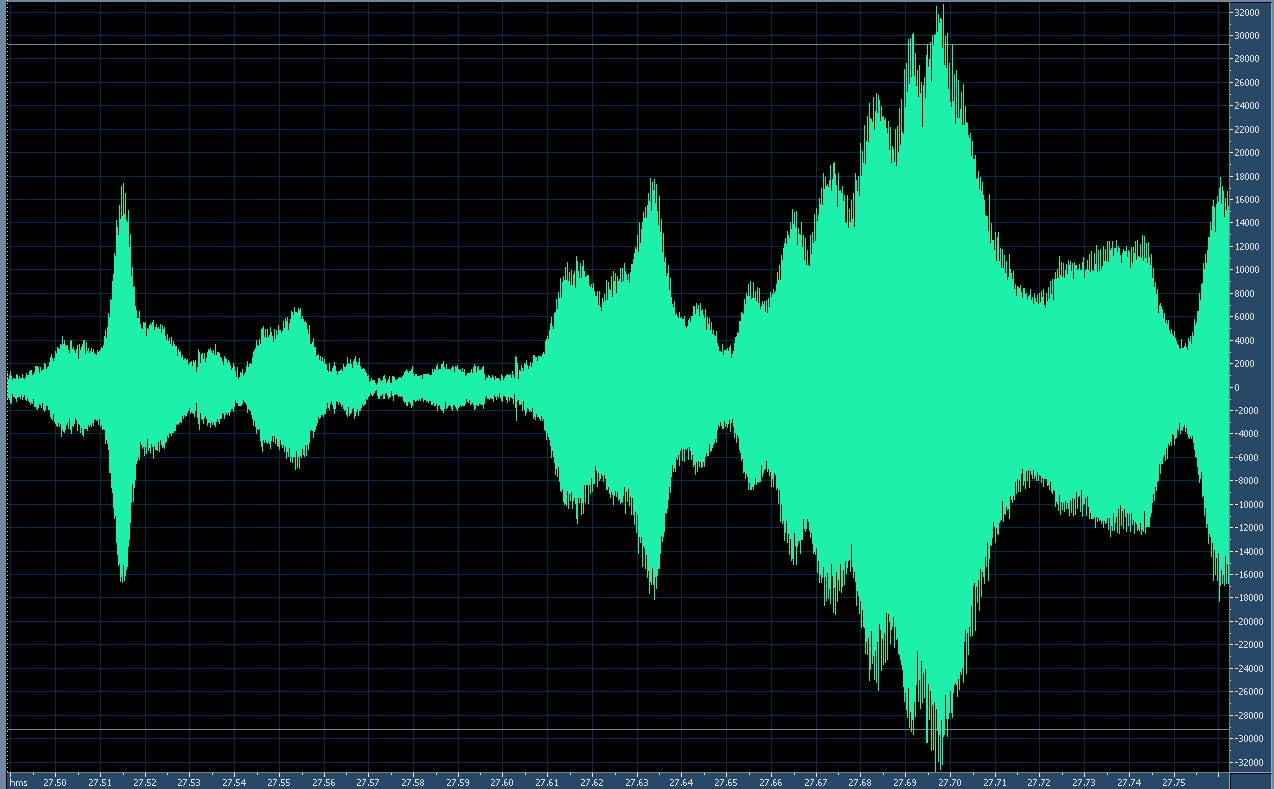
Figures 4 and 5, below, depict the rapid amplitude variations using a transmitted 4 kHz tone as an amplitude reference over a "Free Space Optical" path of approximately 15 miles (24km).  The horizontal axis is time and the vertical axis is linear amplitude.

Note the difference in horizontal time scales between the depictions, below:

Figure 4:
Scintillation of the laser-transmitted audio (4 kHz tone).
The time span of this particular graph is just over 250 milliseconds (1/4 second)
Click on the image for a larger version.


Figure 5:
Scintillation on the LED-transmitted audio (4 kHz tone).
In contrast to the image in Figure 4, the time span of this amplitude representation is nearly 10 times
greater - that is, approximately 2 seconds.  The rate and amplitude of the scintillation-caused
fading are dramatically reduced.
Click on the image for a larger version.

Laser scintillation:

As can be seen from Figure 4 there is significant scintillation that occurs at a very rapid rate.  The reference of this image is, like the others, based on a full-scale 16 bit sample.  Analysis of the original audio file reveals several things:
  • While the "primary" period of scintillation is approximately 10 milliseconds (100Hz) but there is evidence that there are harmonics of this rate to at least 2.5 milliseconds (400 Hz) - but the limited temporal resolution of the test tone makes it difficult to resolve these faster rates.
  • Other strong scintillatory periods evident in the audio sample occur at approximate subharmonics of the "primary" scintillatory rate, such as 75 and 150 milliseconds.
  • The rate-of-change of amplitude during the scintillation is quite rapid:  Amplitude changes of over 30 dB (a factor of 1000) can occur in just 20 milliseconds.
  • The overall depth of scintillation was noted to be over 40dB (a factor of 10000) with frequent excursions to this lower amplitude.  It was noted that this depth measurement was noise-limited owing to the finite signal-noise ratio of the received signal.
LED scintillation:

Figure 5 shows a typical example of scintillation from the LED using the same size emitter aperture as the laser.  Analysis of the original audio file shows several things:
  • The 10 millisecond "primary" scintillatory period observed in the Laser signal is pretty much nonexistent while the 20 millisecond subharmonic is just noticeable.
  • 150 and 300 millisecond periods seems to be dominant, with strong evidence of other periods in the 500 and 1000 millisecond range.
  • The rate-of-change of amplitude is far slower:  Changes of more than 10 dB (a factor of 10) did not usually occur over a shorter period than about 60 milliseconds.
  • The overall depth of scintillation was noted to be about 25 dB (a factor of about 300) peak, but was more typically in the 15-18dB (a factor of 32-63) area.
One of the more interesting results of this experiment was how minimally the severe amplitude distortion experienced with the laser actually degraded the overall intelligibility of human speech.  While the tones and brief music clips were clearly badly distorted, it could be argued that with the segment including speech, the degree of that distortion was not as apparent.  Clearly the voice content was being badly "chopped up" by the severe amplitude fluctuations, but with the redundant nature of speech and the fact that the drop-outs were quite brief in comparison to the duration of speech elements (sounds, syllables) it is quite reasonable to be able to expect the brain to fill in the gaps and make sense of it all.

A "Scintillation Compensator":

Despite the redundant nature of the speech maintaining reasonable intelligibility, it became quite "fatiguing" to listen to audio distorted in this manner so another device was wielded as part of an experiment:  The "Scintillation Compensator", the block diagram being depicted in Figure 6, below.

Figure 6:
Block diagram of the "Scintillation Compensator" system.
Click on the image for a larger version.
This system is essentially a "Keyed AGC" system using a low-level 4 kHz tone from the transmitter as an amplitude reference for a tracking gain cell at the receiver:  If the amplitude of the 4 kHz tone being received from the distant transmitter goes down, the gain of the audio in the receiver is increased by the same amount and vice-versa.  The effect of this device is quite dramatic as the clip in Figure 7, below, demonstrates:

Figure 7:
Audio clip with a"Before" and "After" demonstration
of the "Scintillation Compensator" 
Music:  "Children" by Robert Miles, used
in accordance with U.S. Fair Use laws.

One of the more striking differences is that in the "before" portion, the background hum from city lights remained constant while in the "after" portion it varied tremendously, more clearly demonstrating the degree of the amplitude variation being experienced.  What is also interesting is that the latter portion of the clip is much "easier" (e.g. less fatiguing) to listen to:  Even though syllables are lost in the noise, being obliterated by hum rather than silence in the first part of the above clip, the fact that there is something present during those brief interruptions, even though it is hum, seems to appease the brain slightly and maintain "auditory continuity".

It should be pointed out that the "Scintillation Compensator" cannot possibly recover the portions of the signals that are too weak (e.g. lost in the thermal noise and/or interference from urban lighting) but only that it maintains the recovered signal at a constant amplitude.  In the first portion of the clip in Figure 7 it was the desired signal level that changed while in the second portion it was the background noise that changed.  In other words, in both examples given in Figure 7, the instantaneous signal-to-noise ratio was the same in each case.

Practical uses for all of this stuff:

The most important point of this exercise was to demonstrate that a larger aperture reduces scintillation - although that point might be a bit obscured in the above discussion.  What was arguably more dramatic - and also important - was that the noncoherent light source seemed to be less susceptible to the vagaries of atmospheric disturbance.  This observation bears out similar testing done over the past several decades by many others, including Bell Labs and the works of Dr. Olga Korotkova.

For a brief bibliography and a more in-depth explanation of these effects visit the page "Modulated Light DX" - LINK - particularly the portion near the end of that page.

The reduction of scintillation has interesting implications when it comes to the ability to convey high-speed digital information across large distances using free-space optical means under typical atmospheric conditions.  Clearly, one of the more important requirements is that the signal level be maintained such that it is possible to recover information:  Too low a signal, it will literally be "lost in the noise" and be unrecoverable.

As the demonstrations above indicate, the "average" level may be adequate to maintain some degree of communications, but the rapid and brief decreases in absolute amplitude would punch "holes" in data being conveyed, regardless of the means of generating or detecting the light.  Combating this would imply the liberal use of techniques such as Forward Error Correction (FEC) and interleaving of data over time - not to mention some interactive means by which "fills" for the re-sending of missing data could be automatically requested.  The "'analog' analog" to these techniques is the aforementioned ability of the human brain to "fill in" and infer the missing bits of information.

While lasers are well-known to be "modulatable" at high rates, doing so for LEDs is a bit more problematic due to the much larger device (die) sizes and commensurate increase in device capacitance.  To rapidly modulate an LED at an ever-higher frequency would also imply an increase of "dV/dT" (e.g. rate of voltage change over time) which, given the capacitance of a particular device would also imply higher instantaneous currents within it, effectively reducing the average current that could be safely applied to it.  What this means is that it is likely that specialized configurations would required (e.g. drivers with fast rise-times at high current; structurally-small, high current/optical density LEDs etc.) to permit direct modulation of very high (10's of megabits) data rates.

Using the aforementioned techniques has rather limited utility when the free-space optical links extend out to many 10's of miles/kilometers owing largely to the vagaries of the atmosphere and the practical limits of optical flux with respect to "link margin" (e.g. the need to use safe and sane amounts of optical power to achieve adequate signal to recover information - particularly as the rate of transmission is increased) but it may be useful for experimentation.

Additional information on (more or less) related topics:

[End]
This page stolen from "ka7oei.blogspot.com".