Why is this important? Having more than one station on, say, 20 meters is advantageous because (with Field Day, at least) a separate 20 meter SSB and a 20 meter CW (or digital) station will count as two stations on separate "bands". Having two transmitters on the same amateur band, in close proximity, offers a significant challenge - requiring as much antenna separation as possible and the careful selection radios that will "play nice" in the presence of each other.
These filters would be unique compared other "HF band" filters (e.g. "Dunestar" or any other filter that is designed to work on a specific band) in that not only would they be offer some rejection from another station on the same band, but you would also be able to transmit through it with acceptable losses.
An added challenge is that some modern software-defined radios use "direct sampling" RF front ends and these are arguably less-able to deal with very strong, nearby transmitters than their analog counterparts - particularly if the other transmitter is operating on a frequency within its band-pass filtering: In other words, with a radio like an Icom IC-7300, you probably can't co-exist with another station on the same band - Even the "Digi-Sel" in your IC-7610 might not be able to save you!
* * *
As a bit of a challenge to myself, I decided to make these filter elements as cheap as possible, choosing to construct them to fit within a metal 1 gallon paint can. As noted in the article linked above, the volume of these cans are actually slightly too small for optimal use at 20 meters, but I decided to see what I could do.
Details of the construction of these filters is described in the article linked above. I will reiterate: There are certainly better ways to implement many of the aspects of these filters than the way that I did it - but it is a starting point, if nothing else.
How they are used:
 |
| Figure 1: The 20 meter notch (left) and band-pass filters. These filters, constructed using gallon paint cans, can be used to provide a degree of isolation between two stations operating on the 20 meter band - such as an SSB and a CW/digital station. Click on the image for a larger version. |
The idea is simple - with two separate components:
- A band-pass filter for use on the CW (or digital) station that would pass the (comparatively) narrow range of frequencies likely to be used for operation in that narrow portion of the 20 meter amateur band. These would be tuned to pass energy in the general area of 14.02 to 14.08 MHz.
- A band-stop (a.k.a. "notch") filter that would be used on the SSB station to reduce the amount of impinging energy from the CW (or digital) station, tuned to the same frequency range as being used for transmitting by that station.
When I originally constructed these filters I had available a few pieces of test equipment:
- Signal generator/transmitter
- Power meter/watt meter
- A broadband noise generator
- A calibrated spectrum analyzer
For measuring insertion loss and checking general matching, one's own HF transciever along with a dummy load and wattmeter is more than adequate: It will give a real-world indication of the insertion loss of the filter - and a VSWR meter will provide a general indication of the state of the match at the various frequencies. If the radio being used has a built-in antenna tuner, slight mismatching cause by the filter may be "removed" from the point of view of the radio to assure maximum power transmission through the device.
For determining the rejection of the notch or loss of the band-pass filter the task is a bit trickier, so I used what was available: A broad-band noise source and a spectrum analyzer - this combination being used in lieu of a spectrum analyzer with a tracking generator. Practically speaking, the use of a tracking generator versus a noise source amounts to different measurement techniques as they can, in this instance, give equivalent results - but a detailed discussion of this could be the entire topic of a different article!
Re-testing the "paint can" filters with a VNA:
I recently added another piece of equipment to my workbench: A DG6SAQ "VNWA" (read about that device here - sdr-kits.com). This is a reasonably-priced (in the $550-$700 range, depending on options, exchange rates, etc.) piece of equipment, usable from a few kHz up to about 1.3 GHz, that can do a "proper" job of analyzing an RF device, being able to measure insertion loss, return loss (which can be used to calculate VSWR) and complex impedance - just to name a few. For the purposes of building, testing and analyzing RF filter circuits like this - and RF amplifiers - it is a more useful tool than a spectrum analyzer+tracking generator.
Comment:
The ubiquitous "NanoVNA" has appeared on the scene since this article was originally written. When properly calibrated, even the least expensive of these will do a very good job in terms of measurement of their properties and allow careful and accurate adjustment.
While the equipment originally used (transmitter, wattmeter, analyzer) can be used to analyze the critical properties of the filter, the use of a Vector Network Analyzer can simultaneously give several parameters about the nature of the filters' parameters. It should go without saying that this allows comparatively easy tweaking of the tuning and coupling of the resonators - as well as trying different configurations - and observing the results real-time.
Bandpass filter analysis:
Armed with this gear, I set the bandpass resonator on the workbench and used the VNA to measure its properties.
 | |
| Figure 2: VNA plots of the 20 meter helical bandpass filter showing the insertion loss (the blue line near the top) and the impedance (the red circle overlaying the series of green circles) at at various frequencies. Click on the image for a larger version. |
- 14.07 MHz: 1.3dB. At this frequency the match is quite good - well inside the inner-most green circle, which denotes a VSWR of 1.5:1 or better.
- 14.15 MHz: 3dB
- 14.25 MHz: >6dB
- 14.35 MHz: 9dB
These figures aren't spectacular when it comes to off-frequency rejection and this is pretty much a limit of the loaded "Q" of the filter. Unfortunately, there isn't too much that can be done about this without dramatically changing the physical design of the bandpass filter - notably decreasing the losses associated with the resonating inductor, but aside from silver-plating it (which would help only "somewhat") it would take some combination of a conductor with much larger surface area and the use of a larger enclosure - or adding a second such filter in series with the first.
(At this time, I do not have a second band-pass filter on-hand or else I would have done an analysis with two connected in series.)
Having said this, reducing the power of an offending signal by just 6 dB (e.g. the attenuation at 14.25 MHz when the peak is set to 14.07 MHz) can have a significant effect on the reduction of the symptoms of front-end overload - particularly if one ascribes the idea that a 6 dB reduction correlates to a 18 dB reduction of intermodulation products according to the "1:3" IMD rule in this situation.
Out-of-band rejection of the 20 meter band-pass filter:
Knowing the efficacy of a single bandpass filter element within the 20 meter band, the question arose: How well does this filter remove out-of-band frequencies? The VNA provided an easy answer:
 |
| Figure 3: Plot showing attenuation on the 40, 30, 17, 15, 12 and 10 meter amateur bands through the single 20 meter resonator. The attenuation figures for various bands can be read in the upper left-hand corner of the plot. Click on the image for a larger version. |
Band-stop (notch) filter analysis:
With a UHF "tee" connector right at the notch resonator (connected as depicted in Figure 5) one gets the results shown in Figure 4, below:
 |
| Figure 4: The "notch" response with no stub between the Tee and the notch resonator. Click on the image for a larger version. |
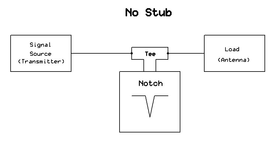 |
| Figure 5: Notch with no "stub" - the result being shown in the plot of Figure 4, above. Click on the image for a larger version. |
Fortunately, there's something that we can do about this: Change the impedance at the resonator in our favor.
If one takes a look at the red circle, we can see that the resistance at marker #1 is in the area of 15 ohms. If we apply a length of transmission line, we can use it to transform the impedance at the "Tee" connector to do a better job of shunting RF at a particular frequency.
Here's what happens if a 1/4 wavelength stub is connected between the "Tee" and the notch filter, connected in the manner depicted in Figure 7:
 |
| Figure 6: The "notch" with a 1/4 wavelength stub inserted between the Tee and the resonator. As we can see, the notch depth is greatly increased - around 25dB - but the response isn't particularly useful! Click on the image for a larger version. |
 |
| Figure 7: A stub between the tee and notch element. As can be seen in Figures 6 and 7, the length of this stub can change the depth of the notch and the "shape" of the notch and the attenuation of the nearby frequencies that are not to be notched out. Click on the image for a larger version. |
- The frequency "distance" between the notch and the peak is now too wide - greater than the width of the 20 meter band. This means that this configuration is not really usable for our intended purpose.
- There is now an asymmetry in the response: The "peak" (minimum attenuation) is lower in frequency than the notch.
 |
| Figure 8: The same arrangement as in Figure 4, but with a shorter cable - one that is approximately 0.15 wavelength. The VSWR is acceptable with radios with built-in tuners - but careful adjustment of coupling and stub length could bring more of the red circle to the 50 ohm "center" of the green circles of the Smith plot. Click on the image for a larger version. |
In figure 8, a shorter cable was used - one that was about 0.15 wavelength of RG-8 type cable. As figure 8 shows, the attenuation isn't as great - around 10 dB - but we we see that there is minimal effect on frequencies above 14.2 MHz and we see something else that is interesting: An asymmetrical response that works in our favor: There is less attenuation above the notch - where our SSB operation is to occur - than below it. This "trick" is frequently used in notch filters - such as those used for repeater duplexers - to increase both the notch depth and provide an asymmetry that favors the frequency at which one wishes to have the least amount of attenuation, typically done with the use of parallel (shunt) capacitance and inductance - both being things that I have yet to try with these filters.
Its worth noting that even though there was a frequency shift with this stub, it was much less than that depicted in Figure 6, so I was able to easily re-tune it.
Two notch filters cascaded:
As it happens, I do have two devices that may be used as a notch resonator - the second one being the band-pass resonator - if I use only one of its ports. The results are as follows:
 |
| Figure 9: The result of cascading two notch filters. The insertion loss is only slightly higher, but the notch depth is now over 20dB. In reality, the second "notch" filter was just the band-pass filter with only one of the two ports connected. A bit more tweaking would likely have reduced the insertion loss and brought the "pass" frequencies' matches closer to 50 ohms. Click on the image for a larger version. |
In this test I placed two notch filters in succession as depicted in Figure 10 - using 0.15 wavelength stubs between the two "tee" connectors (and notch resonators) and between the tees and the resonators themselves: For some reason, I seem to have a bunch of RG-8 jumpers of about that length - around 0.15 wavelengths at 20 meters, which works out to be in the area of 7-8 feet (a bit over 2 meters) physical length, so that is what I used.
 |
| Figure 10: Two notch elements connected with stubs to improve performance. With properly selection of stub length, not only can the notch depth be "greater than the sum of the parts", but the actual shape of the response can be adjusted. For Figure 9, all of the stubs had an electrical length of approximately 0.15 wavelength - but no additional testing was done with other lengths at this time. Click on the image for a larger version. |
As Figure 9 shows, the notch depth is a bit over 20 dB and there is only a slight increase in insertion loss to the 20 meter SSB frequencies: Clearly, this configuration is definitely having a significant effect on the undesired CW/SSB signal and would probably solve most in-band overload issues!
Final comments:
No doubt different (better!) results could have been obtained with different stub lengths and configurations along with the use of parallel (shunt) capacitance and inductance to produce an asymmetrical responce, but I have only so much time and not all that many random chunks of cable on hand and, more importantly, until(?) I construct another notch and pass resonator, I won't be able to use two cavities in the field.
One thing that is difficult to predict before-hand is the effect of source and load impedances other than ideal 50 ohm resistive that would be present with the output (transmit) and input (receive) impedances of HF transceivers, which are "nominally" 50 ohms: In reality, these impedances can vary quite a bit (even between receive and transmit on the same radio!) and these differences can have an effect on the precise amount of attenuation that will be seen. Practically speaking, it will be the transmit loss that will be considered - and this will also be affected by the radio's built-in antenna tuner, if it is inline. Yet another factor that will affect the performance is the match of the connected antenna - particularly as seen at the far ("radio") end of the feedline - especially if a tuner is used there, too.
* * *
What would I do different if I construct more of these things? As noted in the original June 30, 2014 blog entry (linked here) a major weak point of these resonators is the physical construction of the capacitive coupling probes: They are not easy to adjust, and they are quite fragile - a good "jar" of the filter (pun intended!) can knock things out of position and cause detuning. Having a means of being able to adjust the coupling without disassembly - perhaps the use of plastic screws accessible from outside the filter - would be very useful, allowing both critical coupling and tuning to be better-achieved while greatly improving ruggedness.
Perhaps, that will be a future project.
* * *
This page stolen from ka7oei.blogspot.com
[End]