Showing posts with label overload. Show all posts

Friday, June 13, 2025

A 15 (and 10) meter high-pass filter for Field Day

QRM from a transmitter to receivers on lower bands

[Go to the end of this article for an "After-Field-Day follow-up" about this filter] 

A friend of mine belongs to a club in a town north of me and he was describing an issue that they've been having for the past several years during ARRL Field Day:  A station on an upper band (e.g. 15 or 10 meters) degrading reception on 20 or even 40 meters when transmitting.  What was needed was something that could be used on both 15 and 10 meters and protect the lower bands (e.g. 20, 40 and 80) meters - and this protection would go the other way, preventing the 15/10 meter station's receiver from being overloaded by transmissions on the lower bands.

Figure 1:
Exterior of the 15 Meter high-pass filter,
built into a die-cast aluminum box with single-hole
UHF connectors on the sides.
Click on the image for a larger version.

First, a bit of background.

The ARRL Field Day event is held on the fourth (but not last) full weekend every June.  During this event thousands of clubs and individuals go forth into the wilds to set up and operate an event where they attempt to contact as many stations as they can in a 24 (or 27) hour period.  In the case of club stations - or where multiple individuals are involved - it's very common to have more than one transmitter at a given site.

As the Field Day rules stipulate that all antennas/radios be within a 1000 foot (305 meter) circle it isn't possible to provide much geographical separation between different transmitters.  This separation is important because a transmitter produces a very strong signal and the received signals are very weak by comparison:  Receivers can be easily overloaded by these nearby strong signal sources and transmitters can produce low-level signals on frequencies other than those on which they are operation - ones that are too weak to cause problems under normal situations but when placed in close proximity to a receiver these weak emissions can block out/interfere with other receivers - even on different frequency bands.

Other-band signals can cause problems

The degree to which a transmitter radiates these low-level spurious signals - and that to which a receiver is able to tolerate a very strong signal - depends considerably on the transmitter/receiver itself.  Some high end makes of radios (e.g. Elecraft, Flex Footnote 1) can be very clean in terms of transmitted spectra and higher-end receivers of all makes may be capable of tolerating a very strong signals - perhaps even in the same band - and this strategy works as long as the potentially-interfering transmitter itself is clean:  If that "other" transmitter is producing noise at any frequency of reception, there's nothing that can be done at that receiver to fix the problem other than to quiet or clean up the errant transmitter.  Meanwhile, even a "good" radio - such as an Icom IC-706MK2G or IC-7300 Footnote 2 or a Yaesu FT-757 - which works well by itself - may not "play nice with others" when immersed in an environment with multiple transmitters and receivers in very close quarters for reasons largely related to their design architecture.

What this means is that if one uses directional antennas (e.g. Yagis or beams) they are often placed north-south of each other and pointed parallel  Footnote 3 so that there is some isolation off to the sides of these antennas - and it goes without saying that antennas of any sort are separated as far as the rules - or the operating space (e.g. park, yard, forest clearing) allows.

Sometimes, this isn't enough:  Interference can result despite the precautions (e.g. transmit/receiver separation) so additional filtering may be necessary.

The use of Band-Pass filters

Barring the ability to separate antennas or place them in each others' nulls, there are other options:  From a number of manufacturers Footnote 4 there are available band-pass filters that - as the name implies - are designed to pass one specific amateur HF band with low attenuation (loss) while offering significant rejection of other bands above and below.  By placing one of these filters inline with the radio and the antenna, it not only will reduce the probability that a very strong signal from another band might overload the receiver (a particular problem with a radio like the Icom IC-7300 and certain models of other radios from other manufacturers) but it also attenuates the broad-band noise Footnote 5 that almost all HF radios produce that can encompass frequencies other than the band on which they are operating.

This low-level interference - often in the form of a white noise (or hiss) is produced by the amplifier stages in the transmitter itself.  Most modern HF transceivers - while equipped with low-pass filters that attenuate harmonics at multiples of the transmitted signal and generally prevent this noise from being emitted on the next-higher non-WARC band - do NOT have an equivalent high-pass filter in them that prevents low-level spurious signals or broadband noise from being output to the antenna on frequencies below that on which it is operating.  What this means is that a transmitter operating on, say, 15 meters, can produce a "hiss" that may degrade reception on 20, 40 or even 80 meters whenever it is keyed up - in this example, depending on how well that 15 meter antenna can radiate such signals and how close the two antennas are to each other.  (I discussed this very problem in an early article of this blog:  Getting the rigs ready for Field Day - Link).

For this reason it is often preferable to use a band-pass filter on every transmitter that is used, for the specific band on which it will be operated:  This will not only protect that receiver from the other bands' signals but also prevent the low-level energy from being emitted on bands other than that on which it is being used.

Note:  If you are experiencing interference from another transmitter that is actually producing noise on your receive frequency (this, given the presumption that your receiver isn't being overloaded) the addition of a filter on the station receiving interference will do no good at all since it cannot possibly filter out interference that is already there, on-frequency.  In this case, the only appropriate remedy would be to filter the offending transmitter.

As an aside:  In some cases simply enabling the radio's built-in antenna tuner - or using an external tuner - may significantly reduce the amount of out-of-band energy that the transmitter emits as well as adding to the attenuation from "other-band" signals during receive. Footnote 6 

A high-pass filter

While band-specific filters are preferred, my friend presented a case where a high-pass filter (one that blocks signals below a certain frequency) may be appropriate.  In his Field Day environment there has always been a station operating on 20 meters and usually another operating on 40 meters as well - but a third station was available to operate on 15 or 10 meters - depending on propagation conditions.  The problem was that when this third station transmitted, 20 and 40 meters were often degraded - likely by the broadband noise mentioned earlier.

While it would be possible to obtain separate 15 and 10 meter band-pass filters at some expense, I decided on a different approach:  A 15 meter high-pass filter.  This filter - which could be made to strongly attenuate frequencies on the non-WARC amateur bands below 15 meters (e.g. 20, 40 and 80 meters) - it would have the advantage of also being usable on both 15 and 10 meters.  Since it was unlikely that they would have stations on both 15 and 10 meters this strategy seemed sound for their application.

Using the ELSIE program (from Tonne software - link), I first calculated an "N=5" pro-forma high-pass filter using the "Elliptical" (e.g. "Cauer") circuit topology observing that I could get low attenuation at 15 meters and above while achieving more than 40dB on 20 meters and below.  Using the ability of the ELSIE program to do Monte-Carlo type optimizations, I then tweaked the filter topology from a pure Elliptical filter to a hybrid one and this resulted in even better attenuation at 40 meters than the original:  The schematic diagram of this filter is shown below:

Figure 2:
The 15 meter high-pass filter as iterated by the ELSIE program.  The circuit topology - originally
Cauer (Ecliptic) was modified by using simple inductors in sections 1 and 5 and a capacitor at
position 6 and then re-iterated to optimize performance.
Click on the image for a larger version.

As can be seen from the diagram, there are three capacitors in series with the signal path with two inductors directly to ground:  The center inductor is in series with another capacitor, forming one of the "notches" typical of the Elliptical filter topology - and it so-happens that it's possible to tweak the filter so that this notch just happens to land in the middle of the 20 meter band to maximize attenuation there.

Rummaging around in my junk box I found several 500 volt silver-mica capacitors:  For some reason I have a lot of 160pF units, so that was placed at section #2 and three of them were put in parallel for the series capacitor in section #3.  I found a 200pF capacitor for section #6 and I paralleled a 120pF silver mica and an NP0 disc ceramic for that in section #4.

Many people doing homebrew construction seem to intensely dislike toroidal inductors - but while they would be more compact, there is no need to use them here, so large-ish air-core inductors were used.  As the inductors are all "about" the same value (in the 225-300nH range) I wound 7 turns of 17 AWG (but anything 14-18 AWG would do) wire on a 13/32" drill bit for each of them, the precise value being unimportant as their turns would be stretched/compressed while using a VNA to "dial in" the filter response.  As mentioned earlier, I'd added one more inductor from the initial design because the inductors were the cheapest of all of the components (they are just wire!) and they are very adjustable - simply by compressing/spreading the turns which meant that by picking capacitor values that were just "pretty close" to those called out by ELSIE, the coils could be used to tweak the filter's response.  Note in Figure 3 that the inductors that are close-ish to each other are placed at right-angles, or in parallel with each other:  Avoid placing two adjacent coils "end to end" with each other to minimize coupling between them.

Figure 3:
Inside the 15 meter high-pass filter.  Copper-clad PC board
material is used as the backplane (ground) with small pieces
used as "islands" for connection and support points.  The
added capacitor and inductor are those on the right-hand side.
Click on the image for a larger version.

The filter was built on a piece of copper-clad PC board material as a back-plane and ground and small pieces of that circuit board material were cut out to form "islands" - the so-called "Manhattan" construction:  These islands would allow the junctions of the various circuit components to be connected together and with these islands glued to the back-plane and mechanically support the components soldered to them.

The piece of circuit board used as the backplane was sized to fit in the bottom of a die-case aluminum box that I had handy (about 6" x 3.25" x 2" or approx. 15 x 8.3 x 5 cm - but it could have been a bit smaller) onto which I'd installed two chassis-mount UHF connectors:  These connectors were placed rather close to the bottom of the box so that their ground lugs could be soldered to the backplane, providing both the "ground" connection to the copper clad and for mechanical support

Using a VNA, I first adjusted the inductor in section 3 to provide a notch at about 14.24 MHz and then iteratively tweaked the inductors in sections 1 and 5 to provide the lowest insertion loss and lowest VSWR at 15 and 10 meters.  When I was done, the insertion loss was just fine - less than 0.5dB - but the VSWR was about 1.45:1 at 15 and 10 meter so I added two more components (the 30pF capacitor in section 7 and the inductor in section 8 of the diagram) to act as a bit of a "tuner" to improve the match:  In the figure above you can see an inductor (in section 8) that goes to the right-hand UHF connector (6 turns of the same wire as the other coils on a 13/32" drill bit) and a 30pF disk-ceramic capacitor (section 7) between the PC board "island" to which it connects and ground:  With a bit more adjustment of all four inductors this brought the VSWR at 15 and (most of) 10 meters down to about 1.25:1 or better - plenty good enough!  The response of this filter is shown below:

Figure 4:
Insertion loss and VSWR plot of the 15 MHz high-pass filter as plotted by a VNA.
As can be seen, attenuation at 40, 30 and 20 meters is well over 45dB with less than 0.5dB
at 15, 12 and 10 meters:  The VSWR is also acceptably low on these band as well.
Click on the image for a larger version.

Not shown in Figure 3, I later used RTV (silicone) adhesive to stabilize the coils and add support - after tuning, of course:  This reduces the probability of the coils being detuned by the filter being jarred or dropped.  RTV is fairly low loss (at least at HF) and far superior to "hot melt glue" in this case (it's lighter - and it won't melt!) and unlike hot glue or cyanoacrylate (e.g. "Super") glue, it can withstand mechanical shock without breaking loose - even when cold.

This filter should easily handle 100 watts - and the low loss is largely due to the use of silver-mica capacitors:  After all, 500 volt silver mica capacitors - such as those used here - may be found in wide-range antenna tuners made by LDG and the like where they would be exposed to more stress than in the filter.  If you are wondering about the use of the small, disc-ceramic capacitors, they are used in "low stress" parts of the circuit - to "trim" the capacitance to the needed value (e.g. a NP0 ceramic in parallel with a 120pF silver mica to get about 130pF) or used to "tune" the filter as in the case of the 30pF capacitor on the output.  While it might seem risky to use these tiny ceramic capacitors at 100 watts, a quick look at almost any Japanese-made amateur HF transceiver - particularly those made up until fairly recently - you'll find them sprinkled with these capacitors in the low-pass filters and even for matching in the final amplifiers - both at HF and VHF/UHF - for matching:  If it works for them, I'll not worry about using them here in the right places.

Don't forget to change the filter when you change bands!

One hazard with outboard filters of any type:  Be sure that the filter is removed if you attempt to transmit on a frequency for which it is not designed!  After nearly every Field Day I hear/read reports where someone - say, originally on 20 meters - then tries to QSY to another band with the 20 meter filter still inline using the radio's built in antenna tuner or an outboard tuner:  The result is is often that the filter is damaged!  Footnote 7 

Final comments

As can be seen from the response plot of Figure 4 this filter will attenuate signals on the bands 20 meters and below by more than 45dB and this should be enough to quash to inaudibility any low-level noise produced by the transceiver at these lower frequencies that might degrade reception on these bands.  Similarly, energy from transmissions on 20 meters and lower from other stations will be at a much lower level prior to reaching the front end of the radio using this filter, further reducing the probability that they could overload/cause noise.

One thing that has not been discussed thus far is the fact that harmonically-related frequencies (e.g. a transmitter on 7.05 MHz would have harmonics at 14.10 and 21.15 MHz) are likely to be audible on other receivers, despite heroic attempts to fully-filter them.  The reason for this is that these harmonically-related signals will be fairly strong compared to the noise floor of the amateur bands and, unlike the low-level noise discussed earlier, would have their energy concentrated into a small bandwidth.  

Such signals are also likely to be radiated not only from the antenna ports, but from other cables connected to the radios themselves - namely the power cables, audio/microphone connections, data and PTT lines which means that a filter on the output won't suppress those other leakage sources.  Other than wide-spaced separation (e.g. not placing radios in the same location and moving them as far apart as possible) there's no way to completely prevent harmonically-related QRM other than to coordinate efforts and simply avoid operations that could result in harmonically-related interference.

As it is not yet Field Day, I don't know if this filter will "fix" the problem that my friend was reporting, but  should help, and it was quick, cheap and easy to throw together. Footnote 8

* * * * *

After-Field-Day follow-up

A few days after 2025 Field Day I spoke again with the friend for whom I constructed the filter described above. While 10 meters was mostly dead, 15 meters was reasonably productive at times and operation on that band was successfully carried out - mostly using digital modes.

There was time to do a bit of A/B testing and it was noted that without the high-pass filter, the 15 meter transmitter did produce a very audible "hiss" on lower bands - most notably 40 meters - when it keyed up, but this was totally absent with the filter in place.  Additionally, a slight amount of QRM from the lower-band stations (on 80, 40 and 20 meters) transmitting was noted in 15 meter reception without the filter - likely due to strong signals impinging on the radio's internal switching diodes - but this was also absent with the high-pass filter installed.

It's also worth noting that several other tactics were employed to minimize the possibility of QRM (interference) between stations, including:

  • Separating antennas as much as practical.  Depending on the site - not to mention the "1000 foot" rule - you can do only so much, but it helps to carefully consider the layout of the site to maximize distance between antennas.
  • Using band pass filters.  These go a long way toward preventing interference to and from radios on other bands. 
  • Use of mains filters.  L/C filtering (e.g. filters using inductors/capacitors) were installed on the long extension cords that fed the individual stations to prevent RF from being conducted on the electrical power leads and for this, "Isobar" plug strips were used.  Alternatively, putting a half-dozen or so turns of the extension cord through an FT-240 or "Monster" toroid (using 31 or 43 material for either one) would work as well - but it's recommended that the toroid be protected from damage by putting it in a box (e.g. a plastic electrical box with notches to allow the cord to pass).
  • The use of "balanced" 4:1 baluns.  As it turns out, most "4:1" baluns are NOT very balanced - and as such they will put significant RF current onto the radio and feedline, not only reducing antenna efficacy but also potentially improving susceptibility of RFI (Radio Frequency Interference) both TO the radio and devices connected to it (e.g. computers, other radios) but also allow RF interference (from generators, switching supplies, lighting, computers, etc.) to find their way onto the feedline.  This "un-balanced" nature of most baluns can be proven by noting signal strength of a consistent off-air signal and disconnecting only one side of the feed to the balun:  With a truly balanced balun you should see signals reduce by 20dB (3-5 S-units, depending on the radio) or more, but with most baluns you will see only a small (6-10 dB - 1-2 S-units) at most.  Of all of the commercial offerings, one of the very few truly "balanced" baluns is the Balun Designs "Hybrid" balun (Model 4116 - link) - but most 4:1 baluns can be made to be balanced by immediately preceding it with a common-mode current choke (e,g, 8-14 turns of coax on an FT240-31 or FT-240-43 toroid).

 * * * * *

This page stolen from ka7oei.com

[END]

Footnotes:

  1. Unlike most radios, Flex radios do include filtering to prevent low-level noise from being emitted on bands lower than the one on which it's being operated:  Specific models of other manufacturers may also include this - although most do not.
  2. Direct-sampling receivers such as that of the IC-7300 have "different" problems in the presence of very strong signals compared to more conventional superheterodyne receivers:  Any signal that hits the analog-to-digital converter can cause overload, no matter the frequency.  While a conventional receiver can have a very "strong" mixer and some "roofing" filters in its IF (Intermediate Frequency) stages, this is not possible on a direct-sampling receiver.  Instead, it must rely on a rather large number of individual, overlapping band-pass filters to cover its intended frequency range and the ultimate attenuation of these filters may not be "strong" enough to prevent a nearby transmitter on another band from adding to the already-strong melee of signals on the crowded bands during Field Day and causing overload - or, at least, significant de-sensing (e.g. reduction in sensitivity).  This property is also what almost certainly makes them very poor candidates for being able to tolerate another local transmitter on the same band (e.g. a 20 phone and a 20 CW/digital station at the same Field Day site).  There are strategies that can improve the probability of two stations co-habitating on the same band - mostly having to do with picking the "right" radios (e.g. Elecraft K3S or the K4HD are known to work in this environment as are a few others) - as can the use of parallel-pointed Yagi antennas (see the next section, below) - or very "sharp" band-pass and notch filters can be constructed as described in two articles on this blog, namely:  A 100 watt "Helical" resonator bandpass/notch filters to increase isolation of 20 meter stations during Field Day (link) and Revisiting the 20 meter "helical resonator" band-pass/notch filters (link).
  3. Being able to point beams parallel to each other is at least partly a matter of geography.  A station on the east coast is likely pointing their antennas west while the situation would be reversed on the west cost:  A station in the middle of the country - with signals coming from potentially all directions - would be less-likely to be able to use this tactic, at least not without a degree of coordination among the individual transmitters/stations.
  4. A number of different manufacturers make band-specific filters for HF.  Depending on the design, these can offer modest (>=30dB) adjacent-band suppression - which is usually enough to solve most interference problems - or much higher degrees of filtering, even more than 50dB.  In addition, individual-band "Notch" filters are available from some suppliers that reject a specific band of frequencies which can be used several ways - on a transmitter to suppress any low-level noise that it might be generated on a specific band, or on another station to reduce the levels from a transmitter on that other band to prevent overload - and it can also be used to further-improve performance of a band-pass filter and increase attenuation on that specific band.  One of the companies that supplies such filters is Morgan Manufacturing (link):  Full disclosure - I know the person that runs this company and am quite familiar with the products.  Other manufacturers also make similar, excellent products as well.
  5. This "hiss" can usually be detected without any sort of special equipment.  To do this, one would set up two transceivers in a relatively RF-quiet location (perhaps NOT a suburban home), each on its own antenna spaced within a few hundred feet/meters of each other.  On the radio doing the transmitting turn down the microphone gain all of the way after verifying that the RF power output would otherwise yield 100 watts peak when talking.  On the receiver, tune in the next band lower than the transmitter and note the noise floor with and without the transmitter keyed up.  In many cases, a "hiss" that can mask weak signals can be observed - particularly if using a resonant antenna on the transmitter without an antenna tuner.  If you couple carefully into the transmitter (using attenuators or directional couplers) this noise floor can be measured directly with a spectrum analyzer - even the $50-ish "TinySA" is up to the task!  It also goes without saying that a transmitter that IS outputting full power will also be prone to producing such hiss as well - not only above and below its actual transmit frequency, but on the "lower" bands as well.
  6. Testing to determine the efficacy of the built-in tuner as a band-pass filters was done using a Kenwood TS-450SAT, a radio from the 1990s.  When the tuner was switched in and "tuned" - even if the load was already matched - it functioned as a low-Q band-pass filter that reduced the broadband noise and adjacent band signals by at least 8dB - and typically 20dB or so.  Whether or not this strategy is likely to work on specific radios (e.g. some may switch out the tuner if there is already a good match) would require testing as described above.  (These measurements were discussed in a very early entry of this blog - link).
  7. The most likely components to be damaged when trying to "force feed" RF on the "wrong" band are the capacitors, followed by toroidal inductors being somewhat less-likely - and this will often happen when transmitting is attempted at full power (100 or more watts) rather than at the low power level used for tuning.  Usually, the operator realizes the mistake after the tuner fails to find a match, or it does find a match but signals are weak or absent.  For this reason, if you are using a filter with a radio and an external tuner it's strongly recommended that you place the filter between the radio and the tuner:  This will prevent damage to the filter as the radio will protect itself if it's used on the wrong band, presumably alerting the operator to the problem!
  8. It took far longer to put together this article than it did to design, gather parts, assemble and tune the filter!


Monday, September 4, 2023

Measuring signal dynamics of the RX-888 (Mk2)

As a sort of follow-up to the previous posting about the RX-888 (Mk2) I decided to make some measurements to help characterize the gain and attenuation settings.

The RX-888 (Mk2) has two mechanisms for adjusting gain and attenuation:

  • The PE4312 attenuator.  This is (more or less) right at the HF antenna input and it can be adjusted to provide up to 31.5dB of attenuation in 0.5dB steps.
  • The AD8370 PGA.  This PGA (Programmable Gain Amplifier) can be adjusted to provide a "gain" from -11dB to about 34dB.

Note:

While this blog posting has specific numbers related to the RX-888 (Mk2), its general principles apply to ALL receivers - particularly those operating as "Direct Sampling" HF receivers.  A few examples of other receivers in this category include the KiwiSDR and Red Pitaya - to name but two.

Other article RX-888 articles:

RX-888 Thermal issues:  I recently posted another article about the RX-888 (Mk2) discussing the thermal properties of its mechanical construction - and ways to improve it to maximize reliability and durability.  You can find that article here:  Improving the thermal management of the RX-888 (Mk2) - link. 

Using an external clock with the RX-888:  The 27 MHz external clock input to the RX-888 is both fragile and fickle.  To learn a bit more about how to reliably clock an RX-888 from an external source, read THIS article.


* * * * *

Taking measurements

To ascertain the signal path properties of an RX-888 (Mk2) I set its sample rate to 64 Msps and using both the "HDSDR" and "SDR Radio" programs (under Windows - because it was convenient) and a a known-accurate signal generator (Schlumberger Si4031) I made measurements at 17 MHz which follow:

Gain setting (dB)Noise floor (dBm/Hz)Noise floor (dBm in 500Hz)Apparent Clipping level (dBm)
-25-106-79>+13dBm
+0-140-113+3
+10-151-124-8
+20-155-128-18
+25-157-130-23
+33-158-131-31

Figure 1:  Measured performance of an RX-888 Mk2.  Gain mode is "high" with 0dB attenuation selected.

For convenience, the noise floor is shown both in "dBm/Hz" and in dBm in a 500 Hz bandwidth - which matches the scaling used in the chart below.  As the programs that I used have no direct indication of A/D converter clipping, I determined the "apparent" clipping level by noting the amplitude at which one additional dB of input power caused the sudden appearance of spurious signals.  Spot-checking indicated that the measured values at 17 and 30 MHz were within 1 dB of each other on the unit being tested.

Determining the right amount of "gain"

It should be stated at the outset that most of the available range of gain and attenuation provided by the RX-888's PE4312 step attenuator and AD8370 variable gain amplifier are completely useless to us.  To illustrate this point, let's consider a few examples.

Consider the chart below:

Figure 2:  ITU chart showing various noise environments versus frequency.

This chart - from the ITU - shows predicted noise floor levels - in a 500 Hz bandwidth - that may be expected at different frequencies in different locations.  Anecdotally, it is likely that in these days of proliferating switch-mode power supplies that we really need another line drawn above the top "Residential" curve, but let's be a bit optimistic and presume that it still holds true these days.

Let us consider the first entry in Figure 1 showing the gain setting of 0dB.  If we look at the "Residential" chart, above, we see that the curve at 30 MHz indicates a value very close to the -113dBm value in the "dBm in 500 Hz" column.  This tells us several things:

  • Marginal sensitivity.  Because the noise floor of the RX-888 (Mk2) and that of our hypothetical RF environment are very close to each other, we may not be able to "hear" our noise floor at 30 MHz (e.g. the 10 meter amateur band).  One would need to do an "antenna versus no antenna" check of the S-meter/receiver to determine if the former causes an increase in signal level:  If not, additional gain may be needed to be able to hear signals that are at the noise floor.
  • More gain may not help.  If we do perform the "antenna versus no antenna" test and see that with the antenna connected we get, say, an extra S-unit (6dB) of noise, we can conclude that under those conditions that more gain will not help in absolute system sensitivity.

Thinking about the above two statements a bit more, we can infer several important points about operating this or any receiver in a given receive environment:

  • If we can already "hear" the noise floor, more gain won't help.  In this situation, adding more gain would be akin to listening to a weak and noisy signal and expecting that increasing the volume would cause the signal to get louder - but not the noise.  
  • More gain than necessary will reduce the ability of the receiver to handle strong signals.  The HF environment is prone to wild fluctuations and signals can go between well below the local noise floor and very strong, so having any more gain that you need to hear your local noise floor is simply wasteful of the receiver's signal handling capability.  This fact is arguably more important with wide-band, direct-sampling receivers where the entire HF spectrum impinges on the analog-to-digital converter rather than a narrow section of a specific amateur band as is the case in "conventional" analog receivers.

Let us now consider what might happen if we were to place the same receiver in an ideal, quiet location - in this case, let's look at the "quiet rural" (bottom line) on the chart in Figure 2.

Again looking at the value at 30 MHz, we see that our line is now at about -133dBm (in 500 Hz) - but if we have our RX-888 gain set at 0 dB, we are now ((-133) - (-113) = ) 20 dB below the noise floor.  What this means is that a weak signal - just at the noise floor - is more than 3 S-units below the receiver sensitivity.  This also means that a receiver that may have been considered to be "Okay" in a noisy, urban environment will be quite "deaf" if it is relocated to a quiet one.

In this case we might think that we would simply increase our gain from 0 dB to +33dB - but you'll notice that even at that setting, the sensitivity will be only -131dBm in 500 Hz - still a few dB short of being able to hear the noise in our "antenna versus no antenna" test.

Too much gain is worse than too little!

At this point I refer to the far-right column in Figure 1 that shows the clipping level:  With a gain setting of +33dBm, we see that the RX-888 (Mk2) will overload at a signal level of around -31dBm - which translates to a  signal with a strength a bit higher than "S9 + 40dB".  While this sound like a strong signal, remember that this signal level is the cumulative TOTAL of ALL signals that enter the antenna port.  Thinking of it another way, this is the same as ten "S9+30dB" signals or one hundred "S9+20dB" signals - and when the bands are "open," there will be many times when this "-31dBm" signal level is exceeded from strong shortwave broadcast signals and lightning static.

In the case of too-little gain, only the weakest signals, below the receiver's noise floor will be affected - but if the A/D converter in the receiver is overloaded, ALL signals - weak or strong - are potentially disrupted as the converter no longer provides a faithful representation of the applied signal.  When the overload source is one or more strong transmissions, a melange of all signals present is smeared throughout the receive spectrum consisting of many mixing products, but if the overload is a static crash, the entire receive spectrum can be blanked out in a burst of noise - even at frequencies well removed from the original source of static.

Most of the adjustment range is useless!

Looking carefully at Figure 1 at the "noise floor" columns, you may notice something else:  Going from a gain of 0 dB to 10 dB, the noise floor "improves" (is lower) by about the same amount - but if you go from 25 dB gain to 33 dB gain we see that our noise floor improves by only 1 dB - but our overload threshold changes by the same eight dB as our gain increase.

What we can determine from this is that for practical purposes, any gain setting above 20 dB will result in a very little receiver sensitivity improvement while causing a dramatic reducing in the ability of the receiver to handle strong signals.

Based on our earlier analysis in a noise "Urban" environment, we can also determine that a gain setting lower than 0 dB will also make our receiver too-insensitive to hear the weakest signals:  The gain setting of -25dB shown in Figure 1 with a receive noise floor of -79dBm (500 Hz) - which is about S8 - is an extreme example of this.

Up to this point we have not paid any attention to the PE4312 attenuator as all measurements were taken with this set to minimum.  The reason for this is quite simple:  The noise figure (which translates to the absolute sensitivity of a receiver system) is determined by the noise generation of all of the components.  As reason dictates, if you have some gain in the signal path, the noise contribution of the devices after the gain have lesser effects - but any loss or noise contribution prior to the gain will directly increase the noise figure.

Note:

For examples of typical HF noise figure values, see the following articles:

Based on the articles referenced above, having a receiver system with a noise figure of around 15dB is the maximum that will likely permit reception at the noise floor of a quiet 10 meter location.  If you aren't familiar with the effects of noise figure - and loss - in a receive signal path, it's worth playing with a tool like the Pasternack Enterprises Cascaded Noise Figure Calculator (link) to get a "feel" of the effects.

I do not have the ability to measure the precise noise figure of the RX-888 (Mk2) - and if I did do so, I would have to make such a measurement using the same variety of configurations depicted in Figure 1 - but we can know some parameters about the worst-case:

  • Bias-Tee:  Estimated insertion loss of 1dB
  • PE4312:  Insertion loss of 1.5dB at minimum attenuation
  • RF Switch (HF/VHF):  1dB loss
  • 50-200 Ohm transformer:  1dB loss
  • AD8370 Noise figure:  8dB (at gain of 20dB)

The above sets the minimum HF floor noise figure of the RX-888 (Mk2) at about 12.5dB with an AD8370 gain setting of 20dB - but this does not include the noise figure of the A/D converter itself - which would be difficult to measure using conventional means.

On important aspect about system noise figure is that once you have loss in a system, you cannot recover sensitivity - no matter how much gain or how quiet your amplifier may be!  For example, if you have a "perfect" 20 dB gain amplifier with zero noise, if you place a 10 dB attenuator in front of it, you have just turned it into an amplifier with 10 dB noise figure with 10dB gain and there is nothing that can be done to improve it - other than get rid of the loss in front of the amplifier.

Similarly, if we take the same "perfect" amplifier - with 20dB of gain - and then cascade it with a receiver with a 20dB noise figure, the calculator linked above tells us that we now have a system noise figure of 3 dB since even with 20dB preceeding it, our receiver still contributes noise!

If we presume that the LTC2208 A/D converter in the RX-888 has a noise figure of 40dB and no gain (a "ballpark" value assuming an LSB of 10 microvolts - a value that probably doesn't reflect reality) our receive system will therefore have a noise figure of about 22dB.

What this means is that in most of the ways that matter, the PE4312 attenuator is not really very useful when the RX-888 (Mk2) is being used for reception of signal across the HF spectrum, in a relatively quiet location on an antenna system with no additional gain.

Where is the attenuator useful?

From the above, you might be asking under what conditions would the built-in PE4312 attenuator actually be useful?  There are two instances where this may be the case - and this would be applied ONLY if you have been unable to resolve overload situations by setting the gain of the AD8370 lower.

  • In a receive signal path with a LOT of amplification.  If your receive signal path has - say - 30dB of amplification (and if it does, you might ask yourself "why?") a moderate amount of attenuation might be helpful.
  • In a situation where there are some extremely strong signals present.  If you are near a shortwave or mediumwave (AM broadcast) transmitter that induces extremely strong signals in the receiver that cause intractable overload, the temporary use of attenuation may prevent the receiver from becoming overloaded to the point of being useless - but such attenuation will likely cause the complete loss of weaker signals.  In such a situation, the use of directional antennas and/or frequency-specific filtering should be strongly considered!

Improving sensitivity

Returning to an earlier example - our "Quiet Rural" receive site - we observed that even with the gain setting of the RX-888 (Mk2) at maximum, we would still not be able to hear our local noise floor at 30 MHz - so what can be done about this?

Let us build on what we have already determined:

  • While sensitivities is slightly improved with higher gain values, setting the gain above 20dB offers little benefit while increasing the likelihood of overload.
  • In a "Quiet Rural" situation, our 30 MHz noise floor is about -133dBm (500 Hz BW) which means that our receiver needs to attain a lower noise floor than this:  Let's presume that -136dBm (a value that is likely marginal) is a reasonable compromise.

With a "gain" setting of 20dB we know that our noise floor will be around -128dBm (500 Hz) and we need to improve this by about 8 dB.  For straw-man purposes, let's presume that the RX-888 (Mk2) at a gain setting of 20dB has a noise figure of 25dB, so let's see what it takes for an amplifier that precedes the RX-888 (Mk2) to lower than to 17dB or so using the Pasternak calculator above:

  • 10dB LNA with 7 dB noise figure:  This would result in a system noise figure of about 16 dB - which should do the trick.

Again, the above presumes that there is NO  loss (cable, splitters, filtering) preceding the preamplifier.  Again, the presumed noise figure of 25dB for the RX-888 (Mk2) at a gain setting of 20 is a bit of a "SWAG"  - but it illustrates the issue.

Adding a low-noise external amplifier also has another side-effect:  By itself, with a gain setting of +33, the RX-888 (Mk2)'s overload point is -31dBm, but if we reduce the gain of the RX-888 to 20dB the overload drops to -18dBm - but adding the external 10dB gain amplifier will effectively reduce the overload to -28dBm, but this is still 5 dB better than if we had turned the RX-888's gain all of the way up!

Taking this a bit further, let's presume that we use, instead, an amplifier with 3dB noise figure and 8 dB gain:  Our system noise figure is now about 17dB, but our overload point is now -26dBm - even better!

The RX-888 is connected to a (noisy) computer!

Adding appropriate amounts of external gain has an additional effect:  The RX-888 (and all other SDRs) are computer/network connected devices with the potential of ingress of stray signals from connected devices (computers, network switches, power supplies, etc.).  The use of external amplifiers can help override (and submerge) such signals and if proper care is taken to choose the amount of gain of the external amplification and properly choose gain/attenuation settings within the receiver, superior performance in terms of sensitivity and signal-handling capability can be the result.

Additional filtering

Only mentioned in passing, running a wideband, direct-sampling receiver of ANY type (be it RX-888, KiwiSDR, Red Pitaya, etc.) connected to an antenna is asking a lot of even 16 bits of conversion!  If you happen to be in a rather noisy, urban location, the situation is a bit better in the sense that you can reduce receiver gain and still hear "everything there is to hear" - but if you have a very quiet location that requires extra gain, the same, strong signals that you were hearing in the noisy environment are just as strong in the quiet environment.

Here are a few suggestions for maximizing performance under the widest variety of situations:

  • Add filtering for ranges that you do not plan to cover.  In most cases, AM band (mediumwave) coverage is not needed and may be filtered out.  Similarly, it is prudent to remove signals above that in which you are interested.  For the RX-888 (Mk2), if you run its sampling rate at just 65 MHz or so, you should install a 30 MHz low-pass filter to keep VHF and FM broadcast signals out.
  • Add "window" filtering for bands of interest.  If you are interested only in amateur radio bands, there are a lot of very strong signals outside the bands of interest that will contribute to overload of the A/D converter.  It is possible to construct a set of filters that will pass only the bands of interest - but this does not (yet?) seem to be a commercial product.  (Such a product may be available in the near future - keep a lookout here for updates.)
  • Add a "shelving" filter.  If you examine the graph in Figure 2 you will notice that as you go lower in frequency, the noise floor goes UP.  What this means is that at lower frequencies, you need less receiver sensitivity to hear the signals that are present - and it also means that if you increasingly attenuate those lower frequencies, you can remove a significant amount of RF energy from your receiver without actually reducing the absolute sensitivity.  A device that does just this is described in a previous blog article "Revisiting the limited-attenuation high-pass filter - again (link)".  While I do not offer such a filter personally, such a device - along with an integrated 30 MHz low-pass filter - may be found at Turn Island Systems - HERE.

Conclusions:

  • The best HF weak-signal performance for the RX-888 (Mk2) will occur with the receiver configured for "High" gain mode, 0 dB attenuation and a gain setting of about 20dB.  Having said this, you should always to the "antenna versus no antenna" test:  If you see more than 6-10dB increase in the noise level at the quietest frequency, you probably have too much gain.  Conversely, if you don't see/hear a difference, you probably need more gain - taking care in doing so.
  • For best HF performance of this - or any other wideband, direct-sampling HF SDR (RX-888, KiwiSDR, Red Pitaya, etc.) additional filtering is suggested - particularly the "shelving" filter described above.
  • In situations where the noise floor is very low (e.g. a nice, receive quiet location) many direct-sampling SDRs (RX-888, KiwiSDR, Red Pitaya) will likely need additional gain to "hear" the weaker signals - particularly on the higher HF bands.  While some of these receivers offer onboard gain adjustment, the use of external high-performance (low-noise) amplification (along with filtering and careful adjustment of the devices' gain adjustments) will give improved absolute sensitivity while helping to preserve large-signal handling capability.
  • Because the RX-888 is a computer-connected device, there will be ingress of undesired signals from the computer and the '888's built-in circuitry.  The use of external amplification - along with appropriate decoupling (e.g. common-mode chokes on the USB cable and connecting coaxial cables) can minimize the appearance of these signals.


This page was stolen from ka7oei.blogspot.com.

[End]


Saturday, May 22, 2021

Characterizing the RTL-SDR Blog (Version 3) for HF reception using the "direct" input.

An inexpensive option for SDR (Software Defined Radio) reception on the HF (low frequency) bands is a device sold by "RTL-SDR Blog" - the current iteration being Version 3.  Originally intended for digital VHF/UHF TV reception - and that of FM broadcast - the hardware is also capable of tuning much lower frequencies.

Figure 1:  An RTL-SDR Blog V3 USB receiver "dongle".
Unlike most other inexpensive RTL-SDR dongles, this has - via a single SMA port - the ability to operate in "direct" mode where RF below the VHF frequencies is passed straight to the A/D converter rather than via a down-converter, allowing reception from (theoretically) a few hundred kHz to around 30 MHz.

How does it do this?

The typical RTL-SDR Dongle actually consists of two tunable devices:

  • The Rafael R820T.  This is simply a frequency converter, capable of handling an input signal from somewhere below 60 MHz into the GHz range and converting it to what we'll call an "IF" (Intermediate Frequency) which is much will likely be below 12 MHz.  In addition to having a programmable oscillator and mixer for frequency conversion, his device has some built-in filtering that provides some protection to strong-ish off-frequency signals, and it has an AGC (Automatic Gain Control) that can adjust the level being output from it to prevent overload of the A/D converter as well as some front-end attenuation control to reduce the likelihood of overload on the input.
  • The Realtek RTL2832U.  The down-converted output of the R820 chip is passed to this device, which consists of two 8 bit A/D (Analog-to-Digital) converters that are clocked at 28.8 MHz (meaning that signals above 14.4 MHz will be "aliased"), a USB interface, a (reported) 8051-type microcontroller and a digital frequency "converter" that is also capable of being "tuned" to produce a quadrature "baseband" signal that is output onto the USB port - the rate being programmable from around 250 ksps to 2880 ksps.  This device does NOT have an AGC or gain/attenuation control.

VHF/UHF operation:

Briefly, reception on the VHF/UHF frequencies is done the following way:

  • A simple high pass filter/diplexer passes only the VHF/UHF signals (e.g. those above approximately 40 MHz) directly to the R820T.
  • The filtering of the R820T is programmed for the desired characteristics at the operating frequency.
  • The frequency converter in the R820T is offset from the input signal to provide an output (IF) signal in the 1-14 MHz range - more likely somewhere between 3 and 6 MHz.
  • The level of this output signal may be automatically controlled by the AGC system of the R820T to keep it within the optimal range of the A/D converter.  Similarly, input gain adjustment on the R820T can prevent it from being overloaded by strong signals.
  • The tuner within the RTL2832U is set to about the same frequency being output by the R820T (likely in the 5-12 MHz range) so that it is within the range of output ("baseband") sample rate, and output via the USB port.

HF operation:

  • The signal to be received is applied via the RF antenna port and diverted from the R820T to a very simple low-pass filter/diplexer to an RF amplifier.  This diplexer's effect begins at approximately 22 MHz - See the discussion near table 1, below.
  • The output of from the RF amplifier is passed through additional filtering and applied to one of the two A/D inputs of the RTL2832U - typically the "Q" input.
  • The tuner within the RTL2832U is set near the frequency to be received so that it is within the range of the output ("baseband") sample rate, and output via the USB port.
  • Because the sample rate of the RTL2832U is 28.8 MHz, any signal above 14.4 MHz will also appear "below" it as well - see the discussion below.

There's a penalty to pay for simplicity:

For those familiar with receiver topology - digital or analog - several things the above description of the HF operation of the RTL-SDR dongle without proper measures (e.g. filtering, gain control) should give cause for concern - namely:

  • There is NO bandpass filtering at all.  Whatever is being intercepted by the antenna system will be input directly to the A/D converter via the preamplifier.
  • ANY signal applied to the antenna input - no matter the frequency - can contribute to overload.  Because the inputted RF goes into the A/D converter, a strong signal well away from where you are listening can cause overload.  For example, if you are listening to 14 MHz, a strong AM broadcast signal (e.g. mediumwave) could well be the culprit if you are experiencing overload.
  • There is no AGC in the HF ("direct") signal path.  Considering that the A/D converter is only 8 bits, this means that compared to even low-end shortwave receivers, the range of signal levels over which this device will operate is very narrow.  The lack of an "AGC" (automatic gain conttrol) means that there will likely not be enough gain when signals are very weak and overload of the A/D converter is likely if the signals are very strong.
  • The A/D converter's sample rate is 28.8 MHz.  What this means is that the Nyquist limit - the frequency above which the digitized output can no longer represent the input signal - is half this, or 14.4 MHz, uncomfortably close to the 20 meter amateur band, and entirely below the 17, 15, 12 and 10 meter bands - and this does not even consider the fact that the sample frequency is within the 10 meter band itself. 
What this means is that there are unsuppressed image responses all across the HF spectrum.  For any frequency you tune below 14.4 MHz, you can also hear any signal above 14.4 MHz, the frequency of which is calculated by subtracting its frequency from the sample rate (e.g. 28.8 MHz).  For example, 15 meter signals will also appear, spectrally inverted (e.g. USB = LSB) 7.80-7.35 MHz.  Image frequencies appear in table 1 - along with MDS and clipping values - below.

In other words, if you are tuned to any HF frequency, you are actually "hearing" TWO frequencies at the same time unless you have specific filtering to prevent such image response.  See the right-hand column of Table 1 (below) for the frequency at which you will see an image.

The above puts strict limits on the performance of the RTL-SDR dongle as an HF receiver and these realities must be considered when the configuring any system that might use them.

The usable dynamic range:

In theory, 8 bits of A/D sampling would indicate about 48dB of useful signal range, but the reality is more complicated than this.  Compared to the bandwidth of the narrow signals typically sought on HF, the overall sample rate of the A/D converter - and even the rate after the RTL2832U's converter has reduced the signal to the sample rate being sent to the USB port - are very much higher, effectively improving the bit depth via oversampling - and the fact that the HF spectrum is backgrounded with what amounts to white noise works to our benefit, helping to spread discrete, spectral artifacts that are the inevitable result of the imperfect signal acquisition.

This also works the other way:  Very strong, discrete signals (e.g. SWBC transmitters) can also cause mixing products which can find their way in other signals - particularly weak ones - but this effect may be minimized if one manages to keep the input level "high enough" so that at least several bits of A/D conversion are involved and also limited such that A/D converter overloads are minimized as much as practical - a balancing act that makes it difficult to handle both weak and strong signals at the same time.

All of this makes the actual, usable range a bit difficult to divine.  To this end, an RTL-SDR (V3) unit was put on the workbench, using the "HDSDR" program as a receiver, and its operation was analyzed by observing CW (unmodulated) signals on narrow (SSB) bandwidths.

Methodology:

Ideally, we would be able to determine the RF level at which the A/D convert clipped directly, but the HDSDR program does not provide a means to see the peak A/D level, requiring us to infer it by noting the level from a known-accurate signal generator at which the S-meter starts to decrease at the same rate that the signal level is reduced - and also by noting the disappearance from the waterfall many of spurious signal caused by overload.  Typically, this is about 3dB below the "maximum" S-meter reading.

For sensitivity, DL4YHF's "Spectrum Lab" program was used to measure the SINAD in a 500 Hz bandwidth set by the HDSDR program, the "minimum discernible signal" being equivalent, in this test, to 3dB S/N.

Table 1:  Measured signal levels for A/D clipping and MDS, along with corresponding image frequencies on HF.  Because the sample rate of the RTL-SDR is 28.8 MHz, ALL signals above half this frequency (e.g. 14.4 MHz) are, by definition, Nyquist images.  The far-right column is "apparent" dynamic range - see the discussion below.
Frequency (MHz)
Clipping (dBm)
MDS (dBm)
Image  (MHz)
Apparent DR (dB)
0.5
-17
-97
28.3
80
1.0
-24
-107
27.8
83
2.0
-27
-109
26.8
82
4.0
-27
-116
24.8
89
7.0
-29
-117
21.8
88
10.0
-30
-117
18.8
87
14.0
-30
-117
14.8
87
15.0
-30
-116
13.8
86
18.0
-30
-116
10.8
86
21.0
-29
-114
7.8
85
24.0
-25
-109
4.8
84
28.0
-14
-95
0.8
81
29.0
-16
-94
0.2
78
35.0
-16
-90
6.2
74
40.0
-2
-84
11.2
82

Discussion:

Table 1 tells us several things:

  1. As mentioned in the documentation found at the RTL-SDR Blog web site, signals below 2 MHz - and especially below 1 MHz - are rolled off by the "Bias Tee" blocking choke which has insufficient inductance at frequencies below the AM broadcast band.  To a degree, this effect can be mitigated by removal of the RF choke which will remove the capability to inject DC onto the cable.  This table includes the effect of this choke.
  2. The RTL-SDR has a low-pass filter to diplex the HF and VHF and above frequencies to separate signal paths, and the effects of this filter are becoming evident above 15 meters (21 MHz).  This also means that by itself, the RTL-SDR becomes "deaf as a post" on the 12 and 10 meter bands.
  3. Note that at the very low frequencies, the sensitivity appears to be somewhat reduced.  The effects of high-pass roll-off - likely caused by coupling capacitors and the input bias inductor - appear to be evident through at least 7 MHz.
  4. There is clearly no image rejection at all, considering that the sensitivity through 21 MHz is comparable to that below 14 MHz.  For example, 15 MHz WWV will also appear on a receiver program at 13.8 MHz, at the same apparent signal strength.
  5. Low-pass effects are evident by 24 MHz, most likely a result of the diplexer used to split the HF (direct) and VHF/UHF signal paths.  This limits sensitivity on the 12 and 10 meter amateur bands.
  6. With only 8 bits of quantization, additional noise will be generated due to the imprecise nature of the process.  This "noise" will show up as spurious signals and, less obviously, as a rise in the overall noise floor - depending on the nature of what is being digitized.  In short, the fewer the number of bits, the less likely it is that weak signals will coexist (and be audible) in the presence of strong signals.
  7. Across most of the HF spectrum, the RTL-SDR will overload signal at about -30dBm - which is approximately equal to an S-meter reading of "40 over S-9".  While this seems like a fairly strong signal, this power level represents the total amount of RF energy - no matter the frequency!
  8. Note that the power at which the A/D converter starts to overload is approximately -30dBm across much of the HF spectrum.  This represents the TOTAL amount of RF power required, at all frequencies combined, that will result in overload.
  9. Across much of the HF and MF spectrum (0.5-28 MHz) the apparent dynamic range is on the order of 80 dB.  This number should be taken with a grain of salt as it was measured in the absence of any other signals -  hardly a real-world equivalent.  Practically speaking, this number is indicative of the best possible performance under ideal conditions.

Points 7 and 8, above, should be considered very carefully in terms of its implications:

  • You cannot simply connect an RTL-SDR Dongle to even an "average" performing HF antenna and expect reasonable results as the total power from ALL signals reaching the receiver are likely to exceed the -30dBm signal level - particularly if you have any AM (mediumwave) transmitters anywhere nearby (e.g. within 20 miles/30km).
  • Particularly on the lower bands (80, 40, 30 meters) the signal levels of amateur and especially shortwave broadcast signals can, by themselves, exceed the -30dBm overload level - particularly in Europe and the eastern U.S. On some bands, the shortwave broadcast band adjacent to the amateur band (e.g. 41 and 40 meters) are too close to effectively filter out and it may be that an RTL-SDR is simply not usable on these bands when propagation favors reception on these frequencies. 
  • As seen in Table 1 (above) the RTL-SDR dongle becomes increasingly deaf on the higher HF bands (particularly 12 and 10 meters) making them unusable at these frequencies without additional amplification AND filtering.  What's worse is that the lower HF frequencies (e.g. below 10 MHz) are typically very noisy while the higher frequencies are quiet by comparison.  If you connect an antenna to the RTL-SDR dongle with no band-pass filtering and try to tune in, say, the 15 meter band, you will likely hear only noise (and signals) around 4.8 MHz, which will likely overwhelm any weak, 15 meter signals.
  • If you plan to use an RTL-SDR for HF reception and expect even mediocre performance, you should precede it with a band-pass filter for the frequency band of interest.  For the highest HF bands (15, 12 and 10 meters) the typical noise floor in a quiet location is around -120 dBm (in a 500 Hz bandwidth) - which is well below the noise floor of the RTL-SDR at these frequency meaning that a preamplifier (along with a bandpass filter) will be required for reasonable performance.
  • It's worth remembering that unlike an analog receive system, one cannot always use all 8 bits for digitization:  The signal input must be kept well below the "full scale" level (at and above which "clipping" will occur, causing distortion and signal degradation everywhere else) to accommodate for random fluctuations that are ever-present on signals input from the antenna.  What this means is that the A/D must be under-driven overall and that fewer bits are actually being used most of the time.  In order to maintain suitable margin, it's typical to drive the A/D converter at between 1/4 and 1/2 full scale, meaning that for 8 bits of A/D conversion, 2-4 bits are typically being used - and fewer, still, when the band is "dead" and signals are weak.

Conclusions:

  • DO NOT simply connect an RTL-SDR to your HF antenna and expect it to work as well as even a low-end shortwave receiver:  If it doesn't get overloaded by local AM broadcast (mediumwave) signals, it will get overloaded by strong shortwave broadcast signals when conditions are favorable on certain bands.  This isn't to say that you won't hear anything if you do so, but know that normal signal levels present on even an "average" antenna will be enough to overload the RTL-SDR dongle.
  • ALWAYS precede an RTL-SDR with a band-pass filter that is specific for the frequency range of interest. For example, if you are interested in 40 meter reception (7.0-7.3 MHz for ITU region 2) your filter should pass only frequencies in this range, and this filtering will prevent unwanted reception of signals at the image frequency around 21.8 MHz.   Unfortunately, the use of a band-pass filter precludes reception outside its design range, but this is necessary considering the limited capability of the RTL-SDR dongle in terms of handling both strong and weak signals at the same time and its unfettered response to unwanted images.
  • In some cases - even with a mediocre antenna - the signals in the desired frequency range may exceed the signal handling capability of the RTL-SDR and cause overload.  As noted above, a single signal stronger than -30dBm can do this, but so could a number of signals whose total power can exceed this.  Typically, this overload is manifest as intermittent distortion across the entire receiver as signals fade in and out.  In such cases, it might be beneficial to attenuate the signals reaching the RTL-SDR as the degradation caused by overload is more "destructive" across the entire receive frequency range than too-little signal.
  • Because of image response and roll-off, the HF port of the RTL-SDR is really not well-suited for 12 and 10 meter (24-30 MHz) reception.

Comment about HF upconverters:

Specifically to address some of these issues, there are upconverters available for the RTL-SDR that will upconvert the HF spectrum to VHF (typically in the 100-130 MHz range) to allow the use of that signal path, making use of the Raphael R820T converter.  This converter has the advantage of having a degree of band-pass filtering and the ability to use AGC (automatic gain control) on the signal path.

This method can be useful, but there are several caveats:

  • If frequency stability is of importance, the addition of the upconverter introduces two additional frequency stability issues:  Drift of the upconverter itself, and the fact that any existing drift in the dongle itself will be multiplied because of its operation at the higher frequency.  This can be an issue in environments where the temperature is not stable and/or when a frequency sensitive mode like SSB or (especially) digital modes are used.
  • If multiple bands and receivers are to be used, there may be the temptation to upconvert the output of the upconverter to VHF and distribute this signal to the receivers.  While this may work in many cases, it's worth noting that if the entire HF spectrum is converted, the total signal power level can be significant, potentially overloading the upconverter itself, any RF amplifiers that might be used at VHF, and/or the front end of the RTL-SDR dongles themselves.
    • While a "fix" might normally be to filter out just the HF band(s) of interest, this can become impractical if the 40 meter band (7.0-7.3 MHz) is upconverted to, say, 137 MHz where it can become difficult to make an effective band-pass filter at that frequency.
    • It is possible to filter for a specific HF band before the upconversion, but this means that each RTL-SDR would require its very own upconverter.  While effective, the cost of an upconverter for each band may be prohibitive.

* * *

Successfully using an RTL-SDR on HF:

As mentioned earlier, one must precede the RTL-SDR with a band-pass filter to obtain reasonable performance on HF - or any other frequency range where very strong and very weak signals will be simultaneously present at the antenna input:  Remember that, especially in the "direct" mode, all signals applied to the RF input - even those MHz away from where the receiver is tuned - will count "against" you in terms of the total amount of RF power that may be applied to the A/D converter before it clips/overloads.

To see some RTL-SDR based HF receive systems in operation - and to be able to directly compare them with higher-performance receivers using the 16 bit signal path, visit the Northern Utah WebSDR site at sdrutah.org (link).  This will take you to a "landing page" where you can select several receivers - specifically:
  • WebSDR #3:  This server uses RTL-SDRs for both the 80 and 40 meter bands.
  • WebSDR #1:  This server uses SDRPlay RSP1a receivers which have both an RF AGC and around 14 bits of A/D converter depth - plus external band-pass filtering.

Both of these systems use the same antenna for 80 and 40 meters and it is possible to directly compare signals between the two in side-by-side windows.  Generally, the 8 bit RTL-SDRs used on WebSDR #3 hold their own compared to those on WebSDR #1, and this is possible only because the WebSDRs are preceded with both band-pass filtering and AGC as described in the link below.

* * *

Additional resources:

  • An article on using band-pass filtering and AGC (Automatic Gain Control) to improve the performance of an RTL-SDR when used for amateur band service may be found here:  http://www.sdrutah.org/info/rtl_sdr_agc.html .  Several "test" receivers are currently in operation at the Northern Utah WebSDR that demonstrate the efficacy of doing this.


 This page stolen from ka7oei.blogspot.com

[End]

Saturday, September 26, 2020

Revisiting the "Limited Attenuation High Pass" filter - again.

In several previous posts (See:  "A Limited Attenuation High Pass Filter" and "Revisiting the Limited Attenuation High Pass Filter" I described a "high pass" filter that offered low attenuation at high HF frequencies, but a controlled amount of attenuation at lower frequencies - this, to accommodate a fundamental fact about both HF propagation and direct-sampling Software Defined Radios (SDRs):  The two don't play nice with each other!

Note:

If you are using any direct-sampling Software Defined Radio to receive ALL of the HF spectrum simultaneously  - such as a KiwiSDR, Red Pitaya, RX-888, RX-666, TRX Duo to name but a few - you SHOULD read this page and understand why it is important to apply such filtering to maximize performance across HF.

In a typical receiver/antenna configuration, failure to reduce the lower HF frequencies with respect to the top of the HF spectrum (e.g. 10 meters) will result in comparatively poor performance.

As noted in the previous post(s), the problem is two-fold when it comes to broad-band SDRs that are intended to cover the entire HF spectrum all at once:
  • HF noise power and signal level is (generally) inversely proportional to frequency.  At lower frequencies - say, 2-8 MHz - the noise power is far higher than it typically is at around 20-30 MHz.
  • A direct-sampling SDR - or any receiver, for that matter - can tolerate only so much RF power on its front end.  Traditionally, this is a mitigated with the use of narrow-band RF band-pass filters, but this can't be done if one intends to be able to cover the amateur radio bands 160 through 10 meters (1.8-30 MHz).
With the aforementioned issues is yet another one:  Because the noise floor at 10 meters when it is "quiet" is so much lower than 80 meters (perhaps 40-50 dB during noisy nighttime conditions, 25 dB or so during quiet daytime conditions) there is an intrinsic disparity between the amount of sensitivity that is need to "hear everything" at the opposite ends of of the HF spectrum - but since a typical direct-sampling SDR is pretty much "flat", we end up with what might seem like a pair of intractible problems:
  •  To accommodate the very strong signals and high noise levels at lower HF frequencies, the RF signal gain in front of the A/D converter must be carefully set to prevent overload.
  • In order to "hear" the noise floor at 10 meters, the system gain must be set fairly high.

What these two factors, together, imply is that if we have enough gain to comfortably detect the noise floor at 10 meters, our receiver will be badly overloaded during strong-signal conditions on the lower bands.  Conversely, if we scale (e.g. attenuate) the input to accommodate the very large signal excursions, the receiver will simply be unable to detect signals at/near the "quiet" 10 meter noise floor.

Comments:
There will (hopefully) be the day that the upper HF propagation conditions improve greatly with the arrival of solar cycle 25 and at that time, strong signals will appear on the bands >=15 MHz.  When this happens, we will likely be faced with a problem similar to that which we are trying to solve here (e.g. very strong signals overloading the A/D converter).  At this time, the only recourse will likely be a means of using an external device to adjust the gain/attenuation in front of the receiver, probably using the existing I/O lines under receiver control.
Since the original posting of this blog entry I was made aware of an 1977 article on this very topic - you can read it HERE. (The article in question begins on page 3 of the PDF.)

A revised circuit:

Why talk about this issue a THIRD time?  I decided to make one that provided a better 50 ohm match across all frequencies than the previous versions.  This revised circuit may be seen in the figure below:

Figure 1:
Generic pre-emphasis network set for about 50 ohms.
Click on the image for a slightly larger version.


Some readers will recognize the topology of the circuit in Figure 1 as the classic pre-emphasis network found in the signal  path of FM video transmitters.  Whereas those circuits are typically designed for 75 ohms, this one is intended for a 50 ohm system - but careful observers will notice that 47 ohm resistors are used, instead:  For receive-only purposes, I have chosen the components in this article to be standard values at the expense of a slight increase in mismatch - but the VSWR of these circuits, when terminated at 50 ohms - is likely to be no more than about 1.1:1.

This circuit - compared with the previous versions - has the advantage that it presents a consistent source and load impedance across the frequency range, making it a bit more "friendly" in systems that may be impedance sensitive (e.g. following a band-pass filter, long coaxial cable runs, following/preceding conditionally-stable RF amplifiers.)  The obvious trade-off is that as compared to the previous version (which was based on a high-pass filter and some resistive bypassing) this circuit has definite limitations on how sharp and deep the "knee" may be at any given frequency as only a single inductor and capacitor are used.

By tweaking the values of R1, R4, C1 and L1 we can adjust both the amount of low-frequency attenuation and the frequency of the "knee" where the attenuation takes place - but for our purposes, we will be placing the center of that "knee" around 10 MHz to provide both the minimal loss at 30 MHz and adequate attenuation at and below 7 MHz.

Here are a few examples of values of R1, R4, C1 and L1 using standard-value components and approximate attenuation values at various frequencies:

R1 = 68 ohms  R4 = 39 ohms
C1 = 390pF  L1 = 1uH
DC attenuation:  7.3dB
@ 2 MHz: 7.0dB  @4 MHz: 6dB
@ 7 MHz: 4.6dB  @10 MHz: 3.4dB
@ 14 MHz: 2.3dB  @28 MHz: 0.8dB
R1 = 120 ohms  R4 = 20 ohms
C1 = 330pF  L1 = 0.82uH
DC attenuation:  10.8dB
@ 2 MHz: 9.8dB  @4 MHz: 8.1dB
@ 7 MHz: 5.6dB  @10 MHz: 3.9dB
@ 14 MHz: 2.5dB  @28 MHz: 0.8dB
R1 = 120 ohms  R4 = 20 ohms
C1 = 270pF  L1 = 0.68uH
DC attenuation:  10.8dB
@ 2 MHz: 10.1dB  @4 MHz: 8.7dB
@ 7 MHz: 6.5dB  @10 MHz: 4.8dB
@ 14 MHz: 3.3dB  @28 MHz: 1.2dB
R1 = 100 ohms  R4 = 27 ohms
C1 = 270pF  L1 = 0.68uH
DC attenuation:  9.4dB
@ 2 MHz: 8.9dB  @4 MHz: 8dB
@ 7 MHz: 6.3dB  @10 MHz: 4.8dB
@ 14 MHz: 3.6dB  @28 MHz:1.3dB

Figure 2:
Table showing some possible values for the circuit of Figure 1 and the example attenuation values.


In practice, several of these sections will likely need to be cascaded to achieve the desired amount of attenuation at the lower HF frequencies which brings up the question:  Could you not choose components to do this for a single section?  The answer is theoretically, yes - but the fact is that practical inductors - particularly the molded type - are quite lossy, departing from the intended attenuation curve, and achieving the predicted, higher amount of lower-frequency attenuation with a single stage can become problematic - so it's probably better to cascade several of these networks together, instead.

A practical example:

Figure 3:
The exterior of the four channel filter network.
Click on the image for a larger version

A practical example of such a network is one that is to be currently installed in the KFS (Half Moon Bay, CA) KiwiSDR/WSPRDaemon system.  There, four wideband antennas are available to feed the KiwiSDRs on site, so a box was constructed with four, identical pre-emphasis networks, each to feed its own receiver stack.

As is the case at the Northern Utah WebSDR, noise and signals at the lower end of the HF spectrum is often very much stronger than at the high end:  If amplification is added to allow the detection of the noise floor at 10 meters, there is the very high probability that the receiver will badly overload on HF signals from the lower end of the spectrum.

Each "channel" of the device depicted in Figure 3 is identical, consisting of two cascaded sections.  The first section is that from the upper-left quadrant of the table (R1=68 ohms, C1 = 390 pf) and the upper-right quadrant (R1=120 ohms, C1 = 330pF).  Rather than the use of molded chokes, the individual inductors were wound using 30 AWG wire on T25-2 toroids:  17 and 15 turns for the 1 uH and 0.82 uH inductors, respectively.

Figure 4:
The interior of the four-channel network.
The circuit is simple enough to be wired "Manhattan"
style on glass-epoxy PC board material between the
two center pins of the BNC connectors.
Click on the image for a larger version

As can be seen in Figure 4, the construction is very simple, requiring no circuit board at all when using standard, through-hole components.  The circuit was built into a die-cast aluminum box with the BNC connectors holding the piece of PCB material in place.

To secure the components - particularly the small, toroidal inductors - RTV sealant (white) was used to hold components in place and to prevent adjacent wires of C1/R1 and R2/R3 from coming into contact with each other.

This method of construction is very simple and effective, offering good performance into the VHF range when reasonable care is taken.  With the 20mm high dividers between the sections installed as shown, the channel-to-channel isolation exceeded 85dB (the limit of convenient measurement) at 30 MHz.

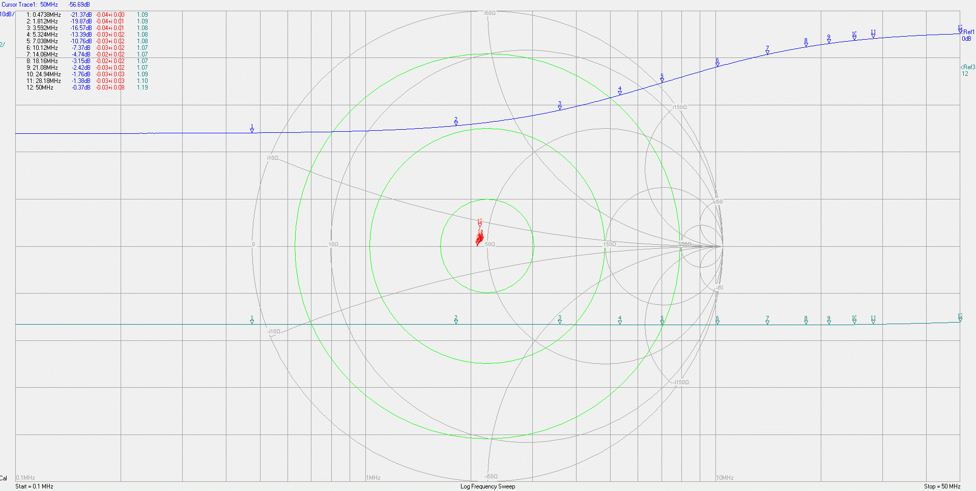
Figure 5, below, shows the typical response of the sections:

Figure 5:
The response of one of the sections as measured on a DG8SAQ VNA.
Click on the image for a larger version.

Because it can be a bit difficult to read, the values of attenuation and VSWR in the upper-left corner are reproduced below:

Frequency (MHz) Insertion Loss (db) VSWR
0.474 21.4 1.09
1.812 19.9 1.09
3.592 16.6 1.08
5.324 13.4 1.08
7.038 10.8 1.08
10.12 7.4 1.07
14.06 4.7 1.07
18.16 3.2 1.07
21.08 2.4 1.07
24.94 1.8 1.09
28.18 1.4 1.10
50.0 0.4 1.19
Figure 6:
Attenuation and VSWR of the network at amateur band frequencies.
 
Practical usage:
 
For large, broadband antennas and small, active E-field whip antennas, the tendency will be for a relatively "flat" frequency response - but with a small E-field whip antenna, the typical high-frequency roll-off can exacerbate the aforementioned low-HF band overload issue, making a filter network such as the above, even more indispensable.  While an attenuation value of about 17dB at 80 meters may seem to be rather extreme, unless your antenna system has severe low-frequency roll-off at the low end, the noise floor on 80 meters - even during a quiet winter day when the band is dead - should be at least several dB above the receiver's noise floor.

 For specifics relating to a wideband direct-sampling SDR like the KiwiSDR or Red Pitaya, refer to the earlier article linked above - "A Limited Attenuation High Pass Filter".


Set-up:

As mentioned above, a direct-sampling receiver like the KiwiSDR does not have enough sensitivity to "hear" the 10 meter quiet band noise floor at a very quiet receive site. In terms of overall system gain adjustment, a few comments are warranted:
  • A good test is to see if, on 10 meters when it is "dead", you are hearing your local noise floor.  Note the S-meter with the antenna connected and disconnected - preferably, with the input to the receive system terminated with a 50 ohm load when disconnected.  If you do not see an increase in the S-meter reading and on the waterfall by 3-5 dB, the overall system gain is too low to allow the receiver to see the noise floor at your antenna system.
  • If you do not see an increase in noise when the receiver is connected to an antenna, a bit of extra gain is recommended.  Given an ideal isotropic antenna at a very quiet receive site, it will probably take about 12 dB of gain to comfortably "see" the antenna's noise floor - assuming no other losses (coax, splitter, etc.)
  • The preferred location of an amplifier is after the filter described above as it, too, will be protected against the very strong lower-frequency HF signals - even though a device like the above will increase the loss (and noise figure) by about 1.4dB at 10 meters.
  • In cases where there are splitting losses (e.g. feeding multiple receivers) it may be beneficial to split the gain.  A modest-gain amplifier (10-14dB) might precede the splitters - the modest gain being enough to overcome splitting losses and to maintain system noise figure.
  • In the case of a low noise level receive site, the splitting losses may put the 10 meter noise floor below the detection threshold of the receiver and, if necessary, another amplifier may be placed just after the filter described above to make up for it.
  • It's worth noting that if you can detect a 3-5dB increase in noise floor with the antenna connected (versus disconnected) on every band, then even more gain will NOT further-improve system performance:  On the contrary, more gain than necessary will increase the probability of receiver overload - particularly on a direct-sampled SDR that has no AGC in its signal path like the KiwiSDR.  If one has more than 3-5dB of noise floor increase with the antenna connected on 10 meters when it is quiet, it's suggested that several dB of attenuation be added.  The preferred place to add this attenuation is in front of the amplifier to maximize its strong-signal handling - but only if one can still detect the noise floor on the antenna after doing so.  If one has a very high gain amplifier (say 20-25dB) and the gain is excessive, judicious addition of attenuation on both the input and output of the amplifier may be required.
  • When an amplifier is to be considered for HF use, it should have clearly-defined ratings - one of the most important of these is the output power capability (often "P1dB" which is the output power at 1dB compression) which, for a modestly good amplifier capable of handling strong, off-air signals, should be in excess of +20dBm.  Second to this would be the 3rd order intercept point, which should be stated as being in excess of +30dBm - and the higher the better.  Both of these parameters are indicative of how well an amplifier might deal with multiple, strong signals that may be present at the antenna without adding significant distortion of its own.
  • If you wish to pick your own frequency and impedance, the following will get you "close enough".  At the point where a single section of this circuit (as depicted in Figure 1) has an attenuation of about 4.1dB, the reactance of the "L1" and "C1" components will be equal to the desired characteristic impedance of the circuit - which will also be the same as "R2" and "R3".  Unfortunately, other parameters (e.g. the amount of attenuation at a specific frequency) are not predicted by this formula, although it's worth noting that both C1 and L1 will disappear at extremes in frequency and the circuit effectively turns into a resistive attenuator.  For example, C1 disappears (goes to infinity ohms) and L1 goes to zero ohms at DC while L1 disappears (equivalent resistance goes to infinity) and and C1 goes to zero at infinity MHz and one can pretend that these particular components no longer exist (e.g. either a short or open as appropriate).
Addendum:  Comments about the RX-888 (Mk2)
 
The RX-888 (Mk2) is a USB3-interfaced "signal acquisition device" - or an SDR front-end.  Unlike the aforementioned KiwiSDR, it has no signal processing capability at all - it's (more or less) just an A/D converter connected to a USB3 interface.  As such, it can operate at a sample rate of 130 MHz which means that it can acquire the entire HF+6 meter spectrum.  For various reasons (see the link below) it is usually better to operate an RX-888 at around 65 MHz, making it still-useful for inhaling the entire HF spectrum.
 
The RX-888 (Mk2) includes an attenuator (based on the PE4312) and a programmable-gain amplifier (using the AD8370) and this combination means that the noise figure PRIOR to the A/D converter will be on the order of 12 dB or so when the AD8370 is set for the "optimal" gain of about 20 dB:  See the link about signal dynamics of the RX-888 for a better explanation.  Unfortunately, the limiting factor - even with the AD8370 set for maximum gain - is the intrinsic noise of the A/D converter itself more than the components preceding it in the signal path.
 
In this case, I would make the following recommendation:
  • As close to the antenna as practical, place a 10-12 dB gain, low-noise RF amplifier.  This amplifier will be the primary setting for the receive system noise figure and it should have excellent signal-handling properties.
  • The "high pass filter" described above would be placed following the first amplifier.
  • Following the filter, an additional 10-12 dB gain amplifier.  As the attenuation of the filter is relatively low at the frequencies where it really matters (e.g. >20 MHz) the noise figure of the receive system is preserved for these frequencies.  Placing the second amplifier downstream also reduces the total signal power that this amplifier will "see" from lower HF frequencies.  This amplifier should be chosen to have particularly handling of strong signals.
In the case of the RX-888, the PE4312 attenuator is likely not going to be required under any normal circumstances and should be set to "zero" and any attenuation that is needed would be set using the AD8370 amplifier.

Commercially-available version of this filter

Since this article was originally written, Turn Island Systems has produced a commercially-available version of this filter (referred to as the "shelving filter") that includes a 30 MHz low-pass filter - and you may find that here:
This is also available from TAPR as a kit that includes an improved heat-sinking pad:
  • External clock kit and thermal pad:  https://tapr.org/product/rx888-clock-kit-and-thermal-pad/
 
asdf

Pages related to the RX-888:
  • Improving the thermal management of the RX-888 (Mk2) - Link
  • Measuring signal dynamics of the RX-888 (Mk2) - Link
 
This page stolen from ka7oei.blogspot.com

[End]