Showing posts with label monitor. Show all posts

Saturday, August 15, 2026

The Morrow CM-1 receiver - A relic of the cold war's effect on amateur radio

Figure 1:
The front panel of the Morrow CM-1 CONELRAD monitor.
The meter indicates relative signal strength and below it is the
on/off/volume control.  The dial - with a pair of "CD"
markings, is a smooth-tuning reduction drive - which is also
very accurate.  Shown here, it's on and tuned to a local station.
Click on the image for a larger version.

If you were an amateur (Ham) radio operator in the late 1950s and early 1960s, you  had a broadcast radio turned on in the background whenever you were on the air - or at least you should have!

The reason for this was spelled out in the FCC rules:  Beginning January 1, 1957, Section 12.192 required all amateur radio stations to monitor a broadcast station - at a minimum of ten minute intervals - to see if it transmitting, while they (the amateur) was on the air.  If the station had gone off the air, it was then required that the amateur determine if this was because of a CONELRAD alert - and if so, immediately cease transmitting.

What was CONELRAD?

CONELRAD, short for "CONtrol of ELectromagnetic RADiation", was a system - part of the U.S. Civil Defense - where, if an imminent attack of Soviet bombers was detected, ALL radio stations - commercial (AM , FM and TV) and amateur - were to go off the air to prevent their signals from being used as directional signals for navigation by the enemy.  The exception to this was that some of the AM broadcast stations were to ultimately occupy either 640 or 1240 kHz - but only for a few minutes at a time, the frequencies to be used by several different stations during that period - in a "round-robin" sort of system.  The "musical chairs" of transmitters, frequencies and locations was intended to make it difficult for the Soviet bomber to use them for navigation.

If you have seen an AM broadcast receiver intended for the U.S. market from the time period when the CONELRAD system was in existence (from about 1951 to 1963) you may have noted that at 640 and 1240 kHz there are triangular marks - often with the letters "CD" in them (the Civil Defense logo) - on the dial signifying the two CONELRAD frequencies - and these symbols are clearly visible on the tuning dial in Figure 1.  The intent of this is that civilians would tune to those frequencies to receive civil defense instructions during the "on" periods of the broadcast station near them.

Figure 2:
Rear of the CM-1.  The terminals connect to normally-open
contacts of the relay (if fitted) and the wire antenna can be
seen emerging from the chassis.  Between the two is a
potentiometer for adjusting the S-meter and relay sensitivity.
Click on the image for a larger version.

How it worked

As you might imagine, this system was cumbersome.  All stations had to be alerted in some way and "key" stations - perhaps notified via a wire service - would turn their transmitters off-on-off and on again in five second intervals and then transmit a 1 kHz tone for 15 seconds:  As transmitters of the day weren't designed to be "short-cycled" in this way, it was hard on the equipment - sometimes leading to failures.  There was also the requirement that some transmitters - and their antenna systems - change from their normal frequency to either the 640 kHz or 1240 kHz CONELRAD channel - a further complication - to participate in the on/off "round robin".

Needless to say, this system had several well-publicized false alarms as well as failures when tested over the years that it was extant.  Eventually, because of the implementation of ballistic missiles rather than piloted bombers, its reason for existing ceased in 1963.

How it affected amateur radio operators

As noted earlier, if you were an amateur radio operator, you were required to monitor a local broadcast station, while you were on the air, at least every ten minutes:  If the radio station went off the air, the idea was that you were to check for a CONELRAD alert and if it was happening, immediately stop transmitting.

Figure 3:
Top of CM-1 chassis as seen from its left side.  In the fore-
ground is the tuning capacitor, IF transformers and amplifier
tube and main filter capacitor.  The 6C4, if installed, would
be plugged in the empty socket just visible behind the tuning
capacitor.  It's well laid-out - even the audio transformer is at
an angle to minimize coupling to the AC power transformer.
The antenna wire is lightly coupled to the preselector circuit.
Click on the image for a larger version.
It's difficult to know these days how well the average amateur radio operator adhered to this rule, and for those that did, doing so certainly added a bit of complexity and awkwardness to their operating style.  A number of article appeared in the amateur radio magazines at the time describing how to "automate" the detection of the local radio station going off the air - typically by monitoring the AGC voltage of an inexpensive radio and sounding a buzzer or turning on a light.

There were also some receivers designed for just this purpose.

The Morrow Radio Mfg. CM-1

The Morrow CM-1 was one such receiver.  The receiver pictured was found among the effects of a good friend - and fellow amateur radio operator - that passed away several years ago, sitting dusty on a shelf in his basement.  After careful inspection, I was surprised to see that it had no bad capacitors:  The components used in its construction - particularly the capacitors - are all good-quality Cornell Dubilier (all are ceramic disk types other than the main filter) - and they seemed to be a cut above those found in a typical, cheap domestic radio of the time and it worked perfectly the first time it was turned on - and I haven't even bothered checking the tubes!  Even the main electrolytic filter capacitors are still in excellent shape - likely a result of the receiver having spent the past six-plus decades in a cool, dry basement.

Figure 4:
Schematic of the Morrow CM-1.  Despite the somewhat unusual tube line-up, it functions
the same as a typical "All American Five" superheterodyne receiver of the era, complete
with a 455 kHz IF.  The main difference is that it has provisions for connecting to an external
alarm or light based on the presence/absence of a signal using the (optional) 6C4 tube and the relay.
Click on the image for a larger version.

A "brief" circuit description 
(Refer to Figure 4)
 
While many "AA5" receivers use a resonant loop - either a ferrite stick or a coil wound on the back panel of the chassis for an antenna - the CM-1 uses just a short piece of wire, depicted in the upper-left corner of the diagram connected to C1, one half of the tuning capacitor and inductor "L1".  This and the 50-100pF series capacitor "lightly" couple a short piece of wire to the resonant circuit.  This works, but its effects can be swamped if a long piece of wire (more than a few feet/meters) is used which can spoil image rejection an cause the radio to overload on strong signals.

The 6EA6 converter doubles as both the local oscillator - its frequency determined by the other half of the tuning capacitor C2 and L2 - and mixer as it converts and amplifies the received signal to the Intermediate Frequency (IF) of 455 kHz via its plate through transformer T1 which forms a selective band-pass filter.  Following T1 is a 6BJ6 which functions as an amplifier at 455 kHz and this goes to T2, another 455 kHz IF transformer, and then to the 6AV6 diode/detector/amplifier tube.
 
The secondary output of transformer T2 applies the 455 kHz signal to a diode section and since its cathode is grounded, it causes that part of the transformer to go negative with the rectified DC voltage as well as the detected audio:  The received audio is then coupled via a 0.01uF capacitor and 10 MegOhm potentiometer to the triode section of this tube for amplification where the audio is then coupled to the plate of the 6AS5 - its grid biased slightly negative by the 220 Ohm resistor in the cathode - and amplified.  Functioning as a "Class A" single-ended audio amplifier, transformer T3 couples its high-impedance plate to the low-impedance speaker.

Referring back to the bottom of the secondary of T2 where the audio is tapped, the negative DC voltage that is also produced there is in proportion to the amount of signal getting to the 6AV6 detector tube and ultimately, the strength of the signal to which the radio is tuned.  This voltage is smoothed to remove the 455 kHz IF by a 250pF capacitor and then sent to one of the grids of the 6EA6 converter tube through the antenna-tuning inductor, L1 and also to one of the grids of the 6JB6 IF amplifier via the secondary of T1 and when the voltage gets more negative, its sensitivity is reduced.  In this way the "AVC" (Automatic Volume Control) is formed so that both weak and strong stations produce similar amounts of audio.

This same AVC voltage is also sent to the (optional) 6C4 tube:  If this voltage is very negative - as it would be with a moderately strong signal - this tube is "cut off", but if the signal disappears and the AVC voltage is less negative, it will conduct and thus turn on the (optional) relay.

For the signal level meter, a voltage divider using a 15k resistor  and 2k potentiometer (seen at the bottom of T1) sets the voltage threshold on one side of the 1 mA meter - the other side of which is connected to the cathode of the 6JB6 IF amplifier tube along with a 1k resistor to ground.  There are two mechanisms of action here for driving the meter:  If there is more signal into this tube, it conducts more current and the voltage goes up across the 1k resistor, but a higher signal will also result in a more negative AVC voltage which will negatively bias the tube and reduce the current.  It's this latter aspect that prevails:  A more-negative AVC will reduce the tube's conduction and also the voltage across the 1k resistor and when this voltage is lower than that across the 15k-2k voltage divider, the meter will move up-scale.
 
The final section is the power supply which consists of a transformer to isolate the circuit from the mains.  The high voltage is half-wave rectified by a "modern" (for the time) selenium diode and then filtered by one section of a two-part capacitor which is then decoupled by a 750 ohm resistor in series which then goes to another capacitor.  In this way, the voltage is reduced somewhat and better-filtered than it would be with just a single stage of smoothing. 

The CM-1 is a compact, tube (valve) type superheterodyne receiver from this time period that was designed to indicate when a station went off the air.  As can be seen from the photo, it looks more like a piece of ham gear than the AM broadcast band receiver in that it has a "nicer" geared (and accurate) tuning dial and a meter than indicates the relative strength of the signal to which it is tuned.

Internally, he CM-1 itself is mostly an unremarkable receiver:  Electrically, it's a variant of the "All American Five" (AA5) superhet that was produced by the millions over about four decades, but with a few interesting differences.  Sporting a power transformer, all of the tubes use six volt filaments and with the isolation, it - unlike most later, cheaper versions of the "AA5" - it does not have a "hot" chassis (e.g. one that is connected to one side of the line cord) - but with a solid-state (selenium) rectifier rather than the typical 35W4 and a rather different six volt tube line-up than a typical AA5.  A 6BE6 as the converter, 6BJ6 as the IF amplifier, 6AV6 as the detector/amp and interestingly, a 6AS5 (a tube typically used in car radios) for the audio output.  As can just be seen in Figure 5, the 6AS5's "getter" shows discoloration and Figure 3 reveals that there is a slight stain around the audio transformer where some of its wax wicked onto the chassis due to heat, both indicating that this receiver has quite a few "on" hours!

An interesting departure from a typical AA5 is its antenna connection.  Most AA5s had either a ferrite loopstick or a large coil of wire wound on the cardboard/masonite/phenolic back cover of the receiver that doubled as an RF pre-selector, but this receiver simply has a piece of wire capactively coupled to the tuning network connected to one of the capacitor's gangs.

According to the manual, only 2-3 feet (50-95cm) of wire is necessary for reception and testing of this CM-1 indicated that this was true - but it also means that one must resist the temptation to connect it to a longer wire:  Doing so simply overloads the receiver and wrecks image rejection, particularly since the front-end preselector tuning is overcoupled to the antenna itself, effectively bypassing it altogether

I suspect that having a really sensitive receiver was not required in this application.  When monitoring for CONELRAD, one would probably use a local station with a strong signal:  Doing so would not only help with the fact that many AM broadcast stations had to reduce their power at night, but a weak/distant station would be interfered with with the onset of nightly skywave propagation which could, at times, cause signal levels to fluctuate wildly, resulting in false alarms.

During testing - with only the 2' (50cm) wire antenna - when placed outside, I found that the receiver was capable of picking up even the weaker signals across the broadcast band, but since it is a wire rather than a coil, it's non-directional and is far more prone to pick up local "E-field" noise energy than the typical "H-field" loop which is not only directional, but offers a degree of rejection of such noise.  Practically speaking, one could probably add a loop antenna, connecting to the wire and the grounded screw (one of the two used for the relay) on the back panel to improve reception in today's modern electrical environment.

Figure 5:
The other side of the top of the chassis.  In the foreground is
the power transformer and next to it is the 6AS5 audio amp.
The socket next to the 6AS5 is for the (optional) relay, driven
by the (also optional) 6C4.  The antenna tuning coil is visible
next to the tuning capacitor, almost against the front panel.
Click on the image for a larger version.

When I first removed the receiver from its chassis I thought that it was missing two tubes as evidenced by empty sockets, but I then realized that it had a selenium rectifier accounting for there being only four tubes and immediately wondered why there were two extra sockets.  A bit of "Google-Fu" found the manual online and I learned why:   This receiver could optionally be fitted with a relay in one of the sockets (this also required another tube - a 6C4 to detect the loss of signal and drive the relay) that was intended to operate a sounder, a light or some other means of indicating loss of signal.  I find it interesting that this relay and its driver tube were omitted as shipped from the manufacturer, but I suspect that this was a cost-saving measure - and it may have been enough for most amateur radio operators using this receiver to simply glance at the front-panel meter occasionally to see if a signal was still there.

Is it still useful?

The reason raison d'etre for this device ceased to be when, in 1963, the FCC rule requiring the amateur radio operator to monitor broadcast stations while operating was rescinded and removed from FCC Section 12.192, but since it's rather compact and has a speaker that dominates the top of the case means that it still works as a pretty nice AM broadcast receiver.  Whether or not one might think an AM-only receiver is still useful overall is another matter altogether!

Figure 6:
Bottom of chassis of the CM-1.  High-quality components -
including all Cornell Dubilier capacitors - are used
throughout.  The orange object left of center is the selenium
rectifier and the oscillator coil is just right of center.
Click on the image for a larger version.
The usefulness and practicality of this receiver is probably on par with most other vintage radios that one might collect and own:  They are not likely to be "everyday drivers" and more likely to sit on a shelf with other old radios - but this one, at least, has a particularly interesting bit of cold-war history behind its existence.

* * * * * * *

 This page stolen from ka7oei.blogspot.com

[END]

Sunday, June 7, 2020

An ESP8266-based Temperature, Humidity and Line Voltage monitor

Figure 1:
The completed Temperature/Humidity/Line Voltage web
server/telemetering device.  The remote temperature/humidity
sensor is the unit to the left.  The two AC-DC wall adapters used for
powering the unit and monitoring mains voltage are not visible.
Click on the image for a larger version.
As anyone who reads this blog probably knows, I have a bit to do with the operation and maintenance of the Northern Utah WebSDR - a remote receiver system that allows anyone with Internet access and a web browser to listen to the LF, MF, HF and some of the VHF bands as heard from a rural site in Northern Utah.  The equipment for this receiver system is located a small building in the middle of mosquito and deer-fly infested range land near brackish marshes - no-where that anyone in their right mind would like to be during most of the year.  With the normal weather in the summer and many clear days, this building gets hot at times:  It's been observed to exceed 130F (55C) on the hottest days inside - a temperature that causes the fans on the computers scream!

Even though electronic equipment is best kept at much lower temperatures, this isn't practical in this building as it would be prohibitively expensive to run the on-site air conditioner full time - but all we really need to do is to keep the building closer to the outside temperature and even though it may be uncomfortable for humans, it is enough to keep the electronics happy.  To that end, vents have recently been installed to allow convection to pull away most of the heat and the exterior will soon been painted with white "RV" paint to (hopefully) reduce the heating effects of direct sun.

It would make sense, then, that we had a way to remotely monitor the building's internal temperature as a means of monitoring the situation.  Additionally, temperature information can also be used to make minor adjustments to the frequencies of some of the receivers' local oscillators to help counter thermal drift.

Figure 2:
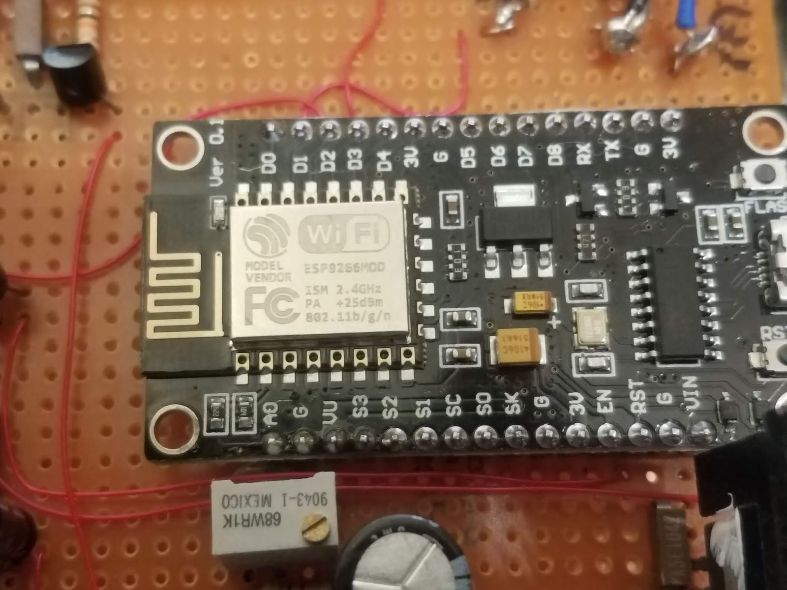
The "business end" of the small board that contains the
ESP8266 module - the device with the metal shield.
This board also includes a USB plug, a CH340-like
USB to serial converter that allows for programming
and debugging and a voltage regulator that allows direct
operation of this board from a 5 volt supply.
As can be seen here and in Figure 4, the ESP8266 board was,
itself, mounted to a larger prototyping board for construction
of the ancillary circuitry.
Click on the image for a larger version.
On site we do have an Ambient Weather (tm) station, but anyone who has used this (or similar) hardware knows that some vendors of this type of gear make it difficult to obtain your own data without jumping through hoops:  Although this data is visually available on the local display or even on a web site, it is a bit awkward to pull this data from their system and (at least with the newer versions of the hardware) one cannot get this data locally from the weather station itself.

Fortunately, the most-needed data - temperature inside the building - is easily measured using inexpensive sensors, so it made sense to throw together a device that could make these measurements and present them in an easy-to-use web interface.

The ESP8266 "Arduino" board:

As is often the case with projects like this, the Internet has the answer.  The ESP8266 is an inexpensive embedded computer module that has a reasonable amount of program memory and RAM and it also sports hardware such as a WiFi module, several digital  I/O pins and a 10 bit A/D converter.  What this means is that for less than U.S.$12 you can get two of these delivered to your doorstep that contain an already-mounted ESP8266 module on a carrier board with a USB port in a format that strongly resembles that of the ubiquitous Arduino development board.  More importantly, the Arduino IDE supports this board meaning that it is pretty easy to use this hardware in your own projects.

Because the '8266 board has been available for quite a while, there is a large library of software for it - including a small web server and code to interface with many types of devices, including the well-known (and relatively inexpensive) DHT-22 temperature and humidity sensor.

Comment:  The ESP8266 variant used here appears to be the "12E" version which has 32 Mbit (4 Mbytes) of Flash memory and "around 50k" of RAM.

The "DHT Humidity and Temperature web server":

It took only a few minutes to find online several implementations of a web server coupled with the DHT-22 sensor - and I chose what seemed to be a popular version on a web site by Rui Santos - to look at it yourself, go here:

randomnerdtutorials.com/esp8266-dht11dht22-temperature-and-humidity-web-server-with-arduino-ide/

Presented in good detail, it was only about 20 minutes from the start to tack a few flying leads to my $6 ESP8266 "Arduino" board to connect the DHT-22 sensor before I had a wireless web server on my workbench that was happily reading the temperature and humidity.

Of course, getting something working can be miles from a finished project and that was certainly the case here as the project was about to be subject to self-inflicted feature creep and code bloat as I'd already decided that I wanted it to do two other things as well:
  • Monitor the AC line voltage.  The WebSDR receive site - being rural - suffers from very dirty AC mains power.  We have seen the nominal 120 volt mains exceed 140 volts for brief periods in addition to the frequent outages - and it would be nice to have a device that would allow us to record such excursions.
  • Telemeter the gathered information via RF.  Because the ESP8266 is a small computer - and it has data that we want - and we are at a radio receive site - it would be a simple matter to have this unit tap out the information using Morse code on a low-power, unlicensed (part 15) transmitter that was capable of being received by the on-site receivers.
The final result is this, in schematic form:
Figure 3:
The schematic of the support circuitry of the ESP8266 unit described, including a pictorial representation of the processor board itself.
Click on the image for a larger version.
Circuit description:

The ESP8266 is treated as a single component - the support circuit being connected to the pins as noted with the '8266 itself being mounted on a larger board as can be seen in Figure 4, below.  It's worth noting that this is a 3.3 volt device which means that the "high" output voltage is around 3 volts:  If I'd needed a digital input, I would have had to make sure that the logic high input level was appropriately limited in voltage.

Power supply and monitoring:

There are two uneregulated AC-DC transformer "wall warts", both being a low-voltage transformer (9-12 volts AC) with full-wave rectification and capacitive filtering  - one to power the unit and the other to monitor the line voltage.  The separation of these two function is necessary for obvious reasons:  We'd want the unit to continue to function when the AC mains was out, but continue to run from the UPS which means that we can't monitor or own power supply!  Even if we could, the current consumption of the unit varies a bit and as a consequence, so does the unregulated voltage from the monitor supply.  The source of power for the unit itself could be anything that can provide 10-15 volts DC - regulated or not - but these AC->DC transformers were on-hand, plus being simple transformer-rectifier-filter units, they do not generate RF noise - unlike some switching-type devices - a factor important at a radio receive site.

The power from each of the AC-DC adapters enter via a screw terminal strip and immediately passes through a pair of bifilar-wound inductors - the purpose here being to provide RF isolation:  Because this device contains a computer and a low-power transmitter, we don't want any signals on this device from being radiated on the power leads.

The first AC-DC adapter is used to power the unit - a red LED indicating that voltage is present.  Following this is a "bog standard" 5 volt regulator using a 7805 to provide a lower voltage to feed to the "VIN" pin of the ESP8266 board and to run other circuitry on board.

The other wall wart has only a light load - most of the current being consumed by D4, an orange LED used to indicate that the mains voltage being monitored is present.  As you would expect, an unregulated AC-DC supply like this isn't a precision instrument when it comes to measuring line voltage as it is not any sort of RMS measuring device and with its built-in filter capacitor, it's also relatively slow to respond  - but it is "good enough" for the task at hand.

This voltage is divided down via R3 and variable resistor R4 for the 0-3.3 volt input range of the "A0" (analog input) pin on the ESP8266 module.  (Note:  It's reported that A/D range of the "raw" '8266 module is 0-1 volt - apparently this board includes a voltage divider to scale from 3.3 volts.)  Resistor R4 is 10 turn unit used for calibration of the line voltage.

Watchdog timer:

Figure 4:
The completed ESP8266-based temperature, humidity and line voltage
monitoring device.  The CW transmitter portion is in the upper-left corner
of the board with the 555-based watchdog timer below it.  In the lower-
right corner is the 7805 regulator with its heat sink with R4, the
calibration for the line voltage being seen just below the lower-left
corner of the ESP8266 board.  The gray wire at the top connects to the
small board containing the DHT-22 temperature/humidity sensor.
The entire unit is mounted via stand-offs into the lid of the plastic case
depicted in Figure 1.  Inside the lid I placed a sheet of self-adhesive
copper foil that is used as a ground plane to which the input filter
capacitors (C1, C3), the LEDs and the ground connections of the
board are soldered.
Click on the image for a larger version.
Because this device is unattended in a remote location I took the precaution of adding a simple hardware watchdog timer.  The software generates a pulse train (nominally a square wave) on pin "D2" which is then applied to transistor Q1:  Capacitive coupling, via C7, is used as a DC coupled signal would have made it possible that a watchdog reset condition could have been simulated if the pin were stuck "high".  The timer itself is the ubiquitous NE555 "programmed" via C8 and R7/R8 to have an approximately 45 second period.

The pulse train from pin D2 pulses Q1, keeping timing capacitor C8 discharged - but if the pulse train stops, pin 3 will go high after the timing period, briefly pulsing the "RST" (reset) pin of the EP8266 via capacitively-coupled Q2.  A 45 second period was chosen as it takes about 8 seconds for the ESP8266 to "boot up" enough for the software to generate the - and it also allows just enough time to upload the program.

During initial development one would probably not plug a 555 into its IC socket as spurious resets would likely be an annoyance as there may not be code to create the reset pulses, but with the size of the code for this project the reset period is long enough to allow uploading of the code before a reset occurs and the pulses resume.

Temperature/Humidity sensor:

The readily-available DHT-22 sensor is used, chosen over the slightly cheaper DHT-11 as the '22 offers a wider temperature and humidity measurement range - although the software can be configured to work with either one. To avoid erroneous temperature or humidity measurements from the unit's heat generation, this sensor is mounted on its own board as depicted in Figure 3.  On this small board is not only a power supply bypass capacitor (C20) but also a pull-up resistor R19.

The "sensor module" - visible in Figure 1 - was placed inside a small piece of ABS tubing (gray non-metallic electrical conduit) for protection with small pieces of nylon window screen glued to each end to keep out insects, but allow air flow to permit accurate measurements.

CW transmitter:

Because it is a computer - and there was plenty of code space - I decided to add Morse Code generation to provide telemetry that could be picked up by the HF receivers on site.  Stealing my own Morse-generating C code from a 20+ year old PIC project, I made minor modifications to it, using a hardware-derived timer in the main loop to provide a sending clock.  The Morse generating code toggles D3, setting it high to "key" the transmitter.

The signal from pin D3 goes to Q3 which is wired via current-limiting resistor R13 to Q4, a PNP transistor to provide "high side" keying of the unregulated V+ supply.  This voltage is then passed through resistor R14 which provides both a bit of current limiting and, with C12, some R/C filtering to slow the rise/fall of the voltage:  Without it the RF would have been keyed very "hard" causing objectionable "key clicks" on the rise and fall of the RF waveform.  This voltage is used to key both the buffer and the output amplifiers, described below.

The signal source is a 28.57 MHz crystal "can" oscillator module that I found in my junk box.  While I could, in theory, have done CW keying by turning this oscillator on and off, these oscillators aren't designed to be particularly stable and doing so would have caused the oscillator to "chirp" - that is, the short-term frequency drift that occurred when power was applied would have caused an objectionable shift in the received audio tone during keying.

Instead, the oscillator was powered continuously with its output fed to Q5, an emitter-follower buffer:  R15 "decouples" the oscillator from Q5 somewhat and without it, the RF current into the base of Q5 would increase when its collector voltage was switched off causing the oscillator to heat internally, resulting in a frequency shift.  The output of the buffer circuit is then passed via resistive and capacitive coupling to Q6 which is used as the final RF amplifier.  L1 is used to decouple its collector from the power supply while C16 removes the DC voltage from the RF output.  The remaining components - C17-C19 and L2/L3 comprise a low-pass filter resulting in harmonics that are at least 40dB below the fundamental.

This circuit was originally built without Q5, the buffer amplifier, but I had two issues that could only be resolved by its addition:
  • Backwave.  Because the oscillator runs continuously, there will inevitably be a bit of leakage - and in CW where it is the very presence and absence of the signal that is used to convey the information, having a rather strong signal when there is supposed to be silence made it difficult to "copy" the code.  When Q6 was turned off, there was enough leakage between its base and collector to offer only about 15 dB of attenuation when the transmitter was "un keyed".
  • Oscillator stability.  As noted above, R15 was used on Q5 to limit the current out of the oscillator to prevent frequency drift as buffer transistor Q5 was keyed.  When I'd tried to drive the output (Q6) directly - without a buffer - I had the same problem:  If I coupled enough energy to drive the transistor, the frequency would vary with the CW keying - and the backwave would get worse - but if I increased the resistor enough to reduce the problem, the transistor would be properly driven - which also increased the backwave as the transistor's output would fall in comparison to the signal leakage.
With the circuit built as shown the backwave is at least 40dB below the keyed output  - which is more than adequate for the task.

The code:

As noted above, the basis of the project was that published by Rui Santos - and in the spirit of open source, the code was modified:
  • The original code included some small graphics served on the web page - but in line with the KISS principle, this was stripped out in favor of the simplest text, using only standard HTML formatting.
  • Additional code was added to read the AC mains voltage via pin "A0".  In the main "loop" routine, this input is read 100 times a second and then averaged, with a new reading made available every second.  This average removes most of the noise on the pin - some of which is internal to the '8266 itself, but the majority of which is due to a small amount of AC ripple on the voltage monitoring line.
  • Additional code was added to record the minimum and maximum of all of the monitor parameters - that is, temperature, humidity and line voltage.
  • The default of the code was to read the temperature in Celsius, but being in the U.S. I added code to give the readings in Fahrenheit as well. 
  • The web server code was modified to display all of the available data - the temperature in Fahrenheit and Celsius, the humidity and line voltage - and their minimum and maximum values.
  • Addition modification was made to the web server code to allow each of the data points to be read in simple text format to simplify parsing for remote monitoring and logging of this data.  The nature of the the web server actually made it very easy!
  • Yet another modification was made to reset the minimum and maximum readings and to provide information as to how many seconds it had been since a reset had occurred.  The temperature/humidity min/max reset is separate from the line voltage min/max.
  • The code also keeps track of mains voltage that falls below a threshold (an outage) or exceeds a threshold (a "surge") - both of which are extremely common at the remote receive site. 
  • I added my own Morse generation code, ported from some PIC-based "C" code that I wrote about 25 years ago and interfaced it with the main timing loop.

Source Code:

If you are interested in the source code (sketch) you may find it at THIS LINK.

A few minor changes/improvements - noted in the source code's header - have been made since the original posting.

Implementation:

Figure 5:
 A screen shot of the web page.  This same information is available
from individual links (on the bottom half of the page) that will
return just the information requested, making it trivial to obtain
individual data points using something like WGET.
Click on the image for a larger version.


As mentioned, with the WiFi capability of the ESP8266, the information that this device records is available via a web page on the wireless network:  One only need enter the SSID and wireless password at compile time.  For reasons obvious to anyone familiar with the Internet, this device won't be accessible from the web itself, but only to devices on the local network.

With the CW generator operating on 28.57 MHz, this signal lands within the 10 meter amateur band - and with this device being co-sited with receivers, it is a simple matter of tuning to that frequency to hear the telemetry.  Even though the RF output power is on the order of 50 milliwatts, the actual transmit "antenna" is a very small piece of wire - large enough to radiate just enough signal to be heard via the nearby antennas but not nearly enough to exceed FCC part 15 rules, eliminating the need for this device to transmit an FCC-issued callsign.

Comment:

This device was installed at the Northern Utah WebSDR shortly after this article was originally posted.  You may hear the Morse portion of this device via this link


This page stolen from ka7oei.blogspot.com

[END]