Showing posts with label matching. Show all posts

Wednesday, February 25, 2026

Impedance matching (auto) transformer and common-mode choke for the JPC-7 dipole and other electrically-short (loaded) dipoles and verticals

Figure 1:
The JPC-7 loaded dipole out in the wild!
Click on the image for a larger version.

Loading coils and "electrically-short" antennas

It is well-known that you can make a "short" wire (e.g. one that is significantly shorter than 1/4 wavelength at the operating frequency) resonant by putting in series with it a coil.  There is no "magic" in this as the inductance of the coil, appropriately chosen, can completely cancel out the capacitance of the electrically-short wire, result being that at "resonance" we are left only with a pure resistance.

In an ideal situation, what we would be left with would be just the radiation resistance of this antenna and for such an antenna, this would mean that the feedpoint resistance would be less than 50 Ohms - probably much less!  In reality, the feedpoint resistance would really a combination of "ground" (counterpoise) losses, conductor losses of the antenna, and losses of the coil itself.

What this means is that if you have an electrically short antenna such as a loaded dipole or vertical with only a series loading coil tuned to resonance at the frequency of interest and no other matching scheme, its feedpoint impedance should be well under 50 Ohms on some bands if it is operating efficiently.

This is often not the case with portable antennas!

Figure 2:
The original stainless steel coil (top) for the
JPC-7 (and JPC-12) with the coil rewound with
silver-plated "jewelry" wire (bottom).
Click on the image for a larger version.

The JPC-7

Some time ago I wrote extensively about the JPC-7 (See the article, "Observations, analysis and field use of the JPC-7 portable "dipole" antenna" - LINK) where I discussed the bits and pieces comprising it:  I have used it in the field a number of times, finding it to work as advertised.

In short, this is a loaded dipole - at least on the lower amateur bands (especially 40 and 30 meters) that is intended for portable use:  On these bands (including 20 and 17 meters) it is physically shorter than 1/2 wavelength and it requires the adjustment of its series inductors to resonate.  On the higher bands (15 and above) its overall length approaches and exceeds a half wavelength meaning that it's a full-sized dipole and is (generally) tuned by adjusting the length of the telescoping sections.

Lossy coils!

There is a down-side:  As sold, it has loading coils that are wound with stainless steel:  As noted in the original article, these coils are very lossy, with MOST of the RF power being dissipated as heat on the lower bands (40 and 30 meters in particular - roughly an "S" unit of signal loss) where a fair bit of inductance is required.

Figure 3:
An example of heating of a stainless steel
loading coil on a short vertical - here, made by
Wolf River.  On 40 meters the temperature of
the coil rose by more than 30F (17C) with
60 watts of RF applied for 60 seconds.
Click on the image for a larger version.

The reason for this is that an electrically-short antenna (one that is physically short compared to the wavelength.)  The total length of the telescoping sections alone put together is about 198" (5 meters) - which is about 12.5% of a wavelength at 40 meters implies that the feedpoint resistance would, were there no loss at all, be around 8-10 Ohms, resulting in a VSWR of more than 4:1.

Calculations and measurements indicate that the approximate Ohmic loss of the original stainless-steel loading coil - if we optimistically presume it to have a Q of 47 - would be about 19 Ohms per coil (remember that there are two coils!) and the sum of the two coils would push feedpoint resistance near-ish 50 Ohms.  The result is that roughly 1 "S-unit" (about 6dB) is lost in the coils alone:  Contacts would still be made, but running a "compromised" antenna (e.g. physically small) that already would be less-efficient than its full-sized counterpart and adding another S-unit of loss doesn't sound like an optimal solution!

Using silver-plated copper "Jewelry Wire" (found on Amazon) to rewind the original loading coils dramatically improved the "Q" (approximately 200) and lowering the Ohmic loss to around 4 Ohms.  The result of this is that rather than something in the 40-50 Ohms for the feedpoint resistance, it dropped to "about 15" Ohms on 40 meters - a VSWR of around 3:1 - and even lower impedance than that (higher VSWR) when I reconfigured the antenna for 60 meters (e.g. added extra screw-together sections, moved the coils next to the feedpoint and added extra "drooping" wires to the ends of the dipole).  At the higher bands (20 meters and up) the feedpoint impedance is close enough to 50 Ohms that one can probably forego the auto transformer at all.

For more information about the "Silver-plated versus Stainless Steel" topic, see the blog entry "Rewinding the Stainless Steel coils with Silver-Plated copper wire on the JPC-7 and JPC-12 antennas" - link.

When a worse VSWR is a good thing!

The first thought when being faced with a higher VSWR on an antenna might be that it was made to be worse - but here is a instance where this is not the case.  As noted earlier, an electrically short antenna like a dipole or vertical can be made to be "longer" (from an RF standpoint) with the addition of a "loading" coil to a "short" (in terms of wavelength) antenna - but the job of the coil is to cancel out the capacitance of the, leaving only the resistive portion of the antenna's feedpoint impedance.

For a full-sized dipole or vertical, this resistance is "close enough" to 50 Ohms (perhaps 35-70 Ohms, depending on the antenna and its environment) to provide a decent load to a modern radio - even one without tuner.  But a very small antenna - where a lot more "coil" is required - will have a lower feedpoint resistance unless your coil is very lossy, as was the case with the stainless steel coils on the JPC-7.  With the lower-loss silver plated coil we (mostly) eliminate it as a lossy component - but end up with a different problem.

Figure 4:
Inside the LDG Z-11 antenna tuner.  The center
toroid shows evidence of have been heated,
apparently due to matching very low "R".
Click on the image for a larger version.

With a feedpoint resistance of 13-15 Ohms on 40 meters with the JPC-7 and silver plated coil and its resulting 3-ish:1 VSWR one can "fix" this with an antenna tuner to make the radio happy - and I have done this many times, placing the tuner (an LDG Z-11 Pro) right at the antenna (only a few feet/a meter of coax) but almost all common antenna tuners have quite high losses at these low impedances.

Testing with the cover of the tuner removed, I have noted that one ore more of its toroids in particular will run very warm with just 100 watts of power - Figure 4 shows the inside of this tuner showing one of its toroids discolored because of this.  Fortunately, iron-powder toroids are very forgiving of heating with very high Curie temperatures and other than cosmetic (e.g. discoloring the paint) moderate heating won't have any lasting effects as long as it remains intact (e.g. not cracked) and there aren't problems with (possibly-degraded) insulation between turns of the windings.

The other issue is that the balun originally supplied with the JPC-7 - intended for 50 Ohm operation - also got very warm, and after a bit more than a minute of continuous 100 watts at 40 meters the VSWR would start to rise due to its ferrite reaching the Curie temperature, causing the permeability to drop like a rock:  Essentially, the ferrite would "go away" when it got hot - likely not a problem on SSB or CW, but it might be on "key down" digital modes at full power.  This heating seemed to be more severe at the low impedances (below 20 Ohms) than at 50 Ohms.

Eliminating the tuner

By definition, we can remove the reactive component of the short antenna with the loading coil:  Its inductance will cancel out the capacitance of the antenna at resonance (which is the very definition of resonance) leaving only a pure resistance.  While an antenna tuner is able to cancel out capacitive and inductive reactance - or just pure resistance - we have a situation where, with a properly-tuned loading coil - we have only resistance and for that we don't need a tuner and we can use just a transformer, to change the impedance from whatever it is to 50 Ohms.

An easy way to do this is with an autotransformer.  This is a device with just one winding and in this case - where we are trying to tune to a feedpoint resistance lower than 50 Ohms - we can feed our power across the ends of the entire coil and tap it at various points along the winding to get our desired (lower) impedance.  For my application, having several taps between about 10 and 40 Ohms (plus the natural 50 Ohm feed impedance) would assure the ability to attain a VSWR of better than 1.5:1 for any purely resistive impedance between 7 and 75 Ohms.

The tyranny of the "electrically small antenna" and efficiency

It's worth noting several things about electrically-small low-band HF antennas - which includes portable antennas like the JPC-7, JPC-12 as well as mobile antennas - and how they interact with common antenna tuners (which an autotransformer is not):

  • Any efficient, electrically-small vertical antenna will have a very low impedance once it is resonated:  For example, a "perfect", loss-less 1.5 meter (4.9 foot) long vertical antenna system on 40 meters would have a radiation resistance of about half an Ohm.
  • Without losses due to the coils and stainless-steel telescoping rods, etc., the feedpoint resistance of the JPC-7 would, at 40 meters, be in the vicinity of 3-5 Ohms, depending on how many screw-together sections are used (e.g. the longer, the higher).
  • Any automatic (or manual) antenna tuner that you are likely to ever use for portable operation will have rather poor efficiency when trying to match at lower than 20 Ohms or so - which translates to heat as demonstrated in Figure 4.

These facts - among others - conspire against having a small, efficient mobile antenna for the lower HF bands (e.g. 80-40 meters).  In the real world, other losses (coil, antenna wire, ground) will conspire to make the feedpoint impedance much higher than the "less than an Ohm" that the would theoretically be - and any difference between the feedpoint resistance at resonance and the predicted radiation resistance is where most of the power in such an antenna system is lost:  In a typical antenna of this sort, the vast majority of transmitted power is lost in heat rather than radiated.

With significant efforts, it may be practical to get the losses of such an antenna system (which includes not just the antenna, but the series matching coil and ground losses an other factors) down to about 10 Ohms - still far above the 0.5-5 Ohms of our "perfect" antennas in the examples above - but as we know, physics conspires against us as trying to force-feed such an antenna with a tuner will probably put it into the impedance range where it is very inefficient.

It's worth noting that many simple and inexpensive mobile antennas achieve at least part of their "matching" to 50 Ohms simply by being lossy as depicted in Figure 3:  Most of the power is simply burned up in the coil.  This method is convenient in that it simplifies the problem with matching and is often accompanied by much wider tuning bandwidth (reducing the need to frequently re-tune when one changes frequency) than with our hypothetical "high efficiency" antenna, but the trade-off is poor efficiency.

Auto transformer for impedance matching 

Another way to handle this is to simply transform (pun intended!) the impedance downwards from 50 Ohms - and one way that this could be done is with a transformer of some type - and the simplest of these is one with a single winding with one or more taps, called an auto transformer.  Such transformers are commonly used to match a random wire (9:1 matching to about 450 Ohms) and for end-fed half-wave antennas (49:1 matching to about 2450 Ohms) - but we can also efficiently transform the impedance downwards.  By designing appropriately, this transformer can be made to be very efficient.

Commercial RF Auto Transformers:  The Atlas MT-1

It would seem that the use of an auto transformer for matching a low-impedance antenna - such as a low-band mobile antenna on a vehicle - used to be more common decades ago, but has fallen out of favor, possibly due to the easy and cheap availability of automatic antenna tuners:  Devices that do this function include the Atlas MT-1 (see Figure 5) and the Swan MMBX (described later), both of which have a number of low-impedance taps. 

Figure 5:
The Atlas MT-1 autotransformer,  The variety of
taps available provide the possibility of achieving a 1.5:1
match to any resistive loads between 9 and 75 Ohms.
Click on the image for a larger version.

My initial thought was to use a ferrite toroid as the core for the auto transformer.  As a general rule of thumb, a transformer should ideally have an inductive reactance of about ten times that of the operating impedance at the lowest frequency (e.g. 500 Ohms for a 50 Ohm system) but, in a pinch, just three times the operating impedance (e.g. 150 Ohms for a 50 Ohm system) was "OK".  With this in mind I wound 7 turns on an FT140-43 toroid with multiple taps.  The inductance of this arrangement was about 45uH which correlates with about 1900 Ohms at 7 MHz - well above the target inductive reactance but it would have been difficult to achieve the multiple taps needed to attain the impedance steps with fewer turns.

This transformer - wound on ferrite - did not work well at all!  When testing it on the antenna, I could not achieve a sensible match and I quickly realized that the problem was due to leakage inductance of the transformer itself.  An ideal transformer would simply transform the voltage according to the tap's turns ratio, but any practical transformer will place some amount of inductance in series with the supposedly ideal tap, and it was likely this spurious series inductance (which needed only to be a few uH to make it "un-matchable") was totally messing up the attempt to tune the antenna, departing far from the ideal transformer at RF.

Measuring the self-inductance of the Atlas MT-1 confirmed this:  Its end-to-end inductance was about 2uH and the inductances between the taps and ground - the results of these measurements made using my HP-4275A LCR Meter (at 4 and 10 MHz - interpolated at 7 MHz) are as follows:

Tap marking
(Ohms)
@ 4 MHz
Inductance uH
(XL Ohms)
@ 7 MHz (Interpolated)
Inductance uH
(XL Ohms)
@ 10 MHz
Inductance uH
(XL Ohms)
521.87uH
(46.6)
1.8uH
(79)
1.74uH
(116)
230.95uH
(24.4)
0.95uH
(41.8)
0.95uH
(61)
180.77uH
(18.1)
0.75uH
(33)
0.72uH
(47)
130.61uH
(14.3)
0.57uH
(25)
0.53uH
(35.8)

Figure 6:
The impedances (XL ) of the taps on the Atlas MT-1 auto transformer versus frequency.

While "about 2uH" of inductance at 40 meters (7 MHz) doesn't fit the "3x reactance" rule-of-thumb (e.g. it had 79 Ohms XL in a 50 Ohm system rather than around 150 Ohms XL) it will still work OK, acting as a parallel inductance across the antenna - but the important part is that there will be a fraction of the leakage inductance compared to the version with the ferrite core mentioned above:  A small amount of this inductance would lower the resonance frequency slightly, but not disastrously so.

Figure 7:
A close-up view of the MMBX matcher.
Top:  The front panel of the MMBX.
Bottom:  Inside the MMBX showing the
tapped transformer and (underneath)
the ceramic switch.
Click on the image for a larger version.

The Swan/Cubic MMBX RF Auto Transformer

A similar device is the Swan/Cubic MMBX which operates on the same principle, but uses a 7-position rotary switch to select the output impedance rather than using banana plugs like the Atlas MT-1.  Depending on the vintage, the switch is labeled with letters as A-G or as impedance levels of 50, 38, 28, 19, 12, 7 and 3 Ohms, respectively.

As seen in Figure 7, the MMBX consists of a tapped inductor wound on a pair of stacked toroidal cores (each being 1.125" O.D., 0.75" I.D. and 0.375" tall).  I've seen several of these MMBXs over the years and their construction seemed to vary slightly in the case of this unit, it's technically not an auto transformer:  

Careful inspection of Figure 7 will reveal that there are two windings - the red one connecting to the 50 Ohm side (left-hand side on the lower portion) consisting of eight turns while the other winding (the tinned wire) also consists of eight turns in parallel with taps connected to a good-quality ceramic rotary switch on every other turn.  I have seen examples of this same model where there is just a single, tapped winding which would be easier to construct and likely to be slightly more efficient (e.g. somewhat tighter coupling than one might get with two, separate windings) - but functionally identical.  In other words, this could have been built as a conventional auto transformer with one winding, so for the purpose of discussion, we'll do so.

Because of the rather low inductance value (see Figure 8) it is likely that the toroidal cores are not typical Amidon cores familiar to most amateurs due to the fact that not only are the not a standard size from their catalog.  A bit of calculation indicates that they are approximately equal to a hypothetical FT125-61 ferrite core - likely a material from a different manufacture with slightly lower permeability than the modern "61" ferrite material.

I was curious as to the inductance values used by the MMBX, and a quick test showed to be as follows:

Switch setting (approx Ohms)Nominal InductanceXL@4MHzXL@7MHzXL@10MHz
"A" (50)5.8uH146 Ohms255 Ohms364 Ohms
"B" (38)4.5uH113 Ohms198 Ohms283 Ohms
"C" (28)3.4uH84 Ohms148 Ohms211 Ohms
"D" (19)2.4uH60 Ohms105 Ohms151 Ohms
"E" (12)1.6uH40 Ohms70 Ohms100 Ohms
"F" (7)0.95uH24 Ohms42 Ohms60 Ohms
"G" (3)0.45uH11 Ohms20 Ohms28 Ohms
 
Figure 8:
The inductance values and calculated impedances (XL ) of the taps on the Cubic/Swan MMBX at various frequencies.

Figure 9:
The auto-transformer, wound on a T157-2 iron-powder
toroid with taps terminated with 2.5mm banana plugs.
Click on the image for a larger version.
Comparing the tables for Figure 6 (for the Atlas MT-1) and Figure 8 (for the MMBX) we note several things:  The inductance of the MMBX is quite a bit higher than that of the MT-1 - and at the lowest frequency of 4 MHz (close enough to 80 meters) it more or less meets the "3x rule-of-thumb" design suggestion where the inductive reactance (XL) of the entire tapped coils (e.g. auto transformer) is three times that of the operating impedance.
 
The other thing that is worth noting is that whereas the MT-1 had four impedance taps (including 50 ohms), the MMBX has seven taps.  In reality, the various impedances of the MT-1 are, as noted earlier, able to match anything between 7 and 75 Ohms (resistive) to an SWR of 1.5:1 or better, the larger number of taps on the MMBX means that one could  likely find a better match than 1.5:1 between its rated 3-50 ohms and possibly 1.5:1 down to 2 Ohms presuming that the antenna itself was tuned to be resonant (e.g. reactance tuned out).
 
Replicating the auto transformer

Rather than reinventing the wheel, I decided to (more or less) replicate the electrical properties of the MT-1 (and similar devices) and for this I chose a T157-2 Iron-powder toroid.  With a target inductance of "about" 2uH I wound 13 turns of 16AWG silver-plated PTFE (Teflon) insulated wire which should, in theory yield about 2.4uH - but when compressed together on the core it yielded about 3.6uH which correlates with about 158 Ohm at 7 MHz -  almost exactly 3x the 50 Ohm system impedance.

As can be seen in Figure 9, taps were placed at 6, 7, 8, 9 and 11 turns (from ground) by scraping the insulation off the side if the wire and tack-soldering wires to it providing impedance taps of approximately 11, 14, 19, 24, 36 Ohms - plus another wire across the 50 Ohm feed for the higher bands:  These impedances resulted from where the turns landed and it was convenient to attach taps rather than from any attempts to obtain specific or precise impedances:  After construction, I labeled the leads with the approximate impedances - for obvious reasons!

I used five taps to allow a selection of an impedance to be able to obtain about 1.25:1 VSWR or better, but if I were happy with just 1.5:1, I could have chosen fewer taps in the manner of the Atlas MT-1 discussed, above.

As the impedance of a tap is related to square relation of the number of turns (e.g. twice the number of turns results in 4x the impedance) there's a pretty simple formula to follow to calculate the impedance of a tap:

Ztap = (Zsys) / ((Turnstotal/Turnstap)2)

Where:

Ztap = Impedance of the autotransformer tap

Zsys = System impedance (typically 50 Ohms)

Turnstotal = Total number of turns on the autotransformer (13 turns in our example)

Turnstap = Number of turns from the bottom (ground) end of the autotransformer to the tap

In other words:

 Ztap = (50) / ((Turnstotal/Turnstap)2)

Taking our 13 turn autotransformer as an example, we can calculate the impedance at any turn.  Taking the 8th turn as an example:

Ztap = (50) / ((13/8)2)  therefore,

Ztap = 18.9 Ohms 

Or, if you know the desired target impedance and want to calculate the turn on which to make that tap, here's the above formula rewritten to solve for it:

Turnstap = Turnstotal / √(Zsys /Ztap)

I also included a "50 Ohm" tap (which is connected at the "top" of the transformer, across all of the windings) so that I could still use the common-mode choke (described below) even when operating on the higher bands (20 meters and above) where the natural impedance was close enough to 50 Ohms that I probably wouldn't have needed the autotransformer for impedance transformation, anyway.

At the end of the flying leads are 2.5mm "banana" plugs - which plug in to the feedpoint of the JPC-7.  These allow the selection of taps on the auto transformer which permits the VSWR to be minimized for those bands for which the feedpoint impedance is significantly lower than 50 Ohms:  A bit of care is required to prevent the "floating" banana plugs from touching each other (or anything else metal) but this isn't actually much of a problem.

Initial testing using a kludge of clip leads, I verified with my NanoVNA that the auto transformer worked as it should (e.g. I was able to attain less than 1.5:1 VSWR on 60, 40 and 30 meters) and almost as important, the tuning with the auto transformer was only slightly different from that using the original balun indicating that the leakage inductance of the auto transformer was not much different than that of the originally-supplied balun.

Adding a common-mode choke

Feeding a dipole (which is a balanced antenna) with coaxial cable has the inherent hazard of RF appearing on the coaxial cable feedline due to the symmetry of the antenna.  Excessive RF on the feedline can result in a "hot" rig - that is, RF energy appearing on the chassis of the radio as well which can result in distortion (RF getting into the microphone) and/or malfunction of peripherals (outboard keyer malfunctioning, USB interfaces crashing, interference to the sound card) and out "in the field" where one may not have an elaborate ground system already, this may be more likely than at home.

Figure 10:
The auto transformer (left) plus a common-mode coaxial
choke (right).  The choke is wound on an FT140-43 ferrite
toroid.  Both toroids are in the foreground for comparison.
Click on the image for a larger version.
The "input" to the auto transformer is simply the opposite ends of its 13 turn winding which would normally be soldered to an RF connector.  Rather than doing that, I soldered it to a 36" (91cm) piece of RG-316 PTFE coaxial cable - the shield going to the "bottom" (ground) side of the auto transformer, insulating the connections with adhesive-lined heat-shrink tubing.  The rest of this RG-316 was wound on an FT140-43 toroid yielding 13 turns using the "cross-over" technique where about half of the turns are wound on the opposite side of the toroid:  This method is said to (slightly) increase the series choking impedance at higher frequencies (e.g. 15 meters and up).

Not having a UHF connector designed for RG-316 on hand, I used a crimp-type PL-259 intended for RG-58.  I stripped more than usual of the jacket from the end of the coax, folding the shield over the outer sheath.  Using some PTFE tubing and part of the jacket stripped from the coax itself I was able to increase the effective diameter of the inner dielectric.  Assembling the cable - remembering to include the ferrule and pieces of adhesive-lined heat shrink - I was able to fold the outer shield over the ferrule after a bit of tugging on it to increase its inner diameter.  At that point, I was able to crimp the ferrule into place, securing the coaxial cable firmly.

Figure 11:
The auto transformer with the common
mode choke on the JPC-7's feed.
Click on the image for a larger version.
Since RG-316 is fairly small (it's the same size as RG-174) - and because the weight of the connecting coaxial cable and the common-mode choke itself would be hanging from the cable - I protected the connector with several pieces of adhesive-lined shrink tubing - using a smaller piece just behind the connector to increase its outside diameter and then a larger piece over the ferrule, onto the previous piece of tubing.
 
Not content with this, I wound several turns of "miniature" paracord (1.15mm diameter) onto the ferrule and tied it securely, feeding both free ends underneath yet another piece of heat-shrink tubing that was then installed over where I'd tied the paracord - taking careful care not to damage the cord when applying heat to shrink it.

These two strands of mini-paracord were then counter-wound over the RG-316 as can be seen in Figures 8 and 9 and were tied to the ferrite core of the common-mode choke such that when hanging, the weight of the connector was on the cord and not the coaxial cable:  I did a similar thing between the core of the auto transformer and the balun to prevent the cable itself from being pulled.

Putting it on the antenna

Figures 10 and 11 shows the combination auto transformer and common-mode choke at the feedpoint of the JPC-7 loaded vertical.  As noted earlier, testing showed only a slight difference in tuning between the lowest VSWR achieved with the original 1:1 balun and the transformer-choke combination indicating that its effect was minimal:  As figure 12 shows, transmitting 100 watts on 40 meters also resulted in only very slight heating of the auto transformer - certainly a much lower amount of signal loss than that which resulted in the heating and discoloring of the toroid in the antenna tuner pictured in Figure 4.

Figure 12:
Thermal infrared view of the autotransformer
(top) and common-mode choke (bottom)
after 60 seconds key-down with 100 watts
on 40 meters.  The temperature of the
autotransformer increased only by about 2F
(1C) while the common-mode choke got about
10F (6C) warmer.
Click for a slightly larger version.
Testing the common-mode choke
 
The efficacy of the common-mode coaxial choke was also verified:  Without it, grasping the shield of the coaxial cable with one's hand would result in slight detuning of the antenna, but with it, there was no detectable effect - and there was no detectable amount of "hot rig" due to the presence of common-mode currents flowing beyond the choke and onto the radio's chassis - even without the use of a counterpoise/ground wire.
 
The presence or lack of effect of the change of antenna tuning when body capacitance is introduced is a simple - but effective - means of determining the presence of RF current on the feedline at the point where it is grasped.  Figure 12 shows that this core heated only minimally - also indicative of low loss.

Does it work?

I have put this configuration pictured in Figure 11 on the air several times since assembling it on 60 through 15 meters.  As expected, the best match on 60 meters (<1.5:1) required the 11 Ohm tap while 40 meters seemed fine with either the 11 or 14 Ohm tap.  20 meters, on the other hand, found the best match using the 36 Ohm tap while 15 meters worked well with either this or the 50 Ohm tap.  Again, the heating of the autotransformer at 100 watts was also minimal on any band - even on the 60 and 40 meters where the losses would probably have been the highest.

Conclusion

The use of an autotransformer rather than an L/C antenna tuner is a time-honored means of matching an "electrically-short" antenna, so what has been presented is nothing new - but it may be "new" to some of the readers.  For a portable antenna such as this, its size and relative simplicity can't be beat as it's far smaller than any antenna tuner that could handle 100 watts at the low impedances that may be presented - and it's certainly lower loss as well!

The only "complication" is that which is already intrinsic to this type of antenna:  As this is a dipole, there are two elements - each with its own coil and telescoping rod making it a bit "fiddly" to tune, something best done with a VNA or antenna analyzer.  With this antenna I keep a card that is marked with the physical locations of the tap positions of the two coils for the various bands:  These are held up to the coil and the sliders adjusted, quickly getting "close" to a match with the analyzer used to do any final touch-ups on the tuning.

* * * * * * *

Related pages:

* * * * * * *

This page stolen from ka7oei.com

[END]


Sunday, February 27, 2022

High power Tayloe (a.k.a. Wheatstone) absorptive bridge for VSWR indication and rig protection.

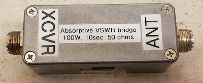
Figure 1:  The completed absorptive VSWR bridge.
Last year, I was "car camping" with a bunch of friends - all of which happened to be amateur radio operators.  Being in the middle of nowhere where mobile phone coverage was not even available, we couldn't resist putting together a "portable" 100 watt HF station.  While the usual antenna tuner+VSWR meter would work fine, I decided to build a different piece of equipment that would facilitate matching the antenna and protecting the radio - but more on this in a moment.

A bit about the Wheatstone bridge:

The Wheatsone bridge is one of the oldest-known types of electrical circuits, first having been originated around 1833 - but popularized about a decade later by Mr. Wheatstone itself.  Used for detecting electrical balance between the halves of the circuit, it is useful for indirectly measuring all three components represented by Ohm's law - resistance, current and voltage.

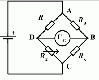
Figure 2:  Wheatstone bridge (Wikipedia)
It makes sense, then, that an adaptation of this circuit - its use popularized by Dan Tayloe (N7VE) - can be used for detecting when an antenna is matched to its load.  To be fair, this circuit has been used many decades for RF measurement in instrumentation - and variations of it are represented in telephony - but  some of its properties that are not directly related to its use for measurement that make it doubly useful - more on that shortly.

Figure 2 shows the classic implementation of a Wheatstone bridge.  In this circuit, balance of the two legs (R1/R2 and R3/Rx) results in zero voltage across the center, represented by "Vg" which can only occur when the ratio between R1 and R2 is the same as the ratio between R3 and Rx.  For operation, that actual values of these resistors is not particularly important as long as the ratios are preserved.

If you think of this is a pair of voltage dividers (R1/R2 and R3/Rx) its operation makes sense - particularly  if you consider the simplest case where all four values are equal.  In this case, the voltage between the negative lead (point "C") and point "D" and points "C" and "B" will be half that of the battery voltage - which means the voltage between points "D" and "B" will be zero since they must be at the same voltage.

Putting it in an RF circuit:

Useful at DC, there's no reason why it couldn't be used at AC - or RF - as well.  What, for example, would happen if we made R1, R2, and R3 the same value (let's say, 50 ohms), instead of using a battery, substituted a transmitter - and for the "unknown" value (Rx) connected our antenna?

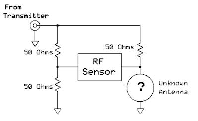
Figure 3:  The bridge, used in an antenna circuit.

This describes a typical RF bridge - known when placed between the transmitter and antenna as the "Tayloe" bridge, the simplified diagram of which being represented in Figure 3.

Clearly, if we used, as a stand-in for our antenna, a 50 ohm load, the RF Sensor will detect nothing at all as the bridge would be balanced, so it would make sense that a perfectly-matched 50 ohm antenna would be indistinguishable from a 50 ohm load.  If the "antenna" were open or shorted, voltage would appear across the RF sensor and be detected - so you would be correct in presuming that this circuit could be used to tell when the antenna itself is matched.  Further extending this idea, if your "Unknown antenna" were to include an antenna tuner, looking for the output of the RF sensor to go to zero would indicate that the antenna itself was properly matched.

At this point it's worth noting that this simple circuit cannot directly indicate the magnitude of mismatch (e.g. VSWR - but it can tell you when the antenna is matched:  It is possible to do this with additional circuitry (as is done with many antenna analyzers) but for this simplest case, all we really care about is finding when our antenna is matched.  (A somewhat similar circuit to that depicted in Figure 3 has been at the heart of many antenna analyzers for decades.)

Antenna match indication and radio protection:

An examination of the circuit of Figure 3 also reveals another interesting property of this circuit used in this manner:  The transmitter itself can never see an infinite VSWR.  For example, if the antenna is very low resistance, we will present about 33 ohms to the transmitter (e.g. the two 50 ohm resistors on the left side will be in parallel with the 50 ohm resistor on the right side) - which represents a VSWR of about 1.5:1.  If you were to forget to connect an antenna at all, we end up with only the two resistors on the left being in series (100 ohms) so our worst-case VSWR would, in theory, be 2:1.

In context, any modern, well-designed transmitter will be able to tolerate even a 2.5:1 VSWR (probably higher) so this means that no matter what happens on the "antenna" side, the rig will never see a really high VSWR.

If modern rigs are supposed to have built-in VSWR protection, why does this matter?

One of the first places that the implementation of the "Tayloe" bridge was popularized was in the QRP (low power) community where transmitters have traditionally been very simple and lightweight - but that also means that they may lack any sophisticated protection circuit.  Building a simple circuit like this into a small antenna tuner handily solves three problems:  Tuning the antenna, being able to tell when the antenna is matched, and protecting the transmitter from high VSWR during the tuning process.

Even in a more modern radio with SWR protection there is good reason to do this.  While one is supposed to turn down the transmitter's power when tuning an antenna, if you have an external, wide-range tuner and are quickly setting things up in the field, it would be easy to forget to do so.  The way that most modern transmitter's SWR protection circuits work is by detecting the reflected power, and when it exceeds a certain value, it reduced the output power - but this measurement is not instantaneous:  By the time you detect excess reflected power, the transmitter has already been exposed - if only for a fraction of a second - to a high VSWR, and it may be that that brief instant was enough to damage an output transistor.

In the "old" days of manual antenna tuners with variable capacitors and roller inductors, this may have not been as big a deal:  In this case, the VSWR seen by the transmitter might not be able to change too quickly (assuming that the inductor and capacitors didn't have intermittent connections) but consider a modern, automatic antenna tuner full of relays:  Each time the internal tuner configuration is changed to determine the match, these "hot-switched" relays will inevitably "glitch" the VSWR seen by the radio, and with modern tuners, this can occur many times a second - far faster than the internal VSWR protection can occur meaning that it can go from being low, with the transmitter at high power, to suddenly high VSWR before the power can be reduced, something that is potentially damaging to a radio's final amplifier.

While this may seem to be an unlikely situation, it's one that I have personally experienced in a moment of carelessness - and it put an abrupt end to the remote operation using that radio - but fortunately, another rig was at hand.

A high-power Tayloe bridge:

It can be argued that these days, the world is lousy with Tayloe bridges as they are seemingly found everywhere - particularly in the QRP world, but there are fewer of them that are intended to be used with a typical 100 watt mobile radio - but one such example may be seen below:

Figure 4:  As-built high-power Tayloe bridge with a more sensible bypass switch arrangement!  This diagram was updated to include a second LED to visually indicate extreme mismatches and provide another clue as to when one is approaching a match - see figure 7 at the bottom of the article.


Figure 4 shows a variation of the circuit in Figure 2, but it includes two other features:  An RF detector, in the form of an LED (with RF rectifier) and a "bypass" switch, so that it would not need to be manually removed from the coax cable connection from the radio.

In this case, the 50 ohm resistors are thick-film, 50 watt units (about $3 each) which means that between the three of them, they are capable of handling the full power of the radio for at least a brief period.  Suitable resistors may be found at the usual suppliers (Digi-Key, Mouser Electronics) and the devices that I used were Johanson P/N RHXH2Q050R0F4 (A link to the Mouser Electronics page is here) - but there is nothing special about these particular devices:  Any 50-100 watt, TO-220 package, 50 ohm thick-film resistor with a tolerance of 5% or better could have been used, provided that its tab is insulated from the internal resistor itself (most are). 

How it works:

Knowing the general theory behind the Wheatstone bridge, the main point of interest is the indicator, which is, in this case, an LED circuit placed across the middle of the bridge in lieu of the meter shown in  Figure 1.  Because RF is present across these two points - and because neither side of this indicator is ground-referenced, this circuit must "float" with respect to ground.

If we presume that there will be 25 volts across the circuit - which would be in the ballpark of 25 watts into a 2:1 VSWR - we see that the current through 2k could not exceed 25 mA - a reasonable current to light an LED.  To rectify it, a 1N4148 diode - which is both cheap and suitably fast to rectify RF (a garden-variety 1N4000 series diodes is not recommended) along with a capacitor across the LED.  An extra 2k LED is present to reduce the magnitude of the reverse voltage across the diode:  Probably not necessary, bit I used it, anyway.  QRP versions of this circuit often include a transformer to step up the low RF voltage to a level that is high enough to reliably drive the LED, but with 5-10 watts, minimum, this is simply not an issue.

Because the voltage across the bridge goes to zero when the source and load impedance are matched (or the switch is set to "bypass" mode) there is no need to switch the detector out of circuit but note that the LED and associated components are "hot" at RF when in "Measure" position which means that you should keep the leads for this circuit quite short and avoid the temptation to run long wires from one end of a large enclosure (like an antenna tuner) to the other as excess stray reactance can affect the operation of the circuit. 

Note:  See the end of this article for an updated/modified version with a second LED .

A more sensible bypass switch configuration:

While there are many examples of this sort of circuit - all of them with DPDT switches to bypass the circuit - every one that I saw wired the switch in such a way that if one were to be inadvertently transmitting while the switch was operated, there would be a brief instant when the transmitter was disconnected (presuming that the switch itself is a typical "break-before-make" - and almost all of them are!) that could expose the transmitter to a brief high VSWR transient.  In Figure 3, this switch is wired differently:

  • When in "Bypass" mode, the "top" 50 ohm resistor is shorted out and the "ground" side of the circuit is lifted.
  • When in "Measure" mode, the switch across the "top" 50 ohm resistor is un-bridged and the bottom side of the circuit is grounded.

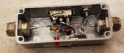
Figure 5:  Inside the bridge, before the 2nd LED was added
Wired this way, there is no possible configuration during the operation of the switch where the transmitter will be exposed to an extraordinarily high VSWR - except, of course, if the antenna itself is has an extreme mismatch - which would happen no matter what if you were to switch to "bypass" mode.

An as-built example:

I built my circuit into a small die-cast aluminum box as shown in Figure 5.  Inside the box, the 50 ohm resistors are bolted to the box itself using countersunk screws and heat-sink paste for thermal transfer.  To accommodate the small size of the box, single-hole UHF connectors were used and the circuit itself was point-to-point wired within the box.

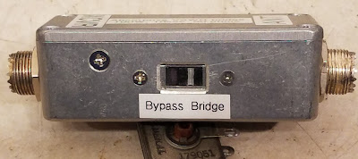
For the "bypass" switch (see Figure 6) I rescued a 120/240 volt DPDT switch from an old PC power supply, choosing it because it has a flat profile with a recessed handle with a slot:  By filing a bevel around the square hole (which, itself was produced using the "drill-then-file" method) one may use a fingernail to switch the position.  I chose the "flush handle" type of switch to reduce the probability of it accidentally being switched, but also to prevent the switch itself from being broken when it inevitably ends at the bottom of a box of other gear.
Figure 6:  The "switch" side of the bridge.

 
On the other side of the box (Figure 7) the LED is nearly flush-mounted, secured initially with cyanoacrylate (e.g. "Super") glue - but later bolstered with some epoxy on the inside of the box.
 
It's worth noting that even though the resistors are rated for 50 watts, it's unlikely that even this much power will be output by the radio will approach that in the worst-case condition - but even if it does, the circuit is perfectly capable of handling 100 watts for a few seconds.  The die-cast box itself, being quite small, has rather limited power dissipation on its own (10-15 watts continuous, at most) but it is perfectly capable of withstanding an "oops" or two if one forgets to turn down the power when tuning and dumps full power into it.  It will, of course, not withstand 100 watts for very long - but you'll probably smell it before anything is too-badly damaged!
 
Operation:

As on might posit from the description, the operation of this bridge is as follows:

  • Place this device between the radio and the external tuner.
  • Turn the power of the radio down to 10-15 watts and select FM mode.  You may also use AM as that should be limited to 20-25 watts of carrier when no audio is present.
  • Disable the radio's built-in tuner, if it has one.
  • If using a manual tuner, do an initial "rough" tuning to peak the receive noise, if possible.
  • Switch the unit to "Bridge" (e.g. "Measure") mode.
  • Key the transmitter.
  • If you are using an automatic tuner, start its auto-tune cycle.  There should be enough power coming through the bridge for it to operate (most will work reliably down to at about 5 watts - which means that you'll need the 10-15 watts from the radio for this.) 
  • If you are using a manual tuner, look at both its SWR meter (if it has one) and the LED brightness and adjust for minimum brightness/reflected power.  A perfect match will result in the LED being completely extinguished.
  • After tuning is complete, switch to "Bypass" mode and commence normal operation.
 * * *
 
Modification/enhancement
 
More recently (July, 2023) I made a slight modification to this bridge by adding a second LED driven by the opposite swing of the RF waveform so that it would not have any effect on the first - this LED designed to illuminate only under highly-mismatched conditions at higher power levels.
Figure 7:  The "enhanced" version with TWO LEDs.
 
As seen in the Figure 7 (above) the "original" LED is now designated as being yellow (the different color allowing easy differentiation) - but the second LED - which indicates a worse condition - is red and placed with a series 6.8 volt Zener diode (I used a 1N754A).  The idea here is that if the VSWR is REALLY bad and the power is high enough, BOTH LEDs will illuminate - but the "new" (red) LED will go out first as you get "close-ish" to the match.
 
Figure 8:  It has two LEDs now!

In testing with an open or short on the output and in "measure" mode the red LED illuminated only above about 15 watts, so this second LED isn't really too helpful for QRP unless the value of the 2k, 1 watt resistor is reduced.  Again, this isn't really to indicate the SWR, but having this second, less-sensitive LED helps with the situation when using a manual tuner in which the match is so bad that it's difficult to spot subtle variations in the brightness of +the more sensitive (yellow) LED - particularly at higher power levels.
 
 
This page stolen from ka7oei.blogspot.com

[End]

Tuesday, November 21, 2017

Matching the 2 and 6 meter cycloid dipoles to 50 ohms

The "Cycloid" dipole - a circularly-polarized antenna capable of (more or less) omnidirectional (toward the horizon) radiation was discussed in previous posts:
Figure 1:
The 6 and 2 meter Cycloid dipoles at the WA7X beacon.
The 2 meter cycloid dipole has been in service since 2001 and while the 6 meter
cycloid was (mostly) built at about the same time, it has been in service
only since 2015.
Click on the image for a larger version.
The 2 and 6 meter antennas were installed at the site of the WA7X beacon to impart a circular polarization on the transmitted signals, making them (generally) agnostic to the antenna used by the listener - which is to say that it wouldn't matter whether the receive antenna was vertically or horizontally polarized.  The use of circular polarization also reduces the problem where the ionospheric reflection may rotate the signal to the "other" plane and cause fading at the receive location owing to cross-polarization.

While this antenna is described as being "omnidirectional", that is not true in the proper sense of the word.  Its circularity and most of its radiated power is directed toward-ish the horizon (at some elevation angle) in all directions while relatively little energy is radiated at a high angle upwards or downwards - and what is being radiated in those directions not likely to be very circular.  As with any antenna, the proximity of the coaxial cable, metallic support and feedline will, no doubt, skew the pattern in some way - and this antenna is no exception - but this is unavoidable.

While the dimensions of the "antenna" part of the Cycloid dipole are spelled out in the linked article(s) above, details related to matching of these antennas to 50 ohms is not - with only the suggestion that a "1/2 wave matching network" be used.  While this matching network is very simple, it may be unfamiliar to some, so what follows is a paraphrased response to an email on this very question.

Matching the cycloid dipole to 50 ohms:

While I carefully noted the dimensions of the dipole when I designed them, we never precisely measured the various dimensions of the matching networks of the 2 and 6 meter Cycloid Dipoles as the need for precise replication would render them as mere "starting points" and they are simply stub-tuned 1/2 wave sections - only the dimensions of the actually "antenna" portion are on the web page.

In retrospect, a full 1/2 wave section was probably an overkill as a 1/4 wave may have sufficed - but that "extra" bit of open-wire balanced transmission line (e.g. the portion of the pipe between the coax tap and the "cycloid" part of the antenna) worked out well to provide physical support, rigidity, and counterbalance, would not cause any significant loss, and it all but guaranteed that we would be able to find a good match. in almost any conceivable situation.

The details of the matching network and its tuning are thus:
  • We used about 1/2 wave length of copper tubing protruding from the "back" of the antenna, used also to support the main antenna body.  As can be seen from the pictures, it was folded upon itself, zig-zagging to reduce its overall size.  This extra weight can help to counter-balance the antenna itself.
  • There is a 1/2 wavelength coaxial balun to go from 50 ohms unbalanced to 200 ohms balanced using small 50 ohm coaxial cable.  This type of balun well-described in literature and one of several online calculators may be found here:  http://n-lemma.com/calcs/dipole/balun.htm .  For the 2 meter antenna we actually used some small, 50 ohm hardline (the RG-58-sized equivalent of "UT-141" PTFE coax) that was obtained on the surplus market, but RG-8x or even RG-58 would have been fine.
  • When the antenna was tuned, it was mounted on a nonmetallic support (a fiberglass ladder) placing it several feet/meters above the ground and an MFJ analyzer was connected to the far end of the coax (10-15 feet away) to minimize the effect of having a person too close to the antenna and affecting tuning.  For initial tuning, it should be mounted to the same type of mast as that which will be used for permanent mounting.  For the antennas at the WA7X beacon, plastic pipe has proven to be durable with the 6 meter antenna being mounted using black ABS sewer pipe.  In the case of the 2 meter antenna, it was mounted using some PVC piping that seems to be holding up despite being out in the weather for well over a decade.
  • We prepared two nonmetallic sticks - 5-6 feet long (1x1, wood dowels, bamboo, small plastic pipe, etc.) and one of these had a piece of heavy wire to use as a shorting stub and the other had the balanced (200 ohm) side of the coaxial balun, also connected to 2 wires. The wires/balun were simply taped to the end of the stick to allow contact to be made.
  • Make sure that the copper pipe from which the matching section is made is clean and free of oxide using steel wool or sanding with fine-grit paper to allow a reliable connection while sliding the connections back and forth - both for finding a match and for ease of soldering.
  • At the position farthest from the "antenna" portion, the sliding shorting bar was placed while sliding connection to the balun was placed near it, on the "antenna" side of the shorting bar.
  • With the sticks, the two pieces (coax attachment and short) were slid around to achieve 50 ohm match.  While the two sliding portions are held in place, another person marks their position with a permanent marking pen on the antenna when a match is found.  It is easier to move the connection on the balun back and forth while watching the VSWR while slowly moving the shorting bar back and forth, looking carefully for a match.  Typically, the two connections will be fairly close to each other as seen in Figure 2, below.
  • Once a preliminary match is found, the sliding shorting bar is replaced with a piece of heavy, solid wire (#10-#14 AWG) that is wrapped around the pipes at the marked position. The other sliding bar (on the balun) is then re-checked for a good match, the shorting bar's position tweaked as necessary.
  • Once the position of the shorting bar has been established, the wire on the balun section is wrapped around the pipe at the location of the best match, allowing the wooden stick to be removed.  The positions of the two connections are then tweaked by sliding the wires back and forth for best match.
  • The two connections are soldered in place, and the match re-checked.  If it is OK, the connections are sealed and the match re-checked and adjusted as necessary.
  • In both Figure 1 and Figure 2 one can see small pieces of acetal (e.g. Delrin tm) plastic on the matching network - this material being chosen for its low RF loss characteristics and its durability to UV exposure.  Note that PTFE (a.k.a. Teflon tm) would have also worked well.  Some of the pieces (those at the far left edge of the matching section) are used for mechanical support, but the others are used for fine tuning:  The position of these pieces of dielectric slightly alter the tuning.  After the antenna was fully assembled, these were moved back and forth for the best match and secured in place with blobs of RTV (e.g. Silicone tm) sealant on both sides.  (RTV does not stick to this plastic, but the blobs keep it from moving about.)
As can be seen in Figure 2 on both the 2 and 6 meter antennas, the attachment point of the balun is fairly close to the shorting bar.  The proximity of the coaxial cable balun to the match may affect tuning a bit, so it must be fixed into place before the final tuning is done.

Figure 2:
Annotated image showing the locations of the shorting bars, coax baluns, balun connections and the rain shields on
the 6 and 2 meter cycloid dipoles.  The matching network on the 6 meter antenna is longer than
necessary to allow its far end - which is electrically neutral - to be clamped to the mounting pipe and attached to
a ground wire for static discharge/lightning protection.  The connecting cables were secured with good-quality
electrical tape and black "zip" ties, which were also covered with electrical tape to protect them from UV.
Click on the image for a larger version
Note that for each antenna a "snow/rain shield" was placed over the top of the matching section to minimize the effects of moisture, but the addition of this shield did change the tuning, as did the addition of RTV sealant on some of the connections, so final tuning must be done with such hardware and sealant in place.

The entire procedure is a lot easier if there are 2 or 3 people participating as it is pretty tricky for a single to hold two wires on sticks in place and mark them. If there is only one person available, the shorting bar wire would be wrapped around the (clean!) pipes at a position correlating to about 0.4 wavelength on the pipe and the balun portion slid back and forth to see a "dip" in the VSWR, iteratively adjusting the shorting bar back and forth experimentally while sliding the connection from the balun to get the best match.

As I noted, it is possible that a 1/4 wave section would have been fine, but we just used the 1/2 section as there would be no doubt that it could be matched - and we wanted to minimize the hassle related soldering/unsoldering things as much as possible.  Importantly, this type of match - using the large pipes and "open wire" line - is very low loss compared to many other matching networks (e.g. those using small wound coils and discrete capacitors) and it contributes to the mechanical strength of the antenna itself.

[End]

This page stolen from ka7oei.blogspot.com