Why ask the question?
 |
| Figure 1: Some of the scenery along the Green River - one of the "wider" areas, closer to the confluence, where coverage was a bit less of a challenge. Click on the image for a larger version. |
Unless you have been in this part of the U.S., it is difficult to appreciate how large and remote it is: The area covered is larger than some U.S. states and several European countries, all with a total population of less than, say, 100,000 people. What's more, even on "flat" ground - if you can find it - cellular telephone coverage is spotty at best and if you are within some of the narrow, deep gorges of the Colorado or Green rivers it is all but hopeless: Even satellite telephones have been proven to be of limited use in some of these areas due to the restricted view of the sky!
So why did we care?
If there are several hundred people and dozens of boats on this hazardous river course over a period of several days, camping and boating in the wilderness, there is very likely "something" that will happen that will require that help be summoned. Whether this is a mechanical breakdown, running out of gas, or some sort of health emergency the need is the same: Help may be required.
To this end there were a number of "rescue boats": Several patrolling the main group of boaters, one parked at the confluence to make sure that no-one managed take a wrong turn and go down "Cataract Canyon" (read about that set of rapids here - link) and a "sweep" boat at the end that makes sure that no-one is left behind. Since the 1960's it was amateur radio that had been used as the basis for communications.
 | |
| Figure 2: One of the many types of HF antennas that have been used over the years on the Friendship Cruise. This is a high-Q magnetic loop antenna, tuned for 75 meters. A 2 meter collinear (5/8 wave over 1/2 wave) may be seen in the background. Click on the image for a larger version. |
Back in the heyday of the Friendship Cruise - in the late 60's and into the mid-late 70's - there were hundreds of boats on the river which meant plenty of breakdowns, people running out of gas, problems due to the imbibing of alcohol, and other "mishaps" - and the rescue boats coordinated exclusively via 75 meter HF. To be sure, not all rescue boats were radio-equipped, but enough to "spread the word" if something were to happen.
This mode of communications worked well over the 100 mile or so range required since during the daytime, this band offers good, local coverage and the "straight up, straight down" nature (now called "NVIS" - link) of the daylight propagation was good for getting in and out of the narrow (1/4 mile, 400 meter deep) river gorges. Other frequencies such as those around 10 meters and even VHF had been tried, but they barely got around the next bend in the river - let alone out of the canyon to... where?
Flash forward to the mid 1990's. By this time HF rigs were much smaller than the tube-type rigs that had been used in the 60's and early 70's, but it was desired that VHF be used as it was easier to equip boats with that sort of gear - perhaps not all of the rescue boats, but at least some of them on which licensed hams would be carried. Some of them carried VHF rigs and communicated successfully with temporary stations set up in strategic, high locations near-ish the river. The problem was that there was no single location that offered good communications for both rivers over any reasonable distance.
By 1997 we decided to try something new. A site on public land had been found that covered much of the course on the Colorado river and due to the "lay of the land" the geography was in favor of being able to get signals in and out of it over most of that portion of the course. At around the same time, almost by accident, it had been discovered that a site called Panorama Point, administered by Canyonlands National Park, offered the possibility of covering at least some of the Green River: In a case of serendipity I had been on a rescue boat the year before and a group of hams camping there just happened to stumble across our limited VHF activity and were kind enough to do occasional propagation checks as I moved along the course on the 'Green: The results seemed promising.
Armed with that information a weekend was carved out for a Jeep trip to inspect Panorama Point and it was visited after a drive on a very rugged, high-clearance four-wheel drive road. After arrival we did some exploring and a site was found for a separate receive station that was distant from the transmitter - and we even talked to another ham on 2-meter simplex in a location farther away than we expected it to cover. Encouraged, we bounced again over the rugged roads and returned to the ranger station and reserved the site. The head ranger for the district had no problem with what we wanted to do - as long as we didn't deface anything, did not bother any of the wild animals, and "packed out" what we packed in - so a special use permit was issued for the event.
Returning home, I knew that I had some work to do!
Design goals for the portable repeater:
At this point you may be asking yourself, "Self, what in the hell does this have to do with repeaters or sensitivity?" Don't worry - I'm getting to that!
In analyzing the geography and taking advantage of an early topography-based propagation analysis program I determined that while the Panorama Point site had a high vantage point and was probably the very best site that existed to potentially cover the Green River, it likely did not have good radio coverage of the river itself over most of that same area - just the tops of the gorges through which the boats would travel.
This meant several things:
- It would be necessary to radiate as much RF power as practical, blasting the landscape with RF in the hopes that at least some of it would find its way to the river at the bottom via refraction and/or reflection.
- I would have to do everything that I could to extract the weakest-possible signal from the receive system to grasp the users' signals that bounced their way out of the very deep river gorges.
- It had to be portable. This site was at the end of a rugged, high-clearance four-wheel drive road at an elevation of approximately 6200 feet (1890 meters) above sea level with absolutely no amenities. Since everything for the repeater and our very existence had to be crammed into as few vehicles as possible (usually 2) we needed to keep the bulk to a minimum!
 |
| Figure 3: One of the GaAsFET preamplifiers, in place on a Yagi receive antenna. These amplifiers are based on a WA5VJB design and use the (now obsolete) MGF1302 GaAsFET transistor. It is estimated that they have a noise figure in the range 0.8dB or lower. Click on the image for a larger version. |
That which limits - Thermal noise!
I constructed two mast-mounted GaAsFET preamplifiers (18-20 dB gain, somewhere between 0.5 and 0.8 dB noise figure) and a two-receiver voting controller, but I did so planning to "hedge my bets" as much as possible. Already having a pair of 5 element Yagis and two identical VHF receivers, the plan was to marry everything together to construct a voting repeater. The link back to the 2 meter transmitter site was via a low-power UHF transmitter (a slightly-modified HT - see Figure 6) and in addition to linking our receive site to our own transmitter, this transmitter's signal was also received at the "other" site covering the Colorado River, thus tying the two repeaters together.
Having constructed these receive systems I decided to check the sensitivity and found that the 12 dB SINAD sensitivity, with the GaAsFET preamplifier inline, was approximately 0.085 microvolts as verified on several different pieces of test equipment!
This brought to mind the question: "How sensitive could an Earth-based repeater using standard +/- 5 kHz deviation FM possibly be, in theory?"
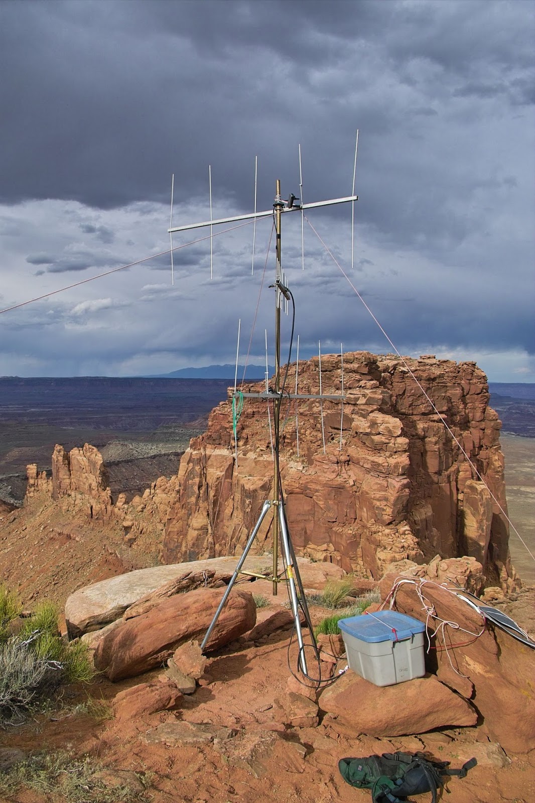 |
| Figure 4: The receive site for the repeater, entirely solar- powered. While not obvious from this picture, this site was on a narrow outcropping of rock and surrounded on three sides by 1200- foot (365 meter) cliffs! Because there was also rock and distance between it and the transmitter site, there was excellent TX/RX isolation, eliminating the need for lossy cavities/filters in front of the preamplifiers. In the box, safe from weather, were the radios, voting/power controller and 30-ish amp-hours of batteries. Click on the image for a larger image. |
For any receive system with specified attributes (e.g. detection bandwidth and modulation method) there is one fundamental, limiting factor that imposes an absolute limit on how sensitive it can be: Thermal Noise. This thermal noise comes from two places:
- The equipment itself, and
- The environment in which the receive system is used.
For an example, consider a piece of metal. At room temperature, it does not "glow" visibly, but if you were to heat it, it would begin to glow - very dull red at first, but as it got hotter, it would become closer to being "white hot." As it cools again, its glow disappears once more to our vision. Just because it may have cooled off to room temperature, don't think that it isn't still "glowing" - because it is! As it turns out, any object that is above absolute zero does glow - not only at infrared wavelengths as you may have seen in footage of police finding criminals in the dark using "heat sensitive" cameras, but also at plain radio wavelengths where it manifests itself as noise.
Keeping in mind that all "warm" surfaces "glow" at radio wavelengths, one can complete the analogy by likening a radio signal to a light source on a glowing surface: If the surrounding surface is "glowing" more brightly than the radio signal, that radio signal is simply lost!
The magnitude of this noise with respect to the receive system can be calculated using this equation:
N = k * T * B
Where:
When numbers are crunched, assuming a 300K (about 80 degrees F, 27C) temperature and a 15 kHz receiver bandwidth, we can calculate that in a 50 ohm system, as is used on a typical receiver, this is equivalent to a noise voltage of approximately 0.056 microvolts when using an isotropic antenna completely immersed in a 300K environment.
- N = noise power in watts
- T = temperature in Kelvin
- B = bandwidth in Hz
- k = Boltzmann's constant - which is approximately 1.38x10⁻²³ (expressed in Joules per kelvin, or J/K)
(Yes, that also means that there is an equivalent signal noise voltage of 0.056 uV - assuming the same detection bandwidth - coming out of a 50 ohm dummy load that is at a temperature of 300K: It is through the use of the intrinsic noise of dummy loads that EMEers - those that engage in Earth-Moon-Earth communications - can quickly check the relative performance of their receiver/preamplifier system by comparing the noise level of the "hot" dummy load with that of the "cold" sky.)
The above example assumes that we are receiving a signal using an isotropic antenna, surrounded on all sides by matter that is at 300K. While this isn't exactly the case in a "real world" scenario, it is a reasonable approximation of actual operation of a receive system in which the signals are emanating from the surface of the Earth.
The numbers calculated above illustrate that our receive system is, in fact, limited by more than the fact that the signal is just getting weak: The signal is, in fact, being lost in thermal noise being radiated by the earth itself, hence the nature of the title of this article!
But it gets worse!
If you have loss in front of your receive system, this is the equivalent of a noise source. For example, a 3dB loss in front of a theoretically-perfect preamplifier (e.g. 0 dB noise figure, lots and lots of gain) due to coaxial cable, a bandpass cavity, connectors or anything else will still cause the system consisting of that 3dB loss and our "perfect" preamplifier to have an apparent 3dB noise figure: Once you lose signal due to attenuation and it goes into the resulting thermal noise, it is gone forever and no amount of gain or any type of amplification after this loss can or will bring it back!
This is exactly why the preamplifier is located at the antenna as depicted in Figure 3: The only losses ahead of the preamp are those of the matching networks of the antenna and preamp and the kludge of connectors required to mate the antenna to it. The losses in the coaxial cable after the preamp and the noise figure of the receiver itself still matter, but are comparatively small contributors to the overall receive system noise figure once gain is introduced into the system.
How much sensitivity do we really need?
| 12 dB SINAD Sensitivity |
Approx. Noise Figure (dB) |
12 dB SINAD Sensitivity |
Approx. Noise Figure (dB) |
|
| 0.1 μV | 3.4 | 0.3 μV | 10.7 | |
| 0.125 μV | 4.6 | 0.4 μV | 13.1 | |
| 0.15 μV | 5.7 | 0.5 μV | 14.9 | |
| 0.2 μV | 7.6 | 0.75 μV | 18.4 | |
| 0.25 μV | 9.2 | 1.0 μV | 20.8 |
With my receivers having a "barefoot" (no preamplifier) sensitivity of 0.15 microvolts for 12 dB SINAD (approximately 5.7 dB Noise Figure based on Figure 5) I calculated that the worst-case sensitivity, taking into account expected cabling and connector losses and assuming a 0.8 dB noise figure for the preamps, that the overall system noise temperature was likely close to 95k, or about 1.23 dB. Clearly this was "quieter" than the 300k noise from the Earth itself! By changing the design of the preamplifiers I could have increased their gain and reduced the system noise figure even more, but doing this might have risked front-end overload of the receivers by also increasing the level of the (strong!) nearby transmit signal, effectively reducing system performance.
Without cryogenic cooling of the entire planet (which would be really bad for most of us!) much better system sensitivity than this was impossible to obtain with the aforementioned receive system
I now knew that my receiver sensitivity was a reasonable match for the sort of "minimum usable" signals that one might experience in an "Earth-bound" receive system: If I'd made my receive system completely noise-free I would have gained only a dB or so at most since I was already very close to the absolute limit imposed by the noise environment of the Earth - and this did not take into account the antenna system itself.
Exceeding the limits of thermal noise:
The use of directional antennas
The next obvious step in improving the receive system performance still more was through the use of directional, gain antennas. Because the hub of activity on the rivers was toward the north we had the luxury of being able to use such antennas since there was no need for omnidirectional coverage. By limiting the the "field of view" of the receive system with these directional antennas (5 element Yagis) and with the apparent signal gain provided, the absolute signal levels (which included the inevitable thermal noise of the Earth) were increased at the input terminals of the preamp, additionally overcoming deficiencies that might be present in the receive system, not to mention helping reject the strong transmit signal 600 kHz away from the receive signal off the backs and sides of the beam as well as rejecting other signals (from where?) that might encroach from other directions.
With this configuration, pretty much all of the signal from the distant transmitter - plus Earth thermal noise - that was being intercepted by the Yagi was being presented to the receiver and there was really nothing more that could be done in practical terms to enhance it further.
Receiver diversity
Even with the preamplifiers and gain antennas, I still wanted to go another step further in improving the apparent sensitivity of the receiver system and this was done by using multiple antennas and receivers in a VOTING arrangement.
 |
| Figure 6: The two matched receivers - modified RCA VHF TacTecs, the UHF link transmitter - a slightly modified Yaesu FT-470 - and the PIC-based voting controller/solar charge controller. These TacTecs have quite good strong-signal handling due to the use of a moderate amount of properly-distributed RF gain and a passive diode-ring mixer - somewhat unusual to find in radios these days! These TacTecs were modified to bring out discriminator audio and the squelch "noise voltage" to interface with the voting controller: While the absolute squelch level was fixed in the voting controller, the radio's squelch knobs still adjusted the "noise voltage" gain and thus allowed, indirectly, the squelch of each receiver to be adjusted. The squelch threshold was adjusted for an approximately 3 dB SINAD quieting audio signal: While noisy, this is still quite copiable to the trained ear if the transmitter's modulation is adjusted properly! Click on the image for a larger version. |
Because each receiver had its own antenna and preamplifier, and since the two antennas were physically separated from each other in the vertical plane and pointed in slightly different directions, it was more likely that at least one of these receiver/antenna combinations would intercept at least a fragment of the weak, refracted/reflected signal emanating from the distant canyon bottom.
The amount of "gain" that this sort of arrangement provides is difficult to quantify as it varies wildly with circumstance, but with these indirect, "bouncy" and multipath-laden signals emanating from the bottoms of distant gorges it is certainly positive!
Comparing to a "normal" repeater's receive system:
Let us consider the typical overall sensitivity of a typical amateur repeater. Assuming that there is NO site noise at all (quite unusual for a busy, shared communications or broadcast site!) and an intrinsic receiver sensitivity of 0.15 microvolts - a reasonable (or even optimistic) number for modern gear - and let us add up the various losses that might be found in a typical repeater system:
- Feedline losses: 2 dB
- Duplexer/cavity losses: 2 dB
- Miscellaneous losses: 1 dB
Would a digital modulation scheme have helped?
With a number of digital modes available for use on VHF such as "D-Star", "DMR" and "System Fusion" it would be reasonable to ask if using a digital mode instead of an analog signal would have improved overall system performance. The quick answer is NO. It can be demonstrated that when one approaches a "quieting" of around 12dB SINAD - a slightly noisy but perfectly copiable analog signal - all popular digital modes (those mentioned above) start to fall apart - and using a "voting" receiver system (if one is available!) becomes rather complicated. If one has a "trained ear" it is even possible to copy an analog signal when its SINAD has degraded to just 3-6 dB - a signal far too weak to even get any digital data through at all - provided that the person at the "other end" is speaking clearly and fully modulating the transmitter. (For a demonstration of weak-signal FM versus weak-signal D-Star, go here - link.) What would work significantly better than FM in terms of weak-signal performance by a significant margin (perhaps 10-fold!) and resistance to multipath distortion is good, old-fashioned SSB owing to its narrower bandwidth and more efficient means of conveying voice on the carrier. In theory it should be possible to construct an "SSB Repeater" compatible with the modern, all-mode and readily-available transceivers, but since this would add apparent complexity on the part of each user, this was not seriously considered! |
You may know that with a "typical" repeater consisting of a single antenna and duplexer that it not uncommon to experience a bit of "desense". This is where some of the energy of the transmitter causes a decrease in sensitivity of the receiver, making the situation even worse!
Consider that both the receiver and transmitter systems for this portable repeater system used Yagi antennas that offered approximately 10dBi gain on both receive and transmit. When one takes into account the difficult nature of running full duplex on a Yagi with the possibility many "nonlinear" junctions causing a minute amount of energy to be produced and cause some desense - plus the fact that this had to be a "portable" repeater - one can chose to see why we chose to avoid the bulk, expense, loss, and awkwardness of any cavities at all and used a repeater with a geographically separated transmitter and receiver.
All of this leads to an interesting question: Would an "ordinary" repeater, with its typical single transmit/receive antenna multiplexed with cavities and commensurate losses, plopped down at this location have provided useful coverage in this particular instance?
Based on the observed signal levels: No, I don't think so!
The repeater in actual use:
This repeater system was used, with minor modifications, from 1997 through 2011, the most recent Friendship Cruise, and the software for the homebrew, PIC-based voting controller was modified to include charge control of the solar panels, implement power-saving features for the receivers and to report some telemetry with the IDs. On the transmitter side a 300 watt amplifier was typically used with a 5 element Yagi to blast well over 2kW EiRP in the direction of the boats - all without "desensing" the repeater's receivers in the slightest even though the receive site was generally within the pattern of the transmit antenna!
 |
| Figure 7: The transmit site. The transmit antenna, a Yagi (a 7 element, in this particular case) , was located atop a 25 foot (7.6 meter) mast located only a few 10's of feet away from 1200 foot (360 meter) cliffs on two sides. It was fed with approximately 300 watts of 2 meter transmit power, directed toward the location of the activity on the river yielding well over 2kW EIRP. Power was provided by a bank of 100 amp-hour lead-acid batteries that were recharged twice a day at 50-80 amps with a generator. In the foreground may be seen the UHF link antenna for receiving the signal from our own receive site and the link from the "other" repeater covering the Colorado River as well as a "backup" 2 meter Yagi used during set-up and in case the main repeater system were to go off line for some reason. The transmitter itself was a Kenwood TM-733A operating in "half-crossband" mode. Because the ID was provided by the controller at the receive site - and the main transmitter was relaying this UHF link - everything was legal! Click on the image for a larger version. |
It is fair to say that the repeater worked phenomenally well! In the few days that it was online for the event each year that it was used it was not uncommon for someone to stumble upon it while scanning, sometimes from a very long distance, well outside the intended coverage area. Even though it was intended to cover mainly the Green River's course it turned out that there were very few places on either the Green or Colorado Rivers that the repeater did not cover - or at least where a "hot spot" could not be found.
Because we were "stuck" out in the middle of nowhere at this site, many hours drive from "civilization" for 4-5 days, we had plenty of time to observe how the repeater system worked.
As you can imagine, in the first couple of years that the voting system was used its behavior was carefully observed to see if it was really helping dig out signals and at times, the local speakers on the two receivers comprising the voting system were turned up while a distant station was transmitting. It was often the case that one could hear the transmitting station fade out of one receiver - but not the other - as the signal bounced its way out of the deep river gorges and off the rocky rims above, this on two antennas that were about a wavelength apart and pointed in slightly different directions, proving the worth of the voting receivers while offering an eerie "stereo" type effect.
Not surprisingly, standing at the receive site and switching to the repeater's "reverse" (the input frequency) in such situations while listening on a handie-talkie using a large whip typically yielded either a barely detectable signal or nothing at all while the repeater happily relayed signals that were often full quieting!
One of the interesting aspects of this system was the difference in the "sound" of weak FM signals on this system. On a typical FM repeater system a weak signal develops "popcorn" noise as the signal gets weak - a rather strong, staccato series of random noise pulses that appear on the audio as signals get weak. While these receivers exhibited this same behavior when connected directly to an antenna, when configured as they were with this system using the GaAsFET, mast-mounted preamplifiers and "Earth noise" dominating this noise and "popcorn" was almost entirely absent with weak signals seeming to disappear into a sea of steady, even "hiss" instead, not too unlike what one hears on VHF/UHF SSB signals.
In the case of Earth-to-Space communications, great care is taken in the
design of the antenna system to prevent it from "seeing" the "Earth
noise" as much as possible. If this is done it is possible to construct
a receive system that will hear spacebourne signals that are much
weaker than those that could possibly be detected from Earth-based
sources. In fact, with such systems it is not uncommon to be able to
see a significant increase in "no signal" readings when the antennas are
lowered to zero elevation and pick up "Earth noise" as compared to when
they are pointed into space - unless they are pointed at the (noisy!)
sun - but that's another topic altogether!
|
* * *
Alas, the Friendship Cruise has not been held for several years now as the combination of unprecedentedly low water flow rates in one or both of the rivers and the apparent waning interest has taken its toll. For those that were involved in the amateur radio portion it was a fascinating exercise in several of the most important aspects of the hobby:
- Being able to communicate for the public good for the safety and well-being of all of those involved.
- To give those involved practical, real-world experience in operating out in the field under "less than ideal" conditions where there is absolutely no backup via the commercial or public infrastructure.
- To try out new ideas and techniques to make communication work in a very challenging geography!
[End]
This page stolen from "ka7oei.blogspot.com".
Very readable, well done.
ReplyDelete73, Bob KIØG
Thanks!
Delete73,
KA7OEI
All these technical challenges added to this captivating story makes you article pure gold for a ham. 73 from PY2JF
ReplyDeleteThank you for reading!
Delete