Monday, March 31, 2014

Examining the Glencom VC510 UHF to L-Band Upconverter

This is a curious little device - of which several have fallen into my hands.

Often available on EvilBay for fairly cheap, these are in some nice, die-cast Hammond (tm) aluminum boxes approximately 7.25"L x 4.5625"W x 2.125"H (185mm x 118mm x 54mm) in size with two good-quality "N" type connectors connected with short lengths of UT-141 PTFE cable and an board-mounted "F" connector.

The question that seems to be asked by others who run across these devices on the GoogleWeb is "What are these for?"

Well, I can answer that.
Figure 1:
The case of the VC510 "Upconverter"
Click on the image for a larger version.

From the early 90's and into the mid 2000's Hughes Network Systems had a VSAT (Very Small Aperture Terminal Satellite) product referred to as "ISBN" - and an early version of this was called the "Type 2" with much of the hardware being made by NEC in Japan.  Connecting the rooftop satellite transceiver - typically operating in the U.S. market on the Ku band - to the indoor data interface unit was a single coaxial cable that carried not only the power, but all of the myriad control signals used for transmitting - but also the entire 500 MHz of the satellite passband.

Now, you would think that, like everything else satellite that the receive signal would occupy the "L-Band" range of 950-1450 MHz, being down-converted from 11700-12200 - but you would be wrong.  For various and sundry technical reasons, the receive signals were conveyed on the cable from 1000 to 500 MHz - "upside-down" owing to a "high-side" local oscillator within the rooftop unit itself, making it incompatible with L-band gear.

Except that NEC/Hughes had thought of that:  They'd handily included a simple converter within the unit that, using a 1950 MHz oscillator, converted that "upside-down" signal to the proper 950-1450 MHz L-band signal again.

Except that it didn't really work all that well.

Figure 2:
The circuit board of the VC510.  There is also a version that has a
surface-mount 74LS parts instead of the DIP parts shown that is
(pretty much) electrically identical in all other ways.
Click on the image for a larger version.
You see, at about this time, digital signals - data, voice and video - were starting to appear on the satellite bands and this built in L-band converter - while adequate for wideband analog video signals was too unstable and inaccurate for digital signals so the device pictured above was devised to fit the bill, doing what the built-in converter should have done correctly in the first place!

Dissecting the VC510:

Essentially, the VC510 does the same thing as the converter in the original NEC unit should have done:  Mix the 1000-500 MHz signals with a 1950 MHz local oscillator to yield a stable, clean 950-1450 MHz L-band signal - but how did they do it?

To answer this question, I decided "reverse-engineer" the board and came up with the diagram, below.

Figure 3:
A reconstructed circuit diagram of the VC510.
The component designations are arbitrary and are not marked on the board anywhere but with a a circuit this straightforward, it should be pretty easy to work out what's what!
Click on the image for a larger version.
How it works - The frequency converter portion:

The signal from the rooftop unit is coupled via the "line sampler" - a stripline directional coupler etched onto the circuit board that also extracts a bit of the DC power from the coaxial cable as well:  This directional coupler has a negligible effect on the signals passing through it.

From this directional coupler is an elliptical-type low-pass filter that removes signals above approximately 1000 MHz (there may have been a signal at around 1350 MHz - I don't know this for certain) and is amplified by U1 by about 12dB which is then applied to U2, an RMS-11X doubly-balanced mixer which causes a loss of approximately 7 dB.  Mixed with the 1950 MHz signal from the local oscillator the output is passed through an attenuator and then another low-pass filter with a cut-off frequency of approximately 1800-2000 MHz and then amplified by U3 by for another 12dB gain which is the L-Band output.

The local oscillator:

Q1, an AT-41511 transistor along with varactor diode D1 forms a VCO, the output of which is coupled via an attenuator pad to U4, a MMIC that amplifies the signal by 10 dB - some of which is siphoned off and applied to U6, an MB506 divide-by-256 prescaler that takes the 1950 MHz signal down to 7.6171875 MHz (when the PLL is locked) - while the remainder goes to U5 to be amplified again and applied to U2, the RMS-11X mixer.

The main reference oscillator is based around a 7.6171875 MHz (approximately!) crystal, using a 74LS00 NAND gate and fed to a pair of 74LS74 D-type flip-flops wired as a "charge-pump":  If the frequency is too high, a bit of charge is subtracted from C28 and added to C29 and vice-versa if the frequency is too low. U9, a TL071 op amp which is used as a loop filter/integrator and does the phase/frequency control, locking the VCO to the frequency reference provided by the crystal.

In all, there's nothing about the above circuitry that is particularly fancy or requires exotic components - just the application of fairly inexpensive, standard components using designs that had been around since the late 60's or early 70's - except, perhaps, for U6, the prescaler.

Notes:
  • U1 and U2 are very similar to the MSA-2086 (but a different package) and good from DC to at least 2.5 GHz and typically have 10-12 dB gain over this range and a 6-7 dB noise figure with a 1dB compression power output of around +4dBm  The typical bias current is 25 mA with 5.0 volts at the output terminal.   This device is generally equivalent to the Mini-Circuits MAR-2.
  • The MSA-1105 used for U4 and U5 is good from below 50 MHz to 1300 MHz at the -3dB points with a typical gain of 10-12 dB and usable to over 2 GHz with a gain reduction to around 6dB.  Up to 1.3 GHz the 1dB compression power output is typically +18dBm dropping to around +15 dBm at 2 GHz with the noise figure below 1 GHz typically being below 4 dB and rising to around 5.5 dB at 2 GHz.  The typical bias current is 60 mA with 5.5 volts at the output terminal.  This device is generally equivalent to the Mini-Circuits MAV-11.

Testing on the workbench:

Surprisingly, the unit produced a fairly good CW "note" - almost suitable for CW/SSB operation - something that could have probably been cleaned up had a better crystal reference oscillator used.  With no modification at all, the VCO's lock range turned out to be approximately 1600-2150 MHz by varying the frequency fed to the crystal oscillator from 6.25-8.398 MHz - but it could probably extended by modification of the cutting/bridging some traces in the VCO section.

As it is, the "gate-type" crystal oscillator based on the '7400 is not accurate/thermally stable enough for SSB/CW operation - or even narrowband FM operation - so if this sort of operation is anticipated, a different, more thermally-stable oscillator is likely required!

So, what's it good for?

It's hard to say, but some of the ATV folks seem to have found use of these devices as 23cm and/or 13cm ATV converters and in theory it could be used to convert 2 gig WiFi to other frequency ranges or even be the front end of a simple spectrum analyzer for the low GHz range.

Because the RMS-11X mixer is rated for as low as 5 MHz on all ports, up to 1000 MHz on the IF port (to which the F-connector sends the signal) and to 1900 MHz on the LO and RF ports, it should be perfectly usable to at least 2500 MHz - perhaps higher, especially if preceded with a low-noise amplifier.


A few comments about modification:

- L1/L2/L3 are circuit board inductor traces that can be sliced.  If the accompanying capacitors are removed, the low-pass response of this filter is eliminated and useful response is extended well past 2 GHz.

- L4 is a circuit board inductor and its low-pass response is also eliminated if its accompanying capacitors are removed.

- If the L1-L4 filtering is removed, additional (narrowband) filtering for the frequencies of interest should be added to the input and output to prevent/minimize spurious responses.

- As noted on the schematic, there are also some traces that could be sliced/jumpered in the VCO section.  It is likely that modification of these could change the VCO tuning range from that noted above.

Please note that the rating of the prescaler, MMIC amplifiers and the mixer would limit the upper end of the useful range of the VCO to something in the 2.2-2.4 GHz range at most, but it should be possible - in theory - to take the VCO down to well below 1 GHz with the addition of a physically larger inductor.  If this is done, one might want to rewire the prescaler as well to give a different divisor ratio (e.g. divide-by-128 or even divide-by-64) using the information on the diagram.


Now you know!

[End]

This page stolen from ka7oei.blogspot.com

Monday, February 17, 2014

Analysis of a repeater's antenna pattern

Back in 1997 the antennas on the Utah Amateur Radio Club's 146.760 repeater were relocated and replaced - this, because the original, guyed tower on which the antennas were located was being replaced by a free-standing 120' tower.

Because the (separate) transmit and receive antennas were, at that time, over 20 years old (but still in perfect condition owing to radome placed over them when they were originally installed) we decided to start anew with the 2 meter antennas, putting the new antennas at the locations prescribed by the owner:  The receive antenna on top at the 120 foot level and the transmit antenna at the 60 foot level.  Upon installing the new antennas and running the new Heliax (tm) in a cable tray with almost nothing else in it (yet) we noted that we were the first to attach anything to the (also) brand-new ground system.  (We also noted that some hardware for part of the ground system had been installed incorrectly - which we fixed!)

While the receive antenna - being the tallest thing on the tower - worked quite well we could tell that something was amiss with the transmit antenna.  From the time that it had been installed we got reports that the signals to the north were noticeably weaker than they had been on the old tower/antenna and anecdotally, they seemed to get worse as the tower was finally built-up and more antennas, dishes and cables were gradually installed over the years.

Reading
(HEX)
SSB/CW/AM
signal strength
(dbm)
FM
signal strength
(dbm)
0 <-108 <-114.5
1 >-108.3 >-113.8
2 >-107.3 >-113.0
3 >-106.7 >-111.6
4 >-106.0 >-110.2
5 >-105.1 >-108.8
6 >-104.2 >-106.4
7 >-103.0 >-104.7
8 >-100.4 >-102.8
9 >-84 >-101.0
A >-74.5 >-99.5
B >-70.1 >-97.8
C >-58.9 >-96.8
D >-50.8 >-95.8
E >-40.8 >-94.6
F >-30.1 >-93.5
Table 1
Serial-port S-Meter readings versus signal input (as read via the serial port) on 2 meters for my FT-817 as shipped from the factory.
Not wanting to rush into these things, it wasn't until 2001 that we decided to make some scientific measurements.  One option was to drag along a signal level meter or spectrum analyzer and, every so-often, stop and make signal level measurements.  Since this method was likely to be very tedious and, in some areas may not even be very practical, I decided that there had to be a better way!

The FT-817 as a test instrument:

Not too long before this I'd bought a Yaesu FT-817 and noticed that it had the capability of reading the S-Meter via the serial port, but it had a rather useless signal strength span when it came to making meaningful measurements of real-world repeaters.

As can be seen from TABLE 1 the readings aren't entirely useful.  While each step is approximately 1 dB (more or less) the useful range goes from -114.5 to about -93.5 dBm - this entire range being generally weaker than what one might see from a local repeater.  At the same time I also made measurements of the S-meter reading when in SSB/CW/AM mode to see if that would be useful and while it covered far more range, the steps were uselessly small at the weak signal end (e.g. <1dB) but uselessly large at the high-signal end! (This indicates another, well-known problem with the FT-817's AGC, but that's another story...)

At about this same time I'd become interested in another aspect of the FT-817:  It's "soft" calibration settings.  I believed that these settings, in a special "calibration" menu, were too numerous and tedious to have someone on an assembly line adjust so I figured that there MUST be a way in which a radio was semi-automatically calibrated at the factory - and I was right!

What I found were some "undocumented" commands via the serial port - some of which obviously read from and wrote to the EEPROM - and I quickly wrote a program that would allow me to determine what memory locations were used for what:  The program would download the current EEPROM content, I would change a setting, and then the program would tell me what had changed after downloading it again.  I'd documented my findings on a web page and in the years that followed, all sorts of things followed-on from this information (e.g. "FT-817 Commander", the "SoftJump" program, various remote meters for FT-817 signal strength, ALC, SWR and transmit power - just to name a few).
 
Reading
(HEX)
FM
Signal
Strength
(dbm)
Reading
(HEX)
FM
Signal
Strength
(dbm)
0 <-110.7 8 -94.2
1 -108.9 9 -91.5
2 -106.2 A -89.2
3 -104.2 B -87.2
4 -102.3 C -85.2
5 -100.6 D -82.1
6 -98.9 E -78.1
7 -96.7 F >-75.7
Table 2
Serial-port S-Meter readings versus signal input using FM mode (as read via the serial port) after the described recalibration of the FM-S1 and FM-FS parameters. 
In  this early stage there were two "Soft Calibrate" (and now, EEPROM) settings that most interested me:  The ones that corresponded with S-Meter calibration, namely #9 - "FM-S1" and #10 - "FM-FS" which, I correctly surmised, related to the settings for the S1 and Full-Scale readings.  Through experimentation by using a calibrated signal generator and observing the readings on the serial port I determined that the original settings badly shortchanged the dynamic range of the FM S-meter and simply by readjusting these two settings could provide a wider and more useful FM S-Meter range as TABLE 2 demonstrates.

Now the meter was useful over a range of more than 30 dB and it still had reasonable resolution - between 2-3dB per step, but I still had a problem:  The usable range - from about -108 dBm to about -80dBm was still too low for the expected signal strength of typical, local repeaters which could vary from about -50 to -80 dBm at the receiver's input terminal.

Fortunately, I knew of another setting or two within the radio that proved to be useful - Calibration menu # 5 "VHFRXG".  This setting adjusted the bias of a PIN diode in the FT-817's IF and I found that it could usefully add at least 30 dB of attenuation, extending the S-meter to signals stronger that -50dBm!

What was more, I found that this setting - because it was done in the IF - was the same for every band (using the corresponding calibration points for HF, 6 meters and UHF) and it turned out to be consistent (within a 2-3dB) over a very wide temperature range (e.g. "Hot Car" to "Deep Freeze").  I found three more values for the "xxxRXG" parameter that adjusted the gain by approximately 10 dB (and precisely measured that amount of attenuation) and was ready to go!
 
Reading
(HEX)
VHFRXG
99
VHFRXG
57
VHFRXG
49
VHFRXG
43
0 <-110.7 <-98.5 <-88.1 <-78.7
1 -108.9 -96.8 -86.7 -77.7
9 -91.5 -79.5 -69.6 -60.4
D -82.1 -70.5 -60.2 -50.9
E -78.1 -66.3 -56.5 -46.9
F >-75.7 >-63.8 >-53.6 >-44.5
Average 
Difference 
(db)
 - 12.0 22.0 31.1
Table 3
Sample values of the VHFRXG parameter (soft calibration menu item #5) versus the signal input level.  The bottom row shows the average difference between the "unattenuated" reading (VHFRXG = 99) versus the reading obtained with differing amounts of "attenuation".
Note:  The above values are for my FT-817.  Every '817 will be different, requiring individual calibration to assure accuracy.

Putting it all together:

I could now get down to the business of writing a program that would take all of this data and make sense out of it.

What I had now were lots of bits of information that I could use to analyze the problem related to the repeater's transmit coverage:
  • Using the FT-817, I could now read the signal level arriving at its antenna terminal.
  • Knowing the type of antenna and amount of coax, I could make an estimate of antenna gain and other losses to correct the signal level reading.
  • The GPS location of the repeater was known from previous on-site measurements.
  • The repeater's transmit antenna gain and losses (coax, cavity, etc.) were known.
  • Using a portable GPS receiver connected to the computer, I knew MY location via the NMEA strings emitted by a GPS receiver and fed to the computer.  The laptop that I was using had only one serial port so I used a relay controlled by the handshake line two switch between the FT-817 and the GPS receiver every 30 seconds or so to record the location.
  • Knowing my location with respect to that of the repeater, I could calculate the distance between my antenna and the repeater's antenna as well as the bearings to/from the two antennas.
  • Using fairly simple formulas, I could calculate the free-space path loss between my current location and the repeater antenna.
  • Knowing the transmit antenna gain and loss parameters, my own receiver's antenna gain and loss parameters and the amount of expected path loss, I could could calculate how much signal I should (theoretically!) expect from the repeater.
  • Since I was able to directly measure my received signal strength, I could calculate the "Excess Path Loss" - that is, the difference between the predicted signal level and the actual signal level.  This value could vary from being negative, indicating a higher signal level than expected, to positive, indicating greater path loss than expected.  Both a "real-time" and a "sliding average" reading were made available, the latter smoothing out short-term variations in signal level due to Fresnel effects, uncertainty in measurements and the effects of nearby obstructions such as buildings and vehicles.
  • Since it was a computer, this was done automatically and the results saved to a text file for later analysis.  This included time stamps and all of the raw data as well as the "cooked" data such as excess path loss, bearing to/from the site, etc.
  • The program also allowed brief text notes to be inserted in the file permitting one to take notes about local obstacles that might skew readings, etc.
What this meant was that while I drove a path that circumnavigated the 146.760 repeater, my passenger could look at the computer's screen which was providing a real-time display of the calculated parameters.  The biggest advantage was that we could be zooming down the highway, taking readings very frequently.  With the real-time display we could also take a different route if we suspected that some local obstructions excessively skewed the readings.

So, during April 2001 - after testing the program on a few other local repeaters and finding that the readings agreed within a few dB of theoretical - Gordon, K7HFV and myself took a day-long drive, circumnavigating the 146.76 repeater.  While much of this was via paved roads there was a significant segment consisting of high-clearance four-wheel drive dirt and gravel roads that took more time to traverse than the rest of the trip put together!

Having made the trip "behind" Lake Mountain to the west we were coming close to closing the circle when, while driving along the highway, Gordon started reading out "additional path loss" numbers like "-10... -15... -25... -35... -25... -15... -10..."  While in full, line-of-sight view of the transmit antenna we had passed through a 30+ dB deep null in the transmit pattern while traveling a fairly short distance!  Not sure of what we just saw, I did a legal U-turn and re-traced the path going the other way - and then back again, each time seeing the same numbers go by on the display on three occasions!

Figure 1: 
The measured antenna pattern (the shaded circle near the center) and the calculated coverage of the 146.760 repeater based on this pattern and actual terrain data.
Click on the image for a larger version.
We now had our answer as to how severe the null was - and the results may be seen in Figure 1.  After analyzing the logged data I was able to determine the approximate antenna pattern and input this data into the "RadioMobile" program by VE2DBE.  As expected, it showed a rather deep null almost exactly straight north, encompassing a significant portion of the Salt Lake valley and communities to the north.

What to do about the null?

Even though we've known about this problem for some time now, the big question is "What to do about it?"  On this site, the receive antenna is just that:  A receive-only antenna, and we cannot transmit from that location - which, being on the top of the tower, is free of this null.  At the level of the transmit antenna we have the problem of there being very limited options as to where and how we may mount our antenna to avoid the mechanical obstacles.  We have some ideas in mind, but we are still considering the options!

A slightly more in-depth version of this article may be found here (link).

For more information about the FT-817's inner workings, visit the KA7OEI FT-817 pages (link)


Update:

In the fall of 2014 a "fill" antenna was added to (hopefully) minimize the null caused by the "tower clutter".  While anecdotal evidence indicates that this has improved coverage in the "null zone", at the time of this update (3/15) we have yet to re-do at least part of the circumnavigation to quantify the effect of this change.

[End]

This page stolen from ka7oei.blogspot.com

Saturday, February 8, 2014

Low Pass filter for MF/LF (630 meter and 2200 meter) reception

About a month ago I fired up the SDR-14 (a wide-bandwidth software-defined "receiver") to "listen" to some longwave signals from some (relatively) high-power stations back east.  These stations had obtained FCC Part 5 authorization to transmit on or about 74, 137 and around 470 kHz (yes, kiloHertz!) but it also included FCC Part 15 operations between 160 and 190 kHz, the so-called "LowFER" band.  With the Part 5 operators typically running several hundred watts of RF into their antennas, the low frequencies (for 74 and 137 kHz, at least - 470 kHz is a bit more manageable) meant that they were radiating mere watts - if they were lucky.  Since others in the continental U.S. and a few in Europe were receiving those signals I decided to dust off some of my LF/VLF receive gear and see if I could "hear" them.

I put "listen" and "hear" in quotes as most of these transmissions have been using very slow CW ("QRSS") and/or some very slow digital modes (OPERA, WSJT and WOLF) to transmit their signals. Using these techniques, audio from a receiver would be piped into a computer and detected/decoded at signal/noise levels far below those at which they could be detected by the human ear.

Antenna problems:

Many years ago (in 1986 or 1987) I bought an LF Engineering LF-400B E-field active whip antenna.  While not necessarily a top-of-the-line performer compared to some active antennas these days that use some rather "interesting" circuits to obtain good dynamic range and bandwidth, this whip's claim to fame is that it has a half-decent low pass filter built into it and is able to handle fairly strong, nearby AM broadcast stations without wilting and causing intermodulation distortion.  In my use of this antenna over the years I have had little cause to complain about its performance on that regard.

At my present QTH this antenna has been on the roof for about 15 years and it had worked every time I'd powered it up but on this day, the first time that I'd powered it up in a few months, I heard nothing other than an elevated noise floor and observed the inability to hear all but the strongest signals such as the powerhouse VLF stations run by the U.S. Navy in the 20-30 kHz range in Washington State and WWVB on 60 kHz in Fort Collins, Colorado.

Braving the ice on my roof I retrieved the antenna and opened it up to see what was wrong.  Other than some obvious exposure to moisture at some point - probably due to condensation that had not caused any electrolytic damage since the unit was not left powered up at all times - it looked pretty good.  Touching the gate of the FET on the front end brought a roar of noise but touching anything on the input filter past the second inductor resulted in practically no change.

Removing the three 10 mH inductors in the front end filtering, I put them on test equipment.  The first one in line with the antenna was open, the middle one had much higher than expected (and varying) DC resistance and terrible Q while the one closest to the FET seemed to be OK.  Inspecting them under a magnifier I noticed that on each of them, the epoxy potting the winding and the core seemed to have shrunk away from the plastic, outer casing on all of the inductors, as well as around the leads as they entered the coil.  I can only guess that the thermal cycling of the antenna from well below freezing to hot summer days in the sun, on the roof - along with moisture - must have gradually infiltrated the coils' potting material and broken them down.

Rummaging around I didn't find find an exact match, but only some 27 mH inductors from the same manufacturer and product line (same color, size, etc.) as the originals so I put those in, instead, tested the antenna indoors, re-sealed it, and then put it back on the roof.  Turning on the receiver I was greeted with very strong signals, some 40dB or so stronger than they had been before!  What I also noticed was that I was now experiencing some intermodulation distortion from some of the local AM broadcast stations that I'd not noticed the last time I'd used the antenna.

Simulating the antenna's front end filter using LTSpice I was somewhat surprised to notice that simply replacing the 10mH inductors with 27mH inductors resulted in a worse low-pass response than the original:  I had sort of expected that more than doubling the inductance would have just dropped the low-pass cut-off frequency.  This filter response degradation, allowing the AM broadcast stations to get through better, possibly explained my problems with intermod.

Not sure if it was the SDR-14 or the antenna I threw together the bandpass filter depicted schematically below to place on the output, in front of the receiver:

Figure 1:
Schematic diagram of the (approx.) 500 kHz low-pass filter that could be used for reception at "600 meters."
This filter is intended to be sourced/terminated at 50 ohms.
This filter is bilateral - that is, the input and output are interchangeable.
Click on the image for a larger version.


Initially consulting the low-pass filter tables in an ARRL Amateur Radio Handbook and rescaling the values for the desired frequency, I entered the filter in LTSpice and juggled standard inductor and standard capacitor values that I had in my parts collection until I found a design that was a reasonable performer using more-or-less standard components.  The design of the filter itself is an "Elliptical" filter that includes "notches" to more-quickly achieve a low-frequency cut-off using fewer sections than might be achieved with a "standard" filter such as a Butterworth or Chebychev - this, at the expense of a bit of ripple and ultimate rejection at higher frequencies.

The filter itself was built "dead bug" on a scrap piece of copper-clad circuit board material and then frequency-swept using a function generator with a 50 ohm output, an oscilloscope in parallel with a 50 ohm load and also with a homebrew signal level meter based on an AD8307 logarithmic amplifier chip that also presents a 50 ohm load.

Based on the two methods of measuring the filter attenuation (the 'scope and the meter - both of which actually agreed!) I found that measured attenuation was reasonably close to what had been predicted, achieving at least 50 dB above about 685 kHz:  Not too bad for just a few minutes of number crunching, component tolerances, and the rather mediocre performance of some of these small chokes!

Figure 2:
The completed 500 kHz low-pass filter.  Plastic capacitors should be used, but if you use ceramic units be certain that
they are NPO (C0G) types!  The 22uH chokes were small, molded devices while I happened to have
a different (solenoid) style for the 27uH choke.
Click on the image for a larger version.

Placing the filter in series with the receiver I noticed.... No change in the amount of interference.

My guess is that the "temporary" inductors in the active antenna have compromised the low-pass filter performance of the active antenna enough that its amplifier is being driven to distortion - either that, or one of the transistors or diodes has somehow degraded:  Some new inductors of the same style as the old are on my "running" list of parts next time I place an order.

Comment:
When I first installed the LF-400B E-field whip antenna antenna at my present QTH I heard intermodulation products from several local AM broadcast stations, but soon discovered that it was occurring due to nonlinear effects in the final amplifier stage of a low-power FCC Part 15 ("MedFER") beacon transmitter only a few feet away.  Disconnecting its antenna made the problem go away.
That wasn't the case, this time!


What is this filter good for?

If I were to use an antenna such as a long-wire or a wide-band active whip antenna that doesn't have built-in filtering, the aggressive roll-off of the AM broadcast band offered by this filter would keep these strong signals from clobbering the receiver - a common problem with many amateur-band transceivers and receivers that include coverage of this frequency range!

In some parts of the world there currently are amateur allocations around 137 kHz and/or in the 400-520 kHz area:  An amateur allocation in the 470-480 kHz range (the so-called "630 Meter" band) in the U.S. is being considered and a filter such as this would be necessary for many existing communications receivers!

As designed, this filter is not suitable for transmitting - at least at anything more than a few 10's of milliwatts - mostly owing to the inherent lossiness of the small, molded inductors and the fact that its cutoff frequency is a bit low, possibly including frequencies of interest:  On receive the 3-6dB loss would hardly be noticed at these frequencies but would be prohibitive for a high-level transmitter stage!

I'll keep this filter around:  It hardly cost me anything to make and it may come in handy if we ever do get a "630 meter" amateur band!  (I may even put it in a box.)

* * *

Did I ever hear the signals from back east once I got my antenna working?

Yes, actually:   While the intermod is annoying, it's not too crippling.  I got a pretty good signal from a station (WG2XRS/4) on 74.3211 kHz in New York state - a distance of approximately 1560 miles (2900 km).  I also received a number of stations around 137 kHz from both Canada and the U.S.

Follow-up on the LF-400B:

I finally did get around to replacing the 10 mH inductors on the input of my LF-400B active E-field whip.

While the original manufacture of inductors were no longer available from Mouser, I did get some Fastron 07MFH-103F-50 units (from Mouser) which were the same size - although lacking what appeared to have been the thin ABS or PVC exterior case if the original and were about a millimeter smaller in diameter.

Upon replacement of the (temporary) 27 mH inductors with these 10 mH inductors, the intermodulation problems went away and the LF-400B antenna is once again working as it should!

Update on U.S. Amateur band allocations at 630 and 2200 meters:

As of mid-October, 2017 the first U.S. Amateur Radio Operators received permission to operate on the 630 and 2200 meter bands.  The easiest activity to detect are the WSPR transmissions occurring around 475.7 kHz (dial frequency of 474.2 kHz, USB) using the "WSJT-X" program by K1JT (go to THIS web page - link).

If you plan to transmit on either of these bands you will need to register with the UTC (Utility Technologies Council) using THIS ONLINE FORM - link:  If, within 30 days you don't hear from them - or get a notification of rejection - you may operate according to the FCC rules specific to these bands.

[End]

This page stolen from ka7oei.blogspot.com

Sunday, February 2, 2014

First foray into the world of Arduino

Before Christmas I was ordering a few things from Amazon and was somewhat surprised when I was unable to check out with a few smaller items that completed the order.  Puzzled, I dug around and discovered that there was, in effect, a minimum order for some items - something that I'd not known about Amazon - and unless I exceeded it, there seemed to be no way to order them.

Not sure what else that I wanted at that last moment it occurred to me to get an Arduino Uno and I was able to check out with all of the items.

I had it around for about a month before I got around to doing anything with it other than make it blink an LED.  In looking at the Arduino "sketches" more closely than I'd done in the past I noted that they were quite "C"-like - albeit a rather limited one in many ways - but it looked like it might be useful when one just wanted to throw something together to do a particular function.

Programming in higher-level languages:

For some years now I've programmed PIC microcontrollers in C.  In using a higher level language, there's the risk of getting too far from the hardware and writing slow, bloated code, but frequently looking at the resulting assembly language can keep one grounded and aware of the sort of C code that will produce the best result.

Up to this point I've not gotten around to using an Arduino, but I did know about its sketch language and the relative convenience of dashing off some code and uploading it to the board.  This process and method has several downsides:
  • An Arduino is fairly expensive compared to just a "raw" microcontroller and the bare-minimum necessary parts.
  • If it's small, compact, fast code that you want, you might not use a high-level (ish) language.
A third point might be the fact that one is sort of straightjacketed by the physical aspect of the Arduino:  Whether you like it or not, any project built with or around it will have to conform it its layout and hardware limitations such as size and power consumption.

Having said all of that, it's very convenient to be able to buy lots of different plug-in accessories and boards for the Arduino family as well as use the vast, free libraries of shared code available for a wide variety of projects.  Not only that, there are a number of different Arduino variants about - both official and unofficial - that provide a lot of different hardware capabilities over a wide range of prices.

Making a shield:

So it came to be that a project came across that interested me - a means of effectively measuring the relative sensitivity of an optical receiver.  In this particular case Barry, G8AGN put together some code that generated a tone and then measured the analog signal from it in the presence and absence of that tone and then calculate the difference in deciBels.

Needing to interface an LCD to the Arduino I did not to have such an LCD "shield", the plug-in board that interfaces with the Arduino, as well as a bit of additional circuity.  Rummaging around in my parts bin I found all of the necessary pieces:  A small piece of perforated prototype board, some SIP headers, an HD44780-based LCD module and a few of the other miscellaneous parts.
Figure 1:
The bottom side of the constructed interface board (a.k.a. "Shield").
Click on the image for a larger version.

In lining up the pins of the SIP headers I noticed something that I'd not known before:  One of the four connectors on the board wasn't spaced in 0.1" (2.54mm) multiples from the other connectors in the "Y" axis.  In doing a bit of quick research on the GoogleFace (or is it the webTube?) the most credible reason for this was an error in the first run of the original Arduino boards due to a fast-approaching deadline.

How to work around this problem?

Fortunately, the pins were fairly long and I was able to bend a slight "dog leg" into each of the 10 pins of the that mate with the upper-right connector on the Arduino board - see Figure 2, below.

Figure 2:
A close-up of the pins (the 10 pins on the left) into which an offset was bent so that they would line up with the connector on the board.
Click on the image for a larger version.

While I was originally unsure if this would work, it was actually quite easy to put the bend in the leads - before soldering them to prevent tearing the etched copper ring from the board - using a pair of stout, fine-tipped needle-nose pliers.  Once the bends were made and I verified that the connectors mated properly I soldered the pins on the bottom side of the board to hold them in place.

On the top side of the board I'd used some solder-in pins with a plastic header, but instead of having a small portion of the pins stick below the board, I pushed the pins flush with the plastic headers and mounted them on the "top" (component side) of the board - see Figure 3, below.

Figure 3:
The operating and completed "shield".
Click on the image for a larger version.

As can be seen in Figure 3 the pins in the plastic headers are flush with the top and doing it this way adds mechanical support as all of the pins are secured from the top side as well as via the solder on the bottom side.  In soldering the connections to these pins, a bit of extra effort must be taken since there is limited room on the bottom side to do this, but it is certainly possible with a bit of care.

This seems to be a viable way to make interface boards of various sorts.  In the case of the above, I could have reduced it size to better-match that of the Arduino board by snapping off some of the extra pieces as well as positioning it over the board but with the rather large display I decided to keep it intact.

[End]

This page stolen from ka7oei.blogspot.com

Tuesday, January 21, 2014

A Stand-alone ICSP Interface/programming board for 8 and 28 pin AVR microcontrollers

Several weeks ago I got an "Ultimate 3" transmitter kit from Hans, G0UPL (See the web page http://hanssummers.com for more information) and built it with no problems. As is often the case with a project like this, an updated version of software was released that fixed some bugs and added new features (sometimes it works the other way-round!) and Hans posted the object code (.HEX) files so that others could update their software.

A couple of months ago I had also gotten a clone of the AVR ISP MkII with which AVR projects that include the ICSP (In Circuit Serial Programming) interface can be programmed, but the Ultimate 3 kit didn't have the ICSP pins of the processor broken out on the board so I had to build a stand-alone circuit with which I could program the chip after having been removed from its socket on the Ultimate 3 board.

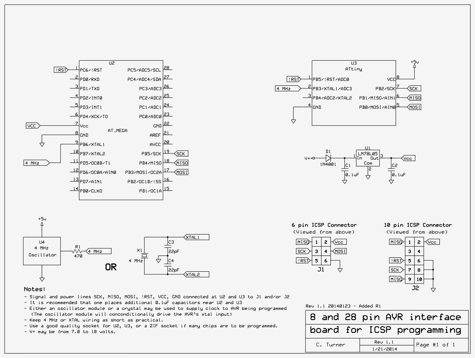
Figure 1, below is the result.

Figure 1:
The ICSP Interface board 8 and 28 pin AVRs built onto a 1-3/4" x 1-1/2" (approx. 45 x 40mm) prototype board.
The 6 pin ICSP connector may be seen along the right side of the board.
(Yes, I know that the label says "8 & 20" pins - I changed it after taking the picture...)
(Click on the image for a slightly larger version)
The Atmel AVR chips are quite popular these days, being the basis of many of the Arduino boards and variants, but they are also popular for "ground up" projects - that is, a custom design needing a microcontroller - the Ultimate 3 being just one example.  To reprogram the U3's processor I would need a 28 pin socket, but since there was room on the board I decided to include an 8 pin for the ATtiny chips as well should I decide to build something around one of those in the future.

In looking on the GoogleWeb I saw a plethora of diagrams showing how these chips would be connected to either a 6 pin or 10 pin ICSP connector, so I built  the board above (sans oscillator at first - more on that in a moment) and tried to read the chip's signature....

It didn't work.

Oops - I'd forgotten a power supply, as the AVRISP MkII programmer didn't supply power to the chip being programmed.  No problem: I threw a 78L05 and a pair of 0.1uF capacitors on the board so that I could supply a stable, clean source of 5 volts externally.  Connecting the programmer again it now read 5.1 volts via the ICSP connector.  I again tried reading the chip's signature.

It still didn't work.

Trying the programmer on an Arduino board I verified that it actually worked - and then I remembered that there was a very good chance that these AVRs would need a clock source in order to function.  Rummaging around in my collection of resonators I found a 3-lead 4.0 MHz ceramic resonator with built-in capacitors and plopped it onto the board.

Success!

For some reason, I decided that that wasn't enough:  I thought "What if the fuses on the chip were configured to take an external clock source and the device was not configured to an external crystal?" - could an AVR be configured to be that way - even during programming?  Rather than research that point I decided to completely circumvent the issue and put a 4 MHz "can" oscillator on the board instead of the resonator and connect it to the clock/crystal input pin of the AVR designated as "XTAL1" on each of the two sockets.

At the moment I have only a few AVRs with which to test:  One of them was configured to use a 20 MHz crystal while the other was set up to accept an external oscillator for the clock.  When originally tested with the 4 MHz ceramic resonator, the one configured to use the crystal did work in this circuit but the other one did not.  Once I changed to a 4 MHz oscillator module they could both be read and written.
 
Figure 2: 
 Schematic diagram of the AVR ICSP interface board
(Click on the image for a larger version)


In Figure 2, above, you can see the final result and some notes.

I find it quite interesting that while I could find the ICSP connections for the AVR all over the InterWeb (or is it GoogleFace?) I could find not one of them (at least in the first half dozen pages of results...) that actually made mention of the need for a clock source or a self-contained power supply!  The assumption seemed to be that anyone, anywhere, would include the ICSP connections on their project board, already and never have a need to program a "free-standing" chip.

While my programmer has only the 6 pin ICSP connector I dug up the 10 pin connector pinout for the convenience of someone else who might have that.  I also included in the notes the option of using either a ceramic resonator/quartz crystal OR a 4 MHz "can" oscillator.

Later, I decided to add R1 on the oscillator module's output - just in case the fuses on the processor had been set to cause this pin be a logic output as might be the case if the AVR's internal oscillator is used - in which case, it probably wouldn't need any external crystal or oscillator at all.  The 470 ohm resistor allows the line to be driven easily, but limit the current to a very safe value were it set to a 0 or 1.

Note: 
The actual frequency of the crystal, oscillator or resonator is not important, but it must be within the ratings of the processor being programmed at the operating voltage provided by the programming circuit.  Also, the programming clock speed - selectable in the programming software - must be no faster than 1/4th of the oscillator/crystal/resonator frequency.
The default of 250 kHz is used in the version of Atmel Studio that I was running.  Anything in the 1 MHz to 8 MHz range for a crystal, resonator or oscillator module is likely to work equally well.  If the AVR is configured to use a very slow internal oscillator, the programming software would need to have its programming clock frequency changed accordingly.

While I used a 78L05 for the voltage supply to the chip being programmed, about anything that provides a stable and clean source of 3.3-5.5 volts would probably work (you'd have to verify the operating voltage range of the processor that you are programming) and this could even include the use of 3 AA or AAA cells in series to get 3-5 volts, the exact voltage depending on the condition of the battery.

If you do use a battery to provide power for the processor during programming make sure that there is at least one 0.1uF capacitor located near-ish U2 and/or U3.  If you use the crystal can oscillator with a battery you will need to add an on/off switch, but if you chose to use the crystal or ceramic resonator, instead, you could forgo the switch - provided that you never left a processor in either the U2 or U3 socket when done!

Comment:
A switch may be a good idea, anyway as it is recommended that one removes the power before plugging in or unplugging the processor from its socket - but I will admit that I frequently don't bother doing that and have never had a problem... yet...
There are AVRs out there than those with 8 and 28 pins - and maybe even some 8 or 28 pin devices with pin-outs that don't match Figure 2, but the 8 and 28 pin versions for which the sockets are wired are the two sizes for which I expect to have immediate need.

One thing that the AVR ISP and this board cannot deal with is if the AVR's LVP (Low Voltage Programming) has been disabled.  If you configure an AVR such that this feature is disabled it is possible that you will need to seek out a programmer with "High Voltage Programming" to reset the fuse and re-enable LVP. 

My prototype board is only 1-3/4"x1-1/2" (approx. 45x40mm) so there wasn't really enough room to put anything on it other than what I did - and I was barely able to cram the 4 MHz can oscillator on the board as it was!

[End]

This page stolen from ka7oei.blogspot.com

Tuesday, January 7, 2014

RIP Gretchen cat

In the summer of 2001, in the courtyard of the apartment complex where my older brother lived at the time a feral mother cat had a litter of 4 kittens:  Two males and two females.  When they were about 5-6 weeks old I got one of them (which was named Oscar) and a co-worker of mine who'd come along got one of the female kittens.  Both were somewhat sickly at the time and I while managed to nurse Oscar back to health, the female kitten died.  A week or so later we went back and he was able to capture the other male, leaving a female kitten there.

Some months later - October, I believe - my brother reported that the remaining female kitten was still there and I was goaded into coming over.  I had two cats already:  Oscar, and a then 4-year old Siamese named Thomas, and I was somewhat reluctantly convinced to adopt another cat.  Somewhere we found a fish net and managed to catch the small, wild, hissing furball and stuff her in a pet carrier, everyone involved getting scratched in the process.  Taking her to the vet she was pronounced healthy and in due course she got both vaccinations and "fixed."  Near the beginning of all of this, someone - I'm not sure who - decided that her name would be Gretchen.

For the first few months that I had her she was little but an elusive shadow that I would only occasionally see around the house, but she slowly became bolder, eventually getting brave enough to leap onto the bed at night, demand to be petted for a few minutes and then wander off somewhere else to sleep - and there were many days in the beginning when that would be the only time that I would see her.

Unfortunately, she and her brother, Oscar, never got along and pretty much avoided each other, occasionally getting into brief, noisy fights and very occasionally I'd find that one of them had been contacted by the sharp claws of the other.  Gradually she became attached to me and would usually park herself somewhere in the same room is I - usually just out of sight until she'd suddenly hop into my lap and curl up, purring while I scratched her neck.

Today, however, I had to let go of Gretchen the cat.

Late last week she was off her food and seemed lethargic - a rather sudden change from her normal behavior of just a few days before.  Seeing that she was dehydrated I gave her about 150 milliliters of ringers lactate subcutaneously (I had this paraphernalia on hand from a previous health scare with Oscar:  I would recommend that anyone with aging cats obtain this from a vet and learn how to use it!) and called the vet as soon as its office opened the next morning, a Saturday.

Upon examination the news was not good:  She had rapidly and recently acquired some gum lesions and her blood work showed that her kidneys were nearly nonfunctional and she also had an infection which the vet said was likely a result of her kidney problems rather than the cause.  Despite being rather doubtful of the ultimate outcome, the vet gave me some antibiotics and more ringers lactate, sending me home with her.

It would not surprise you to know that despite the antibiotics and infusions she did not get any better.  On Saturday she ate a bit of the special food that the vet had given me, a bit less on Sunday and nothing on Monday.

This morning I found her in the room where the waterbowl and litter box are, lying weakly on the carpet and she could barely stand when coaxed to do so.  At such this point a difficult decision had to be made - and you already know that that was.

I called the vet, made an appointment, went in with a cat, stayed with her until after she passed away and left with an empty pet carrier.

I do still have Oscar, Gretchen's brother and the Siamese cat, Thomas who is now approaching 18 years old.  Both of them have their problems:  Oscar had transient renal failure two years ago and somehow recovered (for now...) while Thomas is suffering largely from old age.  Even though she only appeared from her hiding places when I was home alone and was very particular in deciding when she wanted my attention, I will miss this cat.

Gretchen the cat - a picture taken on January 5, 2014, two days before she died.

Afterward:

In the months that followed, I have lost the other two cats mentioned above.  Thomas died in May due to old age and in July, Oscar, Gretchen's sibling, died of complications of renal and hepatic failure.  Later that year I got another cat from my niece - a 16 year old grimalkin:  I had her for about two and a half years before she also succumbed to old age in July of 2016.

At the moment I have one cat - Izzy - a fuzzy, mixed-breed (mostly) Japanese bobtail female that I got from my niece in February or March when she moved into a place where should could not have pets.  A bit of a derp, she's an affectionate cat, but not bonded to any particular person like the other three cats - but still company, nonetheless.

[End]

This page stolen from ka7oei.blogspot.com

Tuesday, December 31, 2013

A simple inverter for driving neons/nixies using Radio Shack parts

I was visiting a friend of mine a few weeks to who was helping me repair the Model H horn on my old Atwater Kent 20C receiver.  This radio and horn lives in my office at work and one day, I heard a thud as the horn portion spontaneously broke off from the base and landed on the carpeted floor.  Inspection showed that the original cast aluminum part had a lot of voids and impurities and it finally broke - after nearly 90 years!  To fix it, we drilled out the aluminum and I fitted a steel sleeve that he'd machined and used metal epoxy to secure it - a very strong and (pretty much) invisible fix!

But I digress...

After the repair we wandered into his ham shack to talk for a while.  He is a collector of old, unbuilt kits and has a soft spot for the Radio Shack "P-Box" kits from the late 60's and early 70's.  For a list of those kits - along with much of the documentation, look here:

http://my.core.com/~sparktron/pbox.html

In particular he was interested in replicating the "Goofy Light" kit - see item 28-130 on the above link.

This kit is pretty simple:  A one-transistor oscillator along with a transformer produces 100-ish volts that power a series of neon lights.  Depending on how they are wired, they will produce a "chase" sequence or just blink randomly.

To replicate this identically would have required getting two parts that would likely be difficult to find:  A 2SB54 PNP germanium transistor and 1k-200k audio transformer.  Being practical, there was really no need to use a PNP germanium transistor in this:  A 2N3904 or similar NPN silicon would be just fine - but the audio transformer was another matter!

The actual impedance of the transformer wasn't as important as the turns ratio - and for the 1k : 200k transformer that would be the square root of the impedance ratios, as in:

sqrt(200/1) - 14.142 : 1 turns ratio.

Being that the turns ratio is one of the factors that determines the voltage transformation, it was fairly important that we find something that was sort of close.

If the waveform had been sinusoidal, a (theoretical) 6 volt input would produce about 85 volts of AC on the output.  Fortunately (!) for us, it's not quite that simple.  While the transistor/circuit losses would likely reduce the drive level to 2-3 volts or so, the waveform was likely to be anything but sinusoidal - more likely, it would be rather "spikey" as the transistor snapped on - then off again and it would be this "ugly" waveform that would likely have spikes and ringing that would produce voltages far in excess of that determined by just the turns ratio!

In searching the online Mouser-Key catalogs we found a number of possible candidates for substitution, including the Mouser 42TM-114RC which was a 20 ohm to 4.6k (15.2 : 1 ratio)  transformer with center taps on both the primary and secondary and it was readily available for just $2.74.  While this transformer would probably work just fine (the absolute impedance isn't terribly important in this application) he was interested in what might be on-hand locally.

At some point he'd been to Radio Shack and picked up a couple of their 273-1380 8 ohm to 1k (center-tapped) audio transformers and we decided to see if we could make that work.

The obvious difference - aside from the absolute impedance values and the lower turns ratio (this transformer had an 11.1 : 1 ratio) was that it did not have a tapped "primary" - and it was this tap that had provided the feedback path in the original P-Box circuit.  It did have a tapped secondary and I wondered if I could make that work so I threw together the following circuit using flying leads on the workbench.

A word of warning:
  • The voltages that can be generated by this circuit could potentially be lethal, so be very careful.  (You are unlikely to get more than a "tickle" or a slight bite, but be aware!)
  • It is possible that you'll blow up a transistor or two if you experiment with parts values and output loading.  You may also ruin a transformer, so pay attention to anything that is getting hot!

For this first version, I'd omitted Cfilt and Ca, using a 10k resistor for Ra and a 2N3904 for Q1.

Figure 1.
A simple circuit using a transformer and transistor to produce fairly high voltages.
The noted colors are for the Radio Shack 273-1380 transformer and indicate phasing:  If the phasing is
incorrect, the circuit may not oscillate!
(V+ is connected at the junction of the Red and Blue wires.)


Amazingly, it worked the first time, lighting the NE-2 type lamp attached to it - this, with a power supply of just 7 volts.  While the circuit worked, the current consumption was a bit higher than we would have liked - around 50-60mA at 7 volts - not terribly efficient, but then again, it was not at all bad for such a simple circuit on the first try!

Changing R1 to 47k, the circuit still worked fine and pulled only about 15-20 mA and the output voltage was a bit lower - still able to (just barely) light the neon at 7 volts, but brightly illuminating it at 12 volts.


After I got home from his place I decided to experiment with the circuit a bit more and in so-doing I put the 'scope on the output lead using the version without any capacitors and Ra = 10k and with the power supply at 6 volts, getting the waveform below:

Figure 2:
An example of the waveform being output from the transformer.

As you can see, the waveform is very "spiky" (to be expected) with the peak part being mostly at a negative voltage (e.g. below zero, the dashed line in the middle.)  With just a 6 volt DC supply the total waveform was about 226 volts peak-to-peak (more or less) with the oscillation frequency being about 2 kHz and the current consumption being about 50mA.

For the heck of it I decided to reconfigure the circuit as follows:

Figure 3:
 A reworked version of the same circuit as in Figure 1.  It produces a waveform that is essentially
an upside-down version of that in Figure 2, but at lower voltage since we have but half of the
secondary winding to produce an output voltage.
(V+ is connected at the Red/Green wire connection)


The result of this was a circuit that produced a lower peak-to-peak voltage than that in Figure 2 because only half of the secondary was referenced to ground via the center-tap and the power supply.  The waveform also looked similar to the one in Figure 2,  but upside-down - that is, the spike was positive-going.  It also drew a bit less current - around 35 mA.  (Cfilt and Ca were omitted and Ra was still 10k).

More experimentation with the circuit in Figure 1:

Because I was interested in the higher voltage I rewired the circuit back to the configuration in Figure 1 and did more testing, this time adding the following circuit to the output:

Figure 4:

This simple circuit converter that will handily convert the negative-going  portion of the waveform to positive and then add it to the positive-going part, which meant that with the circuit in Figure 1 operating from 6 volts you could get an unloaded voltage of over 200 volts DC.

For this testing I added Ca, using a 0.1uF capacitor and when I did this the quiescent current of the circuit dropped from 50-60mA to around 15-20mA when operating from 6 volts.  The output waveform looked about the same as that in Figure 2 but the oscillation frequency was now closer to 1 kHz.  When using the circuit in Figure 4 the voltage was slightly lower - but this was probably due to the high voltage spike occurring less often and keeping the capacitor (C2) charged in spite of the 10 Megohm load of the voltmeter.

For this circuit, C1 and C2 should be at least 0.1uF and rated for 250 volts or more while D1 and D2 should be high voltage diodes such as the 1N4004 or 1N4007 - or, better yet, a high-speed, high-voltage switching diode such as the RGP15G.

The actual values of C1/C2 depend on your load and how much ripple you can tolerate.  At 1-2 kHz, C1/C2 = 0.1uF will produce a fairly clean supply if you are only pulling a few hundred microamps.  For testing I used 0.22 uF for C1 and 0.47 uF for C2.  If you want a "cleaner" supply (i.e. less ripple) than the value of C2 can be increased further.

I decided to do a bit more testing with this circuit at different loads and supply voltages and came up with the following results, measuring the voltage across C2.  (Ra = 10k, Ca = 0.1uF):

6 Volts:
14k load - 52 volts output (3.7mA, approx. 190 mW)
100k load - 102 Volts output (1.02 mA, approx. 104 mW)
10 Meg load - 220 Volts output (22uA, approx. 5 mW)

10 Volts:
14k load - 63 Volts output (4.5mA, approx. 283 mW)
100k load - 155 Volts output (1.55 mA, approx. 240 mW)
10 Meg load - 325 Volts output (32.5 uA, approx. 10.6 mW)

15 Volts:
14 k load - 72 Volts output (5.1 mA, approx. 370 mW)
100k load - 234 Volts output (2.34 mA, approx. 548 mW)
10 Meg load - 460 Volts output (46 uA, approx. 21 mW)

Notes:
  • The values in parentheses indicate the current flowing through the resistor being tested and the total power being dissipated by it.
  • A 14k load was chosen since this was the first resistor that I'd grabbed while the 10 Meg load was that of the meter that I was using to measure the voltage.

Using a high-current transistor:

For the heck of it I changed Q1 from a 2N3904 - a rather generic transistor - to a KSD5041, a specialized, high-current transistor designed specifically for photoflash use:  As compared to the 2N3904's 600 mA capability, the KSD5041 can handle about 5 amps!

As expected, the circuit drew more current when unloaded - around 70 mA or so, but I got much more voltage on the output when operating it from 6 volts:

14k load - 65 volts output (4.6 mA, approx. 297 mW)
100k load - 140 volts output (1.4 mA, approx. 196 mW)
10 Meg load - 500 Volts output (50 uA, approx. 25 mW)

In putting the 'scope on the output the waveform looked much like that in Figure 2, but the spike was much "sharper" and taller - no doubt due to the transistor turning on more firmly and allowing a higher magnetic flux to build up in the transformer.  In looking at the voltage across the collector of Q1, I noted that the waveform peaked up to about 55 volts - somewhat above the 40 volt rating of the KSD5041 transistor!

When I raised the power supply voltage to 10 volts I measured over 650 volts on the output before it started to sag and was accompanied by a dramatic surge in power supply current.  While the circuit still worked, the current was still high when I returned the voltage back to 6 volts and upon pulling the transistor and testing it, its current gain was very low, indicating that it had been damaged - unsurprising since I had already been seeing 55 volts on its collector when I'd been running at just 6 volts!

What's Cfilt for?

You'll notice "Cfilt" on the schematic diagrams.  If you are operating this circuit from a battery with very short leads, you can probably leave this capacitor off since the battery itself - and the short wires - will have a fairly low impedance, an important property for this circuit to function well.

If you are running this from a power supply - particularly one that is shared with other circuits - Cfilt should be used.  A suggested value for this capacitor is 47-220 uF and "low ESR" capacitors are recommended for this.  A word of warning, however:  Even with a good quality filter capacitor this circuit is likely to put noise on the power supply!

Additional comments:

You may substitute a PNP transistor (such as a 2N3906) for Q1 if  you reverse the power supply voltage,  If you do so you will also get a voltage waveform that is an upside-down version of the one in Figure 2.

If you need very low current at a higher voltage you can use just a simple, series diode and filter capacitor, taking advantage of the high voltage "spike" that is produced.

What is this circuit good for?

This circuit can be used for several things:
  • High voltage supply for Neon indicators.
  • It can also be used as the high voltage source for Nixie tubes - provided that both the power dissipation of the transformer/transistor and voltage under load are taken into consideration.
  • Powering of electroluminescent strips including the so-called "EL Wire" - although the cheap inverters sold for that purpose will likely work better!
  • The generation of a plate supply for low-power vacuum tube projects
If you want even more voltage there are several options you can increase the voltage by adding more capacitor/diode stages.  For more information on high voltage multipliers, look at the following web page:

http://en.wikipedia.org/wiki/Voltage_multiplier  (link)

In theory, it should be possible to get thousands of volts from this circuit but remember that as you go up in voltage, the amount of current that you can pull will go down!

Final words:

This circuit is not particularly efficient but with a bit more work and complexity, it could probably be made to be a bit better.  Its biggest advantage is that it uses parts that you are likely to find at your local Radio Shack and in your junk parts pile!

[End]

This page stolen from ka7oei.blogspot.com

Sunday, November 24, 2013

Improving the bass response of a (cheap) subwoofer amplifier system by *reducing* its bass response

Several weeks ago I happened to be at a local electronics type store (I'll admit it, it was Radio Shack!) and they had on clearance - for a pretty good price - a nice-looking set of computer speakers (40-288).  This set consists of a pair of small-ish speakers for the upper-bass, midrange and highs along with a single, larger-ish "subwoofer" for bass.  I didn't get these for a computer, but to reinforce the sound from a small, flat-screen TV that I have near my electronics workbench that has appallingly bad internal speakers.


Figure 1:
The inexpensive speaker/subwoofer system.
Click on the image for a larger version.
Upon connecting them to the TV I was immediately struck by the fact that they sounded OK - except that the bass sounds were frequently breaking up at moderate volumes during musical bass notes and the sound of explosions - which are very common on TV.  I flipped the subwoofer on end and noted that, as expected, it was a ported enclosure (see Figure 3) which is typical for low-frequency speakers, large and small.

Knowing the size of the speaker's enclosure - roughly a cube that is 11.5cm on a side internally - and also the diameter of the speaker itself - about 6cm - I also knew that it could not provide extremely low bass-frequency response.  Based on a guess, I figured that its usable frequency response would extend down to roughly 125 Hz or so:  You just can't get much lower than that with reasonable efficiency using a simple ported box and (inexpensive) bass driver that is that small!

The problem:

The problem with the design of this subwoofer is one that is commonly seen:  If the system is "asked" to amplify frequencies well below the range that may be reproduced by the bass driver and its enclosure, several things are likely to happen:
  • Power will be wasted with the speaker's cone flapping about and frequencies well below those in which it is likely to be able to move air efficiently.  What this means is that instead of working on frequencies that can be reproduced, much of the amplifier's power will be used up (e.g. wasted) on these other "useless" (to the speaker, anyway) frequencies!
  • The speaker itself may be damaged.  On a ported enclosure such as this, driving with too low a frequency, the speaker just can't transfer energy to the air mass efficiently and in so doing, its cone moves too "easily."  If this happens the speaker's excessive cone excursions can cause physical damage and heat can even build up in the voice coil assembly.  The latter is a bit less likely to happen with this small of a speaker and with the modest amplifier power level involved, but it is still possible.
  • It will sound terrible.  With the amplifier clipping, trying to amplify too much low-frequency range content that cannot be reproduced, and with the speaker itself flapping about trying to reproduce the low-frequency sound, you can end up with distortion, popping and buzzing.
Connecting it to an audio generator I swept from about 1 kHz down to 10 Hz or so and as expected, the crossover point from the smaller speakers to the subwoofer was in the general area of 200 Hz - not sharp, but definitely there.

I also saw that the speaker was still being fed power when I got down below 10 Hz, at which point uselessly flapping about as there was no way that it could reasonably be expected to efficiently transduce energy at that frequency - and that was the reason why it sounded like it was breaking up on low bass notes!  Careful observation revealed that the amplifier seemed to have a slight "peaking" effect in the area of 100-200 Hz - likely done to slightly emphasize the frequencies best conveyed by the subwoofer.  (I didn't reverse-engineer the circuit enough to determine if this was intentional or not.)

The "fix"

Figure 2:
 Bottom-side location of the capacitor to be changed along
with the added 10k resistor.
Click on the image for a larger version.
Popping apart the satellite speaker that contained the amplifier I started poking around with an oscilloscope while varying the frequency of the audio generator and quickly found where the wipers of the dual volume control went over to a pair of surface-mount 3.6k resistors and the audio from the left and right channels were combined ("3R1" and "3R2" in Figure 2).  I then followed the audio through a 2.2 uF coupling capacitor (mounted on the other side of the board) and then to the input of the audio amplifier for the subwoofer - a stereo chip configured to drive the subwoofer in bridge mode to achieve maximum power power output for the supply voltage.

Note:  I didn't remove the heat sinks, so I don't know which audio amplifier chips are used in this speaker system.

At this point something struck me:  In comparing with the oscilloscope, the audio level "before" and "after" the 3.6k resistors used to combine the left and right channel I could see that there was practically no difference, indicating that the amplifier itself minimally loaded the audio line beyond that point.  Having just followed this signal path I also knew that there was nothing that limited the low frequency response of the amplifier to something within a reasonable range of what the speaker itself was likely to be able to reproduce!

To satisfy my hunch I replaced the 2.2uF capacitor with a 0.022uF capacitor and noted that it only just started rolling off the frequency response below 100 Hz, indicating that the amplifier's input impedance was likely in the range of 50-100k, so with the 2.2uF coupling capacitor, the amplifier was going to amplify signals down to less than 1 Hz with minimal rolloff! What I needed to do was to limit the frequency range of the amplifier to something more reasonable in terms of what the speaker was likely to be able to reproduce!

To do this, there are two reasonable options:
  • Build a nice, multi-pole high pass filter that will sharply cut off the audio below a certain frequency - say, 100 Hz.  This would require either a transistor or two or an op amp along with a handful of other components and would be built upon a small circuit board that was added into the enclosure and connected inline with the subwoofer amplifier's audio path.
    Figure 3:
    The bottom side of the subwoofer cabinet showing
    the driver and port.  If you throw too-low a frequency at this sort
    of speaker it just thrashes around and doesn't really
    produce much sound.  It's always  best to send only those frequencies
    to the sub's amplifier that the speaker will be able to reproduce!
    Click on the image for a larger version.
  • Just kludge it and make a simple R/C high pass filter.  This wouldn't as sharply cut off the low frequencies, but it would likely do the job of preventing ridiculously low frequencies from getting to the amplifier and cause it to waste effort!
I chose the latter.

In poking around on the audio input pin of the amplifier I saw that there was no DC offset, so I temporarily connected a 10k resistor between it and what appeared to be a nearby ground - at least, it was where there was a capacitor connected across the input to roll off the high frequencies above which the subwoofer was not supposed to amplify.  Temporarily tacking the 2.2uF back into place, I saw with the oscilloscope that the 10k resistor made almost no difference the subwoofer's output level and that its output remained clean.  I then made the 10k resistor a permanent part of the circuit, soldering it on the bottom side of the board as can be seen in Figure 2.

Grabbing a calculator I crunched a few numbers and decided that a 0.1uF capacitor (a nice, round value) in place of the original 2.2uF capacitor would be worth trying as it, in conjunction with the 10k resistor, would provide a -3dB roll off frequency of about 159 Hz - a fact confirmed using the oscilloscope and audio generator.  With the amplifier's slight "peaking" noted above, the power wasn't down by 6dB at 160 Hz, but closer to 100 Hz at the -6dB point.  (I used a plastic capacitor rather than a ceramic capacitor because the latter would have had terrible temperature stability.)

Feeding some music with a lot of low bass into the speaker system, it seemed to sound just fine:  Reasonable low-frequency response and no obvious distortion - even at fairly high audio levels.  Tacking the 2.2uF capacitor back into place the perceived bass response improved slightly, but now the audio amplifier was breaking up badly with obvious clipping and distorting as before.  Taking the 2.2uF capacitor off again I tacked another 0.1uF across the first (for a total of 0.2uF) to set the hypothetical -3dB frequency to about 80 Hz and could hear a very slight increase in amplitude of the bass notes and a bit of occasional clipping at fairly high volume, but it didn't seem to be worth it to have the extra capacitor on there so I left it at just 0.1uF.

Figure 4:
The completed modifications - along with the added
heat sink material.  This is just a scrap of copper - probably from a
piece of water pipe - that I cut down the side, cut tabs to match the chip's
"heat sink" and ground pins on the foil side of the circuit board, and then,
using a very hot soldering iron to get the job done quickly, attached
it to the circuit board.  The foil side of the circuit board faces up
within the box so the heat actually radiates better this way!
Click on the image for a larger version.
While having the unit apart I noticed that the heat sink of the subwoofer's amplifier chip was far too hot to touch after a few minutes of abuse from the signal generator.  Typically, these sorts of chips have built-in thermal protection, so it was not too likely to be damaged by getting hot, but this thermal protection often works by causing the amplifier to cut its power back - usually causing distortion.

To be sure, my reducing the frequency response of the amplifier greatly reduced that amplifier chip's thermal load, but I decided to solder a bit of scrap copper to the heat sink fins on the "bottom" side of the board (which actually faces up when the board is installed) to increase its heat dissipation ability.

Now, with the very low frequencies eliminated from the amplifier it could put more power into reproducing those low frequencies that were well within its capabilities without wasting it on frequencies that were too low.

Putting the entire thing back together, it now works fine in its intended role:  As a half decent sounding speaker system for the small TV!

[End]

This page stolen from ka7oei.blogspot.com