Showing posts with label oscillator. Show all posts

Sunday, October 1, 2023

Resurrecting my FE-5680A Rubidium frequency reference

Fig 1:
The Hammond 1590 aluminum case
housing the FE-5860A rubidium osc-
oscillator and other circuitry - the
markings faded by time and heat.
Click on the image for a larger version.
Recently I was getting ready for the October 14, 2023 eclipse, so I pulled out my two 10 MHz rubidium frequency references (doesn't everyone have at least one?) as I would need an accurate and (especially) stable frequency reference for transmitting:  The details of what, why and how will be discussed in a post to be added in the near future.

The first of these - my Efratom LP-101 - fired up just fine, despite having seen several years of inactivity.  After letting it warm up for a few hours I dialed it in against my HP Z3801 GPSDO and was able to get it to hold to better than 5E-11 without difficulty.

My other rubidium frequency reference - the FEI FE-5680A - was another matter:  At first, it seemed to power up just fine:  I was using my dual-trace oscilloscope, feeding the 'Z3801 into channel 1 and the '5680A into channel 2 and watching the waveforms "slide" past each other - and when they stop moving (or move very, very slow) then you know things are working properly:  See Figure 2, below, for an example of this.

That did happen for the '5680A - but only for a moment:  After a few 10s of seconds of the two waveforms being stationary with respect to each other, the waveform of the '5680A suddenly took off and the frequency started "searching" back and forth, reaching only as high as a few Hz below exactly 10 MHz and swinging well over 100 Hz below that.

My first thought was something along the lines of "Drat, the oven oscillator has drifted off frequency..."

Fig 2:
Oscillogram showing the GPS reference (red)
and the FE-5680A (yellow) 10 MHz signals
atop each other.  Timing how long it takes for the
two waveforms "slide" past each other (e.g. drift
one whole cycle) allows long-term frequency
measurement and comparison.
Click on the image for a larger version.

As it turns out, that was exactly what had happened.

Note: 

 I've written a bit more about the aforementioned rubidium frequency references, and you can read about them in the links below:

Oscillator out of range

While it is the "physics package" (the tube with the rubidium magic inside) that determines the ultimate frequency (6834683612 Hz, to be precise) it is not the physics package that generates this frequency, but rather another oscillator (or oscillators) that produce energy at that 6.834682612 GHz frequency, inject it into the cavity with the rubidium lamp and detect a slight change in intensity when it crosses the atomic resonance.

In this unit, there is a crystal oscillator that does this, using digital voodoo to produce that magic 6.834682612 GHz signal to divine the hyperfine transition.  This oscillator is "ovenized" - which is to say, the crystal and some of the critical components are under a piece of insulating foam, and attached to the crystal itself is a piece of ceramic semiconductor material - a PTC (positive temperature coefficient) thermistor - that acts as a heater:  When power is applied, it produces heat - but when it gets to a certain temperature the resistance increases, reducing the current consumption and the thermal input and the temperature eventually stabilizes.

Because we have the rubidium cell itself to determine our "exact" frequency, this oven and crystal oscillator need only be "somewhat" stable intrinsically:  It's enough simply to have it "not drift very much" with temperature as small amounts of frequency change can be compensated, so neither the crystal oven - or the crystal contained within - need to be "exact".

Fig 3:
The FE-5680A itself, in the lid of the
case of the 1590 box to provide heat-
sinking.  As you can see, I've had this
unit open before!
Click on the image for a larger version.
What is required is that this oscillator - which is "pullable" (that is, its precise frequency is tuned electronically) - must be capable of covering the exact frequency required in its tuning range:  If this can't happen, it cannot be "locked" to the comparison circuitry of the rubidium cell.

The give-away was that as the unit warmed up, it did lock, but only briefly:  After a brief moment, it suddenly unlocked as the crystal warmed up and drifted low in frequency, beyond the range of the electronic tuning.

Taking the unit apart I quickly spotted the crystal oscillator under the foam and powering it up again, I kept the foam in place and watched it lock - and then unlock again:  Lifting the foam, I touched the hot crystal with my finger to draw heat away and the unit briefly re-locked.  Monitoring with a test set, I adjusted the variable capacitor next to the crystal and quickly found the point of minimum capacitance (highest frequency) and after replacing the foam, the unit re-locked - and stayed in lock.

Bringing it up to frequency

This particular '5680A is probably about 25 years old - having been a pull from service (likely at a cell phone site) and eventually finding its way onto EvilBay as surplus electronics.  Since I've owned it, it's also seen other service - having been used twice in in ground stations used for geostationary satellite service as a stable frequency reference, adding another 3-4 years to its "on" time.

As quartz crystals age, they inevitably change frequency:  In general, they tend to drift upwards if they are overdriven and slowly shed material - but this practice is pretty rare these days, so they seem to tend to drift downwards in frequency with normal aging of the crystal and nano-scale changes in the lattice that continue after the quartz is grown and cut:  Operating at elevated temperature - as in an oven - tends to accelerate this effect.

By adjusting the trimmer capacitor and noting the instantaneous frequency (e.g. adjusting it mechanically before the slower electronic tuning could take effect) I could see that I was right at the ragged edge of being able to net the crystal oscillator's tuning range with the variable capacitor at its extreme low end, so I needed to raise the natural frequency a bit more.

If you need to lower a crystal's frequency, you have several options:

  • Place an inductor in series with the crystal.  This will lower the crystal's in-circuit frequency of operation, but since doing so generally involves physically breaking an electrical connection to insert a component, this is can be rather awkward to do.
Fig 4:
The tip of the screwdriver pointing at the added 2.2uH
surface-mount inductor:  It's the black-ish component
at sort of a diagonal angle, wired across the two
crystal leads.
Click on the image for a larger version.
  • Place a capacitor across the crystal.  Adding a few 10s of pF of extra capacitance can lower a crystal's frequency by several 10s or hundreds of ppm (parts-per million), depending on the nature of the crystal and the circuit.

Since the electrical "opposite" of a capacitor is an inductor, the above can be reversed if you need to raise the frequency of a crystal:

  • Insert a capacitor in series with the crystal.  This is a very common way to adjust a crystal's frequency - and it may be how this oscillator was constructed.  As with the inductor, adding this component - where none existed - would involve breaking a connection to insert the device - not particularly convenient to do.
  • Place an inductor across the crystal.  Typically the inductance required to have an effect will have an impedance of hundreds of ohms at the operating frequency, but this - like the addition of a capacitor across a crystal to lower the frequency - is easier to do since we don't have to cut any circuit board traces.
With either method of tweaking the resonance of the oscillator circuit, you can only go so far:  Adding reactance in series or parallel will eventually swamp the crystal itself, potentially making it unreliable in its oscillation - and if that doesn't happen, the "Q" is diminished, potentially reducing the quality of the signal produce and furthermore, taking this to an extreme can reduce the stability overall as it starts to become more temperature sensitive with the added capacitor/inductor than just the crystal, alone.

In theory, I could have placed a smaller fixed capacitor in series with the trimmer capacitor  - or used a lower-value capacitor - but I chose, instead, to install a fixed-value surface-mount inductor in parallel with the crystal as it would not require cutting any traces.  Prior to doing this I checked to see if there was any circuit voltage across the crystal, but there was none:  Had I seen voltage, adding an inductor would have shorted it out and likely caused the oscillator to stop working and I would have either reconsidered adding a series capacitor somewhere or, more likely I would have placed a large-value (1000pF or larger) capacitor in series with the inductor to block the DC.

"Swagging" it, I put a 2.2uH 0805 surface-mount inductor across the crystal and powered up the '5680A and after a 2-3 minute warm-up time, it locked.   After it had warmed up for about 8 minutes I briefly interrupted the power and while it worked to re-establish lock I saw the frequency swing nearly 100 Hz below and above the target indicating that it was now more less in the center if its electronic tuning range indicating success!  As can be seen from Figure 4, there is likely enough room to have used a small, molded through-hole inductor instead of a surface-mount device.
Fig 5:
The crystal is under the round disk (the PTC
heater) near the top of the picture and the
adjustment capacitor is to the right of the
crystal.
Click on the image for a larger version.

With a bit of power-cycling and observing the frequency swing while the oscillator was hot, I was able to observing the electronic tuning range and in so-doing, increase the capacitance of the trimmer capacitor very slightly from minimum indicating that I now had at least a little bit of extra adjustment room - but not a lot.  Since this worked the first time I didn't try a lower value of inductance (say, 1uH) to further-raise the oscillator frequency, leaving well-enough alone.

Buttoning everything back up and putting it back in its case, everything still worked (always gratifying!) and I let the unit "burn in" for a few hours.

Comparing it to my HP Z8530 GPS Disciplined oscillator via the oscilloscope (see Figure 2) it took about 20 minutes for the phase to "slide" one entire cycle (360 degrees) indicating that the two 10 MHz signal sources are within better than 10E-10 of each other - not too bad for a device that was last adjusted over a decade ago and as seen about 15000 operational hours since!
 
* * *
 
Follow-up:  A few weeks after this was originally posted I had this rubidium reference with me at the October, 2024 Eclipse event as a "hot standby", its frequency being compared to the LPRO-101 - which was the active, on-the-air unit - using an oscilloscope.
 
This (repaired) unit fired up and locked within 5 minutes at the cool (45F/7C) ambient temperature and remained stable for the several hours that it was powered up.
 
I used this unit again form the April, 2024 Eclipse - this time, from a location in central Texas and, again, it worked perfectly.

* * * * *
 
This page stolen from ka7oei.blogspot.com
 
[END]
 

Saturday, March 4, 2023

Injection locking cheap crystal "can" oscillators to an external source

Figure 1:
The two generic "can" oscillators tested - both having been
found in my "box of oscillators".
Click on the image for a larger version.

Sometimes one comes across a device with one of those cheap crystal "can" oscillators that is "close" to frequency - but not close enough.  Perhaps this device is used in a receiver, or maybe it's used for clock generation or clock recovery. Such oscillator are available on a myriad of frequencies - although too-often not exactly the right one!

What if we want to "nail" this oscillator to an external (perhaps GPS) reference?  If this oscillator were variable, this task would be simplified, but finding a "VCXO" (Variable-Control Crystal Oscillator) on the frequency of interest is sometimes not even possible.

What if there were a way to externally lock a bog-standard crystal oscillator to an external source?

To answer this question, I rummaged through my box of crystal oscillators (everyone has such a box, right?) and grabbed two of them:  A standard 4 MHz oscillator and a 19.440 MHz oscillator that has an "enable" pin.

Comment:  

This article refers to standard, quartz crystal oscillators and not MEMs or "Programmable" oscillators where the internal High-Q resonating element likely has no direct relationship with the synthesis-derived output frequency.

Injection locking

This is what it sounds like:  Take a signal source of the desired frequency - typically very close to that of the oscillator that you are trying to nail to frequency - and inject it into the circuitry to lock the two together.

This technique is ancient:  It accounts for the fact that a (wobbly) table of pendulum-type metronomes set "close" to the same tempo will eventually synchronize with each other, and it is the very technique used in the days of analog TV to synchronize their vertical and horizontal oscillators to the sync signals from the incoming signal.

It's still used these days, one notable example being the means by which an Icom IC-9700's internal oscillator may be externally locked to an external 49.152 MHz source (see: http://www.leobodnar.com/shop/index.php?main_page=product_info&products_id=352 ) - and this is done by putting a known-stable source of 49.152 MHz "very near" the unit's built-in oscillator.

Injection-locking a discrete-component crystal oscillator is relatively simple:  It's sometimes just a matter of placing a wire near the circuitry (e.g. a "gimmick" capacitor) with the resonant element (e.g. near the crystal or related capacitors) and the light capacitive coupling will cause it to "lock" to the external source - as long as it's "close" to the oscillator's "natural" frequency.

Getting a signal inside the oscillator

Injection locking often needs only a small amount of external signal to be applied to the circuit in question - particularly if it's inserted in the feedback loop of the resonant circuit, but what about a "crystal can" oscillator that is hermetically sealed inside a metal case?

Figure 2:
Schematic depiction of power supply rail
to get the external signal "into" the can.
Click on the image for a larger version.
Because, in many cases, opening the can would compromise the seal of the oscillator and expose the quartz element to air and degrade it, this isn't really an option.  Another possibility would be to magnetically couple an external signal into the circuitry, but owing to a combination of its small size and the fact that these devices are typically in ferrous metal cans, this isn't likely to work, either.

So what else can one do to get a sample of our external signal inside?

Power rail injection

The most obvious "input" is via the power supply rail.  Fortunately - or unfortunately, depending on how you look at it - these oscillators often have built-in bypass capacitors on their power rails, putting a low-ish impedance on the power supply input - but this impedance isn't zero. 

Figure 3:
Top - The signal riding on the voltage rail
Bottom - The locked output of the oscillator
Click on the image for a larger version.
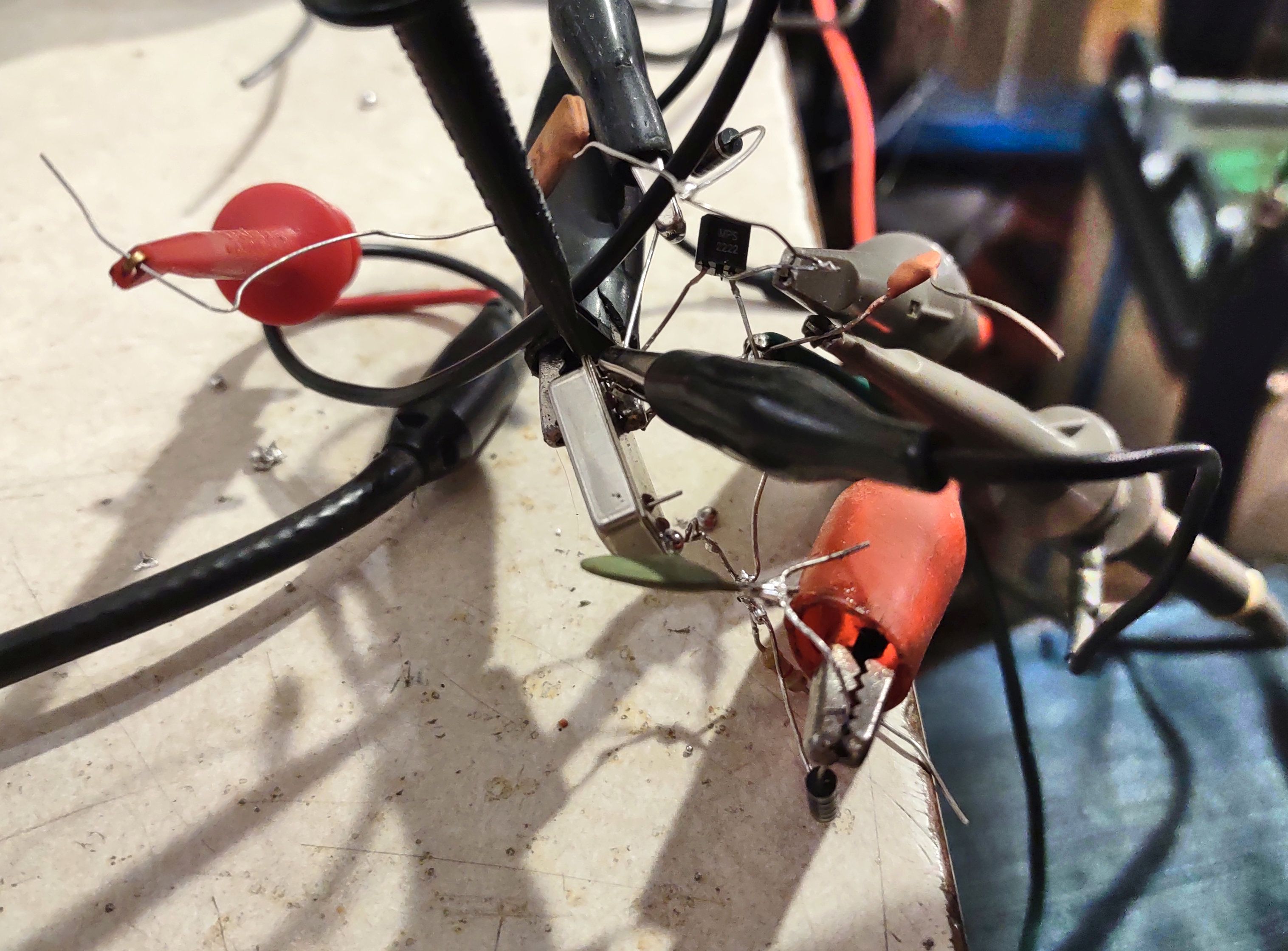
A simple circuit to do this is depicted in Figure 2.  The way it works is by decoupling the power supply via L1 and C1 and heavily "modulating" it with the signal to be locked with Q1.  For the test circuit seen in Figures 2 and 4, L1 and L2 were 10uH molded chokes, C1 and C2 were 0.1uF capacitors and Q1 was a 2N3904 or similar NPN transistor.  

When an external signal is applied to Q1 via C2 (I used +13dBm of RF from a signal generator) Q1 will conduct on the positive excursions of the input waveform, dragging the power supply voltage to the oscillator down with it.  With this simple circuit, Q1 has to dissipate quite a bit of power (the current was about 500 mA) and this action results in a fair bit of power dissipation, likely due to the fact that the bypass capacitance within the oscillator is shunting the energy and causing a significant amount of power to be lost.

This circuit has room for improvements - namely, it's likely that one could better-match the collector impedance of Q1 with the (likely) much lower impedance at the V+ terminal of the oscillator - possibly using a simple matching circuit (L/C, transformer, etc.) to drive it more efficiently.

Figure 4:
The messy test circuit depicted in Figure 2 used to inject the
external into the "can" oscillator via the power pin.
Click on the image for a larger version.

Despite its simplicity, with the circuit in Figure 2 shows how I was able to inject an external signal source into the oscillator and, over a relatively narrow frequency range (15 Hz for the 4 MHz oscillator, 60 Hz for the 19.44 MHz oscillator) it could be locked externally.

The oscillogram in Figure 3 shows the resulting waveforms.  The top (red) is the AC-coupled power supply rail for the oscillator showing about 2 volts of RF imposed on it while the bottom rail shows the square-ish wave output of the power supply.  Using a dual-trace scope, it was easy to spot when the input and output signals were on the same frequency - and locked - as they did not "slide" past each other.

As you might expect, the phase relationship between the two signals will vary a bit, depending whether one is at the low or high frequency end of the lock range and with changes in amplitude, so this - like about any injection-locking scheme - shouldn't be confused with a true "phase lock".

Is the lock range wide enough?

The "gotcha" here is that these are inexpensive oscillators, likely with 50-100 ppm stability/accuracy ratings meaning that they are going to drift like mad with temperature and applied power supply voltage.  What this also means is that these oscillators are not likely to be "dead on" frequency, anyway.

To a degree, their frequency can be "tuned" by varying the power supply voltage:  A 5-volt rated "can" oscillator will probably work reliably over a 3.5-5.5 volt range, often changing the frequency by a hundred Hz or so:  The 19.44 MHz oscillator moved by more than 1.5 kHz across this range, but never getting closer than 2 kHz above its nominal frequency - but this correlates with the often-loose specifications of these devices in terms of frequency accuracy, not to mention temperature!

If your oscillator is "close enough" to the desired frequency at some voltage - and it is otherwise pretty stable, this may be a viable technique, but other than that, it may just be a curiosity.  If one chooses an oscillator with better frequency stability/tolerance specifications - like a TCXO - this may be viable, but testing would be required to determine if a TCXO's temperature compensation would even work properly if the power supply voltage were varied/modulated with an external signal.

"Enable" pin injection

Figure 5:
Schematic depicting applying an external signal via the
"enable" pin.  The amplitude of the external signal must
have a peak-to-peak voltage that is a significant percentage
of the power supply voltage.
Click on the image for a larger version.
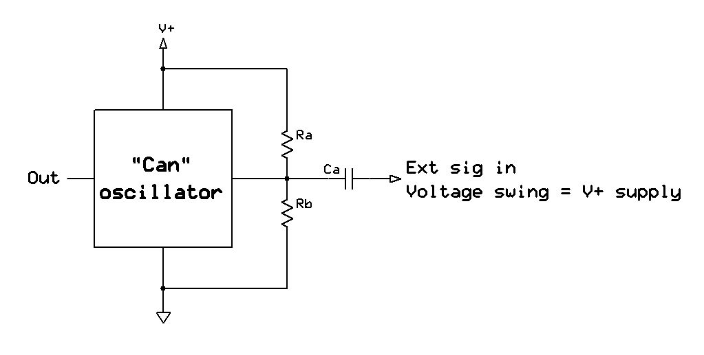
Many of these "can" oscillators have (or may be ordered with) an "enable" pin which turns them on and off - and unlike the power supply pin, this typically has pretty low parasitic capacitance compared to the V+ pin of the oscillator and it can provide a way "in" for the external frequency reference.  Figure 5 shows how this can be done.

For this circuit, resistors Ra and Rb (which may be between 1k and 10k, each) bias the "enable" pin somewhere around the threshold voltage and capacitively couple the signal - in this case, a +13dBm signal from a signal generator which had about 2 volt peak-to-peak swing.  If a logic-level signal is available, one can dispense with the bias resistors and the capacitor and drive it directly.

Note that some oscillators have a built in pull-up or pull-down resistor which can affect biasing and the selection of resistors should reflect that:  If its specs note that the pin may be left open to enable (or disable) the oscillator, this will certainly be the case.  If a pull-up resistor is present, the value of the corresponding external pull-down resistor will have to be experimentally determined, or "Rb" (in Figure 5) may be made variable using a 10k-100k trimmer potentiometer.

The 19.44 MHz oscillator shown in Figure 1 has such an enable pin and by injecting the 2 volt peak-peak signal from the external source into, it will reliably lock over a 900 Hz range.  Some degree of locking was noted even if the signal was quite low (around 250 mV peak-peak) but the frequency swing was dramatically reduced.  For optimal lock range it's expected that a swing equal to that of the supply rail would be used.

The precise mechanism by which this works is unknown:  Does the "enable" pin actually turn the oscillator on and off, does it simply gate the output of the oscillator while it continues to run or is it that this signal gets into the onboard circuitry and couples into the oscillator's feedback loop?  I suspect that it is, in most cases, the former as the "enable" pin often reduces power consumption significantly by completely turning off the oscillator section which would explain why it seems to work reasonably well - at least with the oscillators that were tested.

If the oscillator itself is "gated" (e.g. turned on/off) by the "enable" pin, then this is precisely the mechanism that we would want to inject an external signal into the oscillator.  In looking at the output waveform, however, I suspect that the answer to this question isn't that simple:  If it were simple logic gating one would expect to see the output waveform of the oscillator gated - and mixing - with the external signal once the latter was outside the "lock" range - but this was not the case for the oscillator tested.  I suspect that there might be some sort of filtering or debouncing in the gating circuit, but based on the ease by which locking was accomplished using this oscillator, there was clearly enough of the external signal getting into the oscillator portion itself to cause it to lock readily.

As noted previously, while the lock range was about 900 Hz, the oscillator itself was about 2.5 kHz high, anyway, so it could not be brought precisely onto the nominal frequency.  Again, it may be possible to do this with a TCXO equipped with an "enable" pin, but testing would be required for any specific oscillator to determine if this is viable.

"Locked" performance

The testing of spectral purity using either of these methods was only cursorily checked by tuning to the output of the oscillator with a general-coverage receiver and feeding the resulting audio into the Spectran program to see a waterfall display.  This configuration allows both the absolute frequency and the lock range to be measured with reasonable accuracy.

It can also tell us a little bit about spectral purity:  If there was a terrible degradation in phase noise, it would likely show up on the waterfall display - but when solidly locked, no such degradation was visible.

Although it wasn't tested, it's also likely that locking the oscillator - particularly using the "enable" pin - could be used to "clean up" an external oscillator that is somewhat spectrally "dirty" owing to the rather limited lock range and high "Q" of the "can" oscillator.  This is most likely useful for higher-frequency components (e.g. those farther away from the carrier than a few kHz) rather than close-in, low-frequency phase noise - a property which the most inexpensive oscillators likely don't have is anything resembling stellar performance, anyway.

Harmonic locking?

One thing that I did not try (because I forgot to do so) was harmonic locking - that is, the injection of a signal that is an integer fraction of the oscillator frequency (e.g. 1 MHz for the 4 MHz oscillator) - perhaps something to try later?

Is this useful for anything?

I had wondered for some time if it would be possible to lock one of these cheap oscillators to an external source and the answer appears to be "yes".  Unfortunately, most crystal oscillators have accuracy and temperature stability specifications that cause its natural frequency variance to exceed the likely lock range unless one gets a particularly stable and accurate oscillator.

If one presumes that the oscillator to be "tamed" is good enough then yes, it may be practical to lock it to an external source - particularly via the "enable" pin.  In many cases, such oscillators don't have this feature as they need to be active all of the time so it may be necessary to replace it with one that has an "enable" pin - and then one must hope that the replacement will, in fact, be stable/accurate enough and also capable of being locked externally - something that must be tested on the candidate device.

So the answer is a definite "Yes, maybe!"


This page stolen from ka7oei.blogspot.com

[END]