As technology moves on, it is getting more difficult to find custom-made quartz crystals.
Why would one need a quartz crystal in these days of frequency synthesizers? They can't really be beat for simplicity and stability in many applications. While it may be preferable in many cases to just use a cast-off synthesized radio, there are still some compelling reasons to use older "rock bound" radios used for linking and repeater where frequency agility is not important.
Many of these older radios have multi-section, narrow-band helical resonator front ends which provide protection above and beyond many modern radios and repeaters for rejection of off-frequency signals - often very important for linking and repeater sites: Many users have replaced their old "rock-bound" repeaters with "store bought" Icom or Yaesu repeaters at busy sites only to discover that these new radios - with their intrinsically broad front ends - were being clobbered by signals that managed to get around their duplexers!
For an explanation as to why that happens, read THIS article about duplexers: When "Band-Pass/Band-Reject duplexers really aren't band-pass"
Given that one might be using a rock-bound radio for a specific application, the recent demise of International Crystal Manufacturing (ICM) in the U.S. makes these crystals harder to obtain although there continue to exist other companies, such as "Quartslab" in the U.K., that can supply custom crystals.
What about retrofitting such a radio with a synthesizer?
The "ProgRock"
The "ProgRock" (short for Programmable "Rock" or crystal) is a device sold by QRP Labs in the U.K. (link) consisting of two parts:
- An Si5351A-based frequency synthesizer
- An Atmel-based microcontroller board that sets the frequency of the synthesizer.
The Si5351 chip, made by Silicon Labs, contains several on-board oscillators and dividers making it capable of producing frequencies ranging from high audio to somewhere "north" of 200 MHz with "parts per billion" resolution over most of that range. Capable of up to three independent frequency outputs, only two outputs are typically used owing to hardware limitation related to the number of internal synthesizer blocks and the fact that there is a bit of crosstalk between each of the three channels.
What this means is that while in theory one could use a single ProgRock for both receive and transmit simultaneously - as in a repeater - it may not be a good idea as low-level spurious signals from the "other" channel may cause low-level spurious responses: While this may not be an issue for receive, it would be a bad thing for a transmitter - particularly when used for full-duplex repeater service where extremely low-level spurious signals may get into the receiver or when the transmitter is at a shared site and very low spurious products could get into other people's receivers!
On the other hand, if the radio in question is half-duplex (e.g. not receiving and transmitting at the same time) one of the features of ProgRock, the ability to select multiple channel "banks", can be used to enable one channel with the receive frequency and then the other channel for the transmit frequency as needed. By having just one synthesizer active, the production of low-level spurious signal is minimized.
Note about the original ProgRock and newer ProgRock2:
Since this page was originally posted, QRP-Labs has discontinued the original "ProgRock" and replaced it with the "ProgRock2".
This new device has all of the features of the original ProgRock - plus it comes with a 0.25ppm TCXO, providing better stability than (pretty much) any crystal oscillator used in "rockbound" radios - and it costs the same, too! Additionally, it is much smaller, programmable via USB (using a serial port emulator) and it comes pre-assembled.
Important: If you use the ProgRock2, avoid powering it from more than 7-8 volts as the thermal design related to the onboard 3.3 volt regulator - which cannot tolerate more than 12.0 volts - is somewhat marginal at higher voltages - particularly at elevated temperatures. It is strongly recommended that it be powered from 5 volts (e.g. via a 7805 regulator).
Alternatively, knowing that the nominal current consumption of the ProgRock will be between 30 and 60mA - assuming worst-case, a 120-150 ohms 1/2 watt resistor will result in a voltage drop sufficient for 12-15 volt operation. The resistance is not critical - it just needs to result in 4-8 volts at the ProgRock2 under its expected load and frequency configuration.
For more information visit the QRP-Labs ProgRock2 web page - LINK.
While the original ProgRock is described as being used, it applies to the newer ProgRock2 as well.
Case study: The GE Mastr II
The GE Mastr II is a crystal-controlled product line made from the mid-late 1970s into the early 1980s and aside from a few minor issues (e.g. the tendency for the receiver 's helical resonator castings to grow "hair" [e.g. metal dendrites] and make the receiver deaf - a problem easily remedied by the application of spray-on clear coat after cleaning and degreasing) it is a solid performer with very strong receive filtering and the ability to get many of the parts on the new and surplus market. What we need, then, is to effectively simulate a crystal oscillator module (called by GE an "ICOM" - no relation to any other radio company!) to produce the desired frequency.
One potential advantage in this application is that the transmitter itself is modulated using phase modulation. What this means is that the crystal itself (or any other type of frequency source) is unmodulated, with the audio added in the later stages using variable reactance techniques and this means that we do not need to figure out how to modulate our synthesizer directly.
Having an unmodulated signal source as our transmit frequency determining component is actually quite convenient as it provides the opportunity to "nail down" the transmit frequency with as much precision as you wish, allowing multiple transmitters to be "synchronized" to precisely the same frequency. In contrast, transmitters with modulated crystals or PLLs have a tendency to "wander" a bit during modulation by amounts that may not be precisely matched between units and this can cause a bit of extra "clashing" of phase and frequency in overlap areas.
On the GE Mastr II receiver the crystal frequency is multiplied by a factor of 9 for high-band VHF (e.g. 2 meters) and 36 for UHF (70cm) typically using an IF (Intermediate Frequency) of 11.2 MHz in each case. For transmit, the crystal frequency is multiplied by 12 for high-band VHF and 36 for UHF.
What this means is that for a hypothetical repeater on 146.940 MHz with a -600 kHz split, the receive local oscillator would be operating at (146.340 - 11.2) = 135.140 MHz with a crystal frequency at 1/9th of this, or 15.015555MHz. The transmitter would use a crystal frequency of (146.940 / 12) = 12.2450 MHz.
For a repeater operating on 449.000 MHz with a -5 MHz split, the receive local oscillator would operate at (444.000 - 11.2) = 432.80 MHz with a crystal at 1/27th of this, or 16.029629 MHz while the transmitter would use a crystal frequency of (449.000 / 36) = 12.472222 MHz.
We can tell from the above numbers that for a receive frequency in either the U.S. 2 meter or 70cm amateur bands we would need to produce a signal in the general area of 15-16 MHz for receive and around 12 MHz for transmit with the GE MastrII radios.
Synthesizing the receive local oscillator's crystal:
Let us first analyze the case of the receive local oscillator for our hypothetical 449.000- repeater - that is, a 70cm repeater with a 449.000 MHz transmit frequency and a 444.000 MHz receive frequency.
 |
| Figure2: Signal path of the receive crystal showing the multiplier stages (highlighted). Note that the output of the crystal is sent almost immediately to a frequency tripler stage which allows us to inject a frequency at 3x the original crystal frequency at that point. Click on the image for a larger version. |
If one examines the signal path (see the block diagram to the right) from the output of the crystal oscillator unit you can see that one of the first stages after the crystal unit (the "ICOM") is a frequency tripler meaning that we don't need to start at 1/27th of the local oscillator frequency, but at 1/9th - three times that frequency, or 48.088888 MHz in the example above, effectively eliminating the need for the lower frequency that would get multiplied, anyway. In so-doing we get a bit better frequency resolution and potentially lower spurious signal generation and better phase noise response - more on that later.
Synthesizing the transmit crystal:
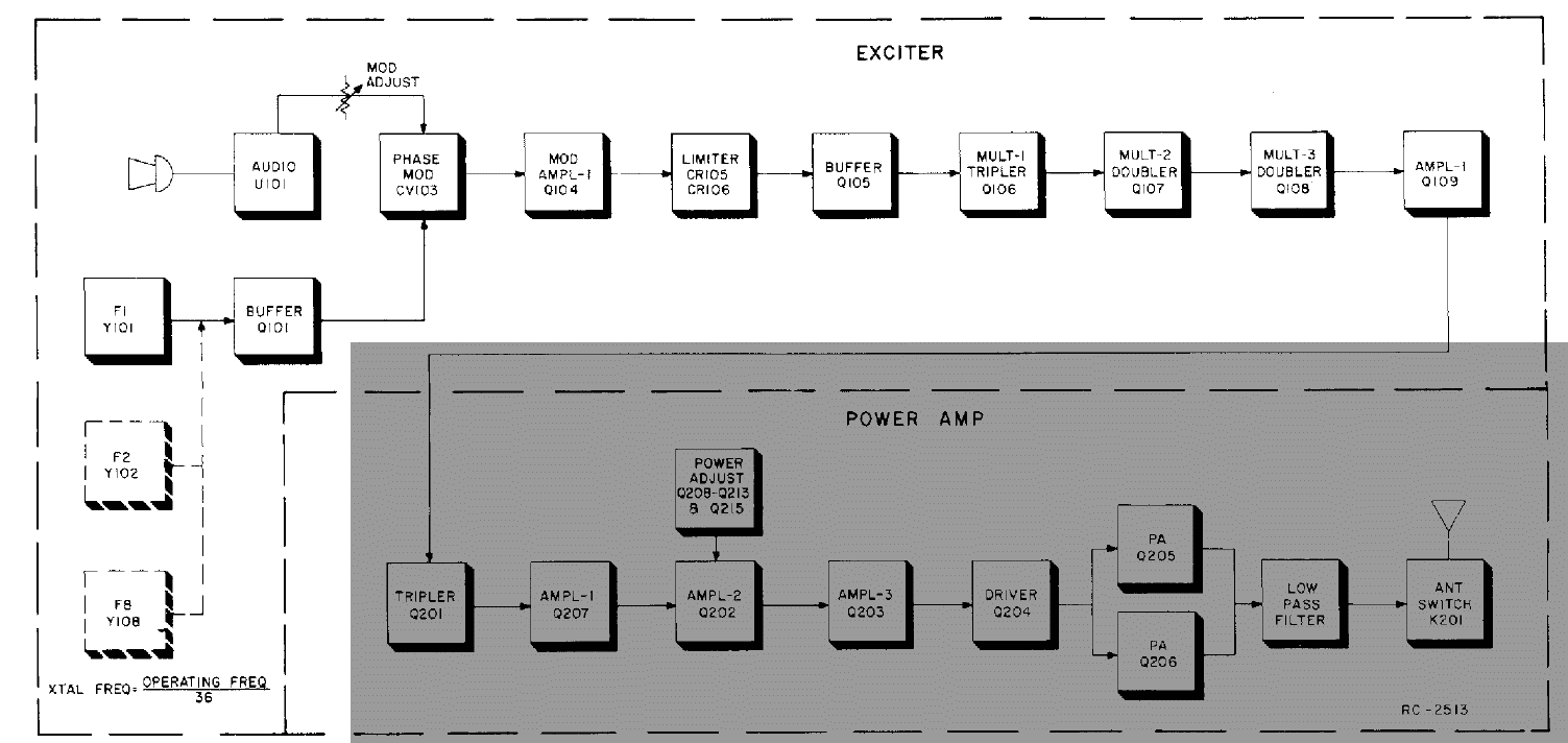 |
| Figure3: The signal path of the transmit crystal showing the modulation and multiplier stages, highlighted. The first stage beyond the crystal is the modulator meaning that we must synthesize a frequency that is the same as the original crystal. Click on the image for a larger version. |
Instead of going directly to a frequency multiplier as in the case of the receiver, the first stage beyond the oscillator unit is the phase modulator. For various reasons, when phase-modulating a transmitter it is best to start at the lowest frequency practical so that the small amount of linear modulation that is possible at a given frequency is multiplied along with the signal. What this means is that we are stuck at the 12.472222 MHz frequency that we calculated, above.
Modifying a GE "ICOM":
As mentioned above, the GE MastrII uses modules called ICOMs as the frequency-determining components with these modules containing the crystal, an oscillator circuit, a tuning capacitor and some additional electronic frequency-tuning circuitry - namely a varactor diode, and some additional circuitry to provide channel selection and transmit keying. There are three types of ICOMs commonly found in VHF and UHF radios:
- "2C" ICOM. This is nominally rated for 2ppm frequency stability and is typically used at UHF.
- "5C" ICOM. This is nominally rated for 5ppm frequency stability and is usually used at VHF. It can provide an external temperature-based frequency control voltage that is "shared" with "EC" type ICOMs.
- "EC" ICOM. This "Externally Compensated" ICOM uses the voltage provided by a 5C ICOM elsewhere in the radio for frequency stability. Normally, one would never use an "EC" ICOM all by itself as it has no temperature compensation of its own and without a 5C driving it, its frequency tuning voltage may be indeterminate.
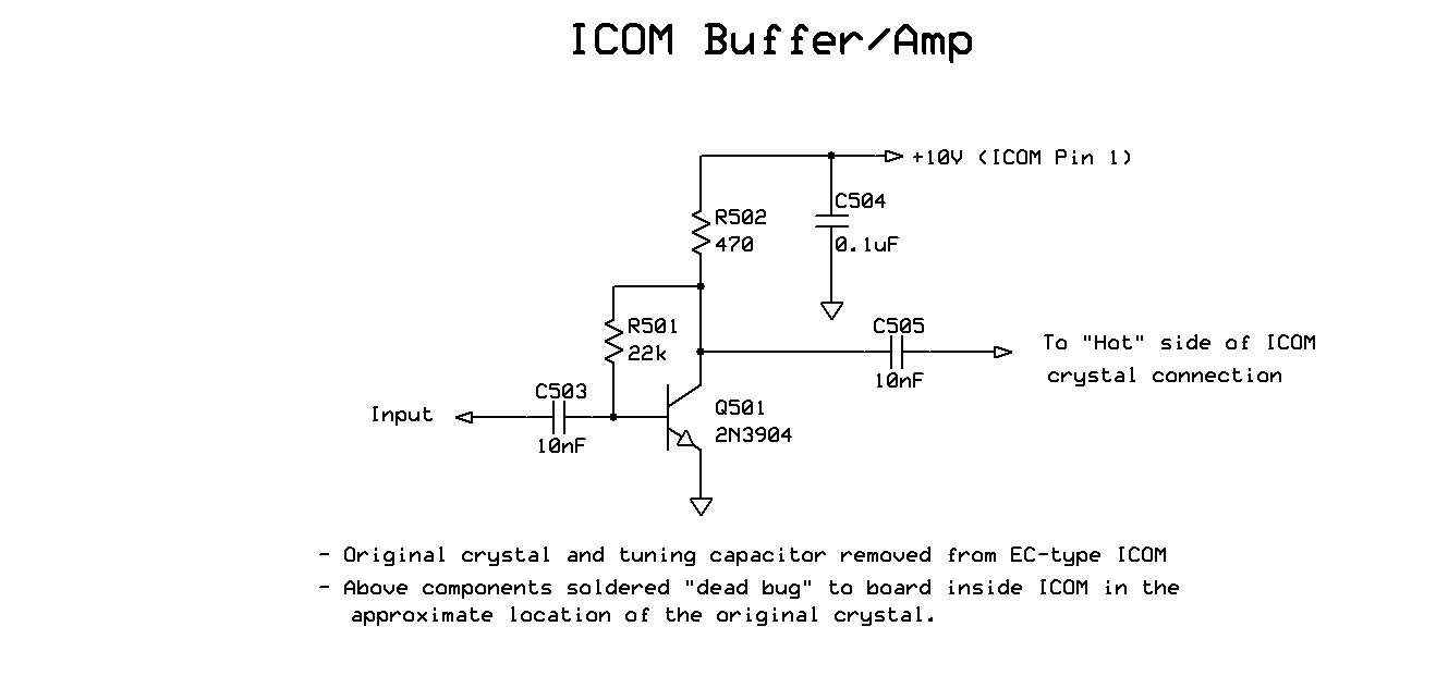 |
| Figure 4: A buffer/driver circuit added to an EC ICOM. This circuit is constructed within the ICOM unit itself. Click on the image for a larger version. |
 |
| Figure 5: The insides of the modified "EC" ICOM with the added circuitry built "dead bug" inside the original ICOM enclosure. The metal can is removed for this picture with the coaxial cable entering through the hole that originally accessed the tuning capacitor. Click on the image for a larger version. |
This circuit, a simple common-emitter amplifier, assures that signal from the synthesizer is at a consistent level - and one that is capable of fully-driving the original oscillator circuit to full output. While we can build a complete, new circuit for the ICOM, retaining its original oscillator circuit is a convenient means of keying the transmitter using the original PTT circuit in the MastrII radio.
While a bit cramped, there is enough room to build the simple circuit shown in the diagram above inside the original can. When this is done, the input of the circuit and its connection to coaxial cable is arranged such that it passes through the hole originally used to access the tuning capacitor. This circuit is insulated from the can using the "fish paper" that originally insulated the circuity and crystal from the can.
Putting it into practice:
To see if the synthesizer produced a transmit signal of acceptable quality, I decided to use a ProgRock in a 70cm transmitter. Because of the higher multiplication factor of the UHF transmitter, this would be a good "worst case" test to determine if the spurious content of the transmitted signal was cause for concern, as well as analyze the same signal in terms of phase noise to see if the synthesis process caused additional degradation of spectral purity.
Because it was on-hand, I tested using a UHF GE Mastr II transceiver, using unshielded clip leads to connect directly to the "ICOM" socket, including a 1000pF blocking capacitor to protect the ProgRock's Si5351a chip. The results were encouraging: A very subtle increase in the background noise (hiss) on both receive and transmit (the TX and RX testing was done separately) but no other obvious issues.
 |
| Figure 6: The as-built filter, using three 42IF129 10.7 MHz IF "cans". Click on the image for a larger version. |
In looking at the spectral purity of the transmitted signal, a slight amount of added noise was seen on a spectrum analyzer - well into the -90dBc range - within a few 10s of kHz of the carrier. Farther out, in doing an "A/B" comparison with a crystal on the same frequency we saw a few low-level spurious signals, but doing some "hand waving" (literally putting one's hand near the temporary clip-leaded wires) indicated that most of this was being picked up on the flying leads. A visible spur was seen at +/-1.32 MHz, but this was immediately recognized as being from an AM radio station located about 1.5 miles (about 2.4km) away and had a "proper" installation been done with shielded cables, it's likely that this would not occur at all.
Making it better:
Without making things complicated, there is little that can be done about the low level hiss, largely attributed to phase noise of the synthesizer - but it's unlikely that this would even be noticeable in a typical installation, and if VHF were used instead, it may not be audible at all. What would be prudent would be the use of a narrowband L/C bandpass filter on the output of the synthesizer to further-filter its output and knock down farther-removed signals (and their mixing products) that might find their way into the transmitter - particularly those related to the 27 MHz reference oscillator.
 |
| Figure 7: Schematic of the filter using 10.7 MHz IF transformers. Click on the image for a larger version. |
In the "old days" one option of filtering the oscillator output was with the use of tunable 10.7 MHz IF transformers, such as the "42IF129" that had been available from Mouser Electronics and other places as these could be tuned from below 7 MHz (with an added capacitor) to around 13 MHz with no modification - and even higher by removing the internal capacitor and using a smaller value external cap. Unfortunately, obtaining any 10.7 MHz IF transformers these days is difficult - although several surplus and hobbyist parts suppliers still have a few on hand.
The lack of ready availability of this particular type of component means that we would need to make a similar unit ourselves - described below:
 |
| Figure 8: An alternate version of the bandpass filter using more commonly-available components. Click on the image for a larger version. |
This filter is depicted in Figure 6, using readily-available components. The frequency range can be tweaked as needed: Changing the 82pF capacitors to around 100pF will allow tuning down to about 10 MHz while lowering them to 47pF will allow tuning around 14 MHz (20 meters). This filter's insertion loss (about 6 dB) is comparable to that depicted in Figure 7, with 15-20dB of attenuation at +/- 1 MHz and at least 40dB attenuation +/- 3 MHz.
Note: It is NOT the fact that the ProgRock puts out a
square wave with harmonics that is a concern - the output frequency of
the ProgRock is immediately multiplied to one of those harmonics. Again, it's the non-harmonic low-level spurious signals that are of concern.
Implementation:
The ProgRock has three outputs available, but depending on your application you may need to deploy two of them, as noted above:
- For half-duplex use, a single Prog-Rock could be used, one output for TX and the other for RX. In this case one would use the available "channel banks" and program it such that for TX, only that specific output would be enabled. For RX, one would use one of the channel bank bits to select a configuration in which the output of the TX is disabled and the output for the RX is enabled.
- For full-duplex use, the use of TWO separate ProgRocks is recommended: Even though it is able to output both frequencies simultaneously, the outputs of the synthesizer are susceptible to producing low-level spurious signals as these two outputs interact on the chip itself - and for this reason the isolation of two, individual units is suggested. On a GE Mastr II repeater, the TX and RX sections are isolated anyway, so spending the extra money to buy a second ProgRock to keep it this way is strongly recommended!
Mentioned above are the "channel banks": There are three bits available for selecting up to 8 separate configurations. If, on a half-duplex radio, one of these bits is used for selecting the TX and RX frequencies, two other bits remain available allowing up to 4 different frequencies to be selected. Similarly, in cases where two separate ProgrRocks are used (one for TX, the other for RX) up to 8 separate frequency configurations is possible.
Finally, the original ProgRock boards shipped with an imprecise "computer" crystal that is not temperature stable. The newer versions of the original ProgRock had the additional footprint for a TCXO (Temperature Controlled Crystal Oscillator) that will hold the frequency to within 2.5ppm - more than adequate for 2 meter usage: An article describing how to retrofit the unit with a 1ppm TCXO - suitable for UHF use - may be found here.
Update
The current-production "Progrock 2" - which sports a USB interface for programming - ships with a 0.25ppm TCXO so a retrofit for stability is unlikely to be required.
A word of warning: Although it is rated for up to 12 volts, I would recommend that you do NOT operate the Progrock 2 at higher than 8 volts!
* * * * *