 |
| Figure 1: Close-in responses of various filter combinations Yellow: Duplexer-only Magenta: Bandpass-only Cyan: Duplexer + Bandpass Click on the image for a larger version. |
There is a follow-up article to this one - "A simple VHF notch cavity from scraps of (large) heliax" - link.
The case for bandpass filtering
If you operate a repeater - or even a simplex radio such as a Packet node - that is located at a "busy" radio site, you'll no doubt be aware of the need for cavity-based filtering.
In the case of a repeater, the need is obvious: Filtering must be sufficiently "strong" to keep the transmit signal out of the receiver, and also to remove any low-level noise produced by the transmitter that might land on the receive frequency.
In the case of a packet or simplex node of some sort, a simple "pass" cavity is often required at a busy site to not only prevent its receiver from being overloaded by off-frequency signals, but also be a "good neighbor" and prevent low-level signals from your transmitter from getting into other users' receivers - not to mention the preventing of those "other" signal from getting back into your transmitter to generate spurious signals in its own right.
Comments:
- In this discussion, a "band pass" filter refers to the passing of ONLY a narrow range of frequency near those of interest and at odd multiples of the lowest resonant frequency - but nothing else. This does not refer to the "pseudo-band-pass" response - often seen in repeater duplexers - described below.
- It is HIGHLY RECOMMENDED that anyone attempting to construct this type of filter get and learn to use a NanoVNA: Even the cheapest units (approximately $50US) - when properly set up - will be capable of the sorts of measurements depicted in this article.
A Band-Pass/Band-Reject (BpBr) duplexer may not be what you think!
A common misconception is that a typical repeater duplexer - even though it may have the words "band pass" written on its label or in its specifications - has a true "band pass" response.
The problem becomes more apparent when we look over a broader frequency range. Figure 2 shows the same hardware, but over a span of about 30 MHz to 1 GHz.
 |
| Figure 2: The same as in Figure 1 except over a wider frequency range showing the lack of off- frequency rejection of a "BpBr" duplexer (Yellow) that is significantly mitigated by the addition of a band-pass filter (Cyan) Click on the image for a larger version. |
Keeping an eye on the yellow trace, you'll note that over most of the frequency range there is very little attenuation. What this means is that the "BpBr" filter doesn't exhibit a true pass response once you get more than a few MHz away from the design frequency.
I've actually had arguments with long-time repeater owners that disagreed with this assertion, but hadn't actually "swept" a duplexer over a wide frequency range: These days, with the availability of inexpensive test equipment like the NanoVNA, there's no good excuse for not determining this for yourself!
For more about this, see the related article linked here.
Why is this a problem?
In the "old days" radios that you would use at a repeater site were typically cast-off mobile radios - and even if you had a repeater, it was typically based on a mobile design. These older radios - often from the 80s or earlier - typically used a bank of narrowband (often Helical) filter elements, each tuned to the frequency of interest: If several frequencies were used, the system planners often placed then near each other so that they could be covered by the receivers' narrow filters without undue attenuation and because of this, one could "get away with" a duplexer with filtering that didn't offer a "true" pass-band response.
Most modern radios used in amateur repeaters are "broadband" in nature meaning that they often have rather wide receiver front-end filters: It is not practical to have electronically-tuned filters that are anywhere near as narrow as the Helical filters of the past which means that they simply lack the filtering to reject strong, off-frequency signals.
The poor filtering of some "new" radios:
When a modern radio is dropped in place of an old radio at a "busy" site with lots of other transmitters, disappointment is sometimes the result: The "new" radio may seem less sensitive than the old one - or it might seem that sensitivity varies over time. In reality, the "new" radio may well be being overloaded by the off-frequency signals that the old radio's resonator-based front-end easily filtered. What's worse is that the precise nature of this overload condition may be masked by the use of subaudible tones or digital tone squelch - and if this is a digital radio system like D-Star, Fusion or DMR, there may be no obvious clues at all as to the problem at hand unless one has the ability to measure and monitor the analog "baseband" from the receiver itself.
To be sure, if the receiver in question can operate in carrier-squelch analog mode, the usual techniques to determine overload (Iso-Tee measurements, injection of a weak carrier and observing SNR, etc.) may be employed to determine if there is an issue - but this, too, may be misleading as problems may be intermittent, showing up only when a combination of transmitters key up.
A simple pass cavity:
While not a panacea, the use of a simple pass-only cavity can go a long way to diagnose - even solve - some chronic overload issues - particularly if these have arisen when old gear was replaced. Suitable pass cavities are readily available for purchase new from a number of suppliers and used from auction sites - they are also pretty easy to make from copper and aluminum tubing - if you have the tools. Because of the rather broad nature of a typical pass cavity, temperature stability is usually not much of an issue in that its peak could drift hundreds of kHz and only affect the desired signal by a fraction of a dB.
Another material that could be used to make reasonable-performance pass cavities is larger-diameter hardline or "Heliax" (tm). Ideally, something on the order of 1-5/8" or larger would be used owing to its relative stiffness and unloaded "Q" and either air or foam dielectric cable may be used, the main difference being that the "Q" of the foam cable will be slightly lower and the cavity itself will be somewhat shorter.
 |
| Figure 3: Cutting the (air core) cable to length Click on the image for a larger version. |
The "Heliax bandpass cavity" described here can be built with simple hand tools, and it uses a NanoVNA for tuning and final adjustment. While its performance will not be as good as a larger cavity, it will - in many cases - be enough to attenuate strong, out-of-band signals that can degrade receiver performance.
Using 1-5/8" "Heliax":
The "cavity" described uses 1-5/8" air-core "Heliax" - and it is necessary for the inner conductor to be hollow to accommodate the coupling capacitors. Most - but not all - cable of this size and larger has a hollow center conductor. Cables larger diameter than 1-5/8" should work fine - and are preferred - but smaller than this may not be practical - both for reasons of unloaded "Q" and also if the center conductor is solid or if its inside diameter cannot accommodate the coupling capacitors described later on.
Note: The KF6YB article linked below contains some length calculators for coaxial cable.
Preparing the "shorted" end:
For 2 meters, a piece of cable 18" long was cut. For the air dielectric, it's recommended that one cuts it gently with a hand saw rather than a power tool as the latter can "snag" and damage the center conductor.
 |
| Figure 4: The "shorted" end of the stub with the slits bent to the middle and soldered to the center conductor. Click on the image for a larger version. |
For the "cold" (e.g. shorted) end, carefully (using leather gloves) remove about 3/4" (19mm) of the outer jacket and then clean the exposed copper shield with a wire brush, abrasive pad and/or sand paper. With this done, use a pair of tin snips cut slots about 1/2" (12mm) deep and 1/4" (6mm) wide around the perimeter. Once this is done, use a pair of needle nose pliers and remove every other tab, resulting is a "castellated" series of slots. At this point, using a pair of diagonal pliers or a knife, cut away some of the inner plastic dielectric so that it is about 1/2" (12mm) away from the end of the center conductor.
Now, clean the center conductor so that it is nice and shiny and then bend the tabs that were cut inwards so that they touch the center conductor. Using a powerful soldering iron (I used a 150 watter) or soldering gun - and, perhaps a bit of flux - solder the shield tabs to the center conductor all of the way around. It's best to do this with the section of coax laying on its side so that hot solder/metal pieces do not end up inside the coax - particularly if air-core cable is used. If you used acid-core flux, carefully remove it before proceeding.
With one end of the cable shorted you can trim back any protruding center conductor and file any sharp edges - again taking care to avoid getting bits of metal inside the cable or embedded in the foam. At some point, you should cover the shorted end with RTV (silicone) and/or good-quality electrical tape to prevent contamination by dust or insects.
Preparing the "business" end:
 |
| Figure 5: The "coupling tubes" soldered in place which receive the wires for coupling in/out. Click on the image for a larger version. |
Making coupling capacitors:
We now need to make two capacitors to couple the energy from the "in" and "out" connectors to the center resonator and for this, I cut two 3" (75mm) long pieces of RG-6 foam TV coaxial cable and from each of these pieces, I removed and kept the center conductor and dielectric - removing any foil shield and then stripping about 1/2" (12mm) of foam from one end of each piece.
At this point, you'll need some small copper tubing: I used some 1/4" O.D. soft-drawn "refrigerator" tubing, cutting two 2" (50mm) lengths and carefully straightening them out. To cut this, I used a rotary pipe cutting tool which slightly swedged the ends - but this worked to advantage: As necessary, I opened up the end cut with the deburring blade of the rotary cutting tool just enough that it allowed the inner dielectric of the RG-6 to slide in and out with a bit of friction to hold it in place..
Comment:
The use of 1/4" (6mm) O.D. copper pipe and RG-6 center conductor/dielectric isn't terribly critical: A different-sized copper or brass pipe could be used as long as two parallel pieces will fit inside the center conductor of the Heliax - and that the chosen center conductor and dielectric of the coax you use to make the capacitor will fit somewhat snugly inside it.
The reason for the two copper tubes is to prevent the two capacitors made from the center of the RG-6 from coupling directly to each other as all energy must first resonate the center conductor. Using these tubes - soldered to the center conductor/resonator - prevents such direct coupling, and it offers good mechanical stability.
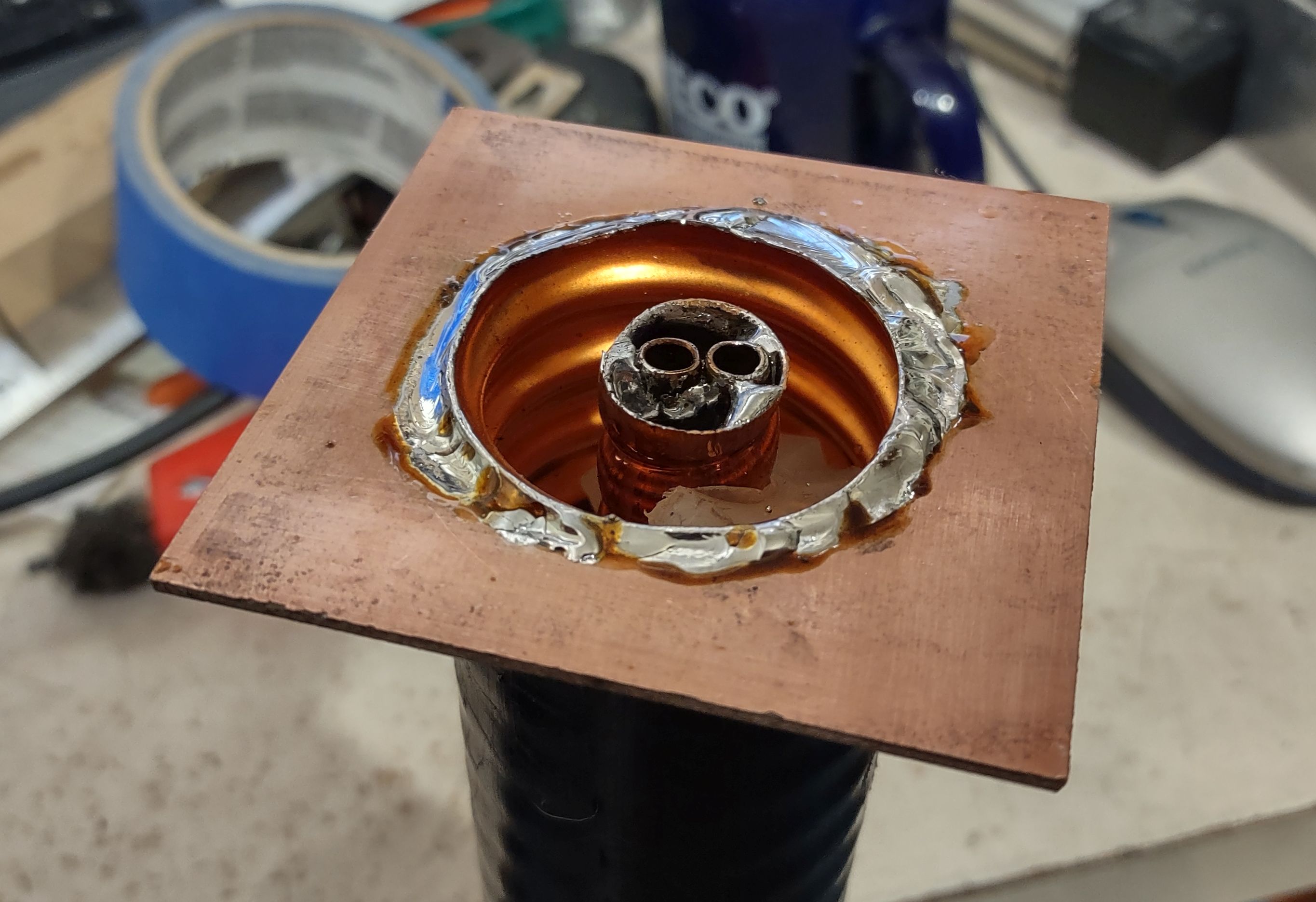 |
| Figure 6: The PC Board plate soldered to the end of the coax. Click on the image for a larger version. |
Using a hot soldering iron or gun, solder the two straightened pieces of tubing together, in parallel, making sure that the ends of the tubing that you adjust to snugly fit the outside diameter of the piece of RG-6 are at the same end. Once this is done, insert the two parallel pieces of tubing inside the Heliax's center conductor and solder them, the ends flush with the end of the center conductor, taking care not to heat them enough that they unsolder from each other: A pair of sharp needle-nose pliers to hold them in place is helpful in this task.
Making a box:
On the "business" (non-shorted) end of the piece of cable we need to make a simple box with a solid electrical connection to the outer shield to which we can mount the RF connectors with good mechanical stability. For the 1-5/8" cable, I cut a piece of 0.062" (1.58mm) thick double sided glass-epoxy circuit board material into a square that was 3" (75mm) square and using a ruler, drew lines on it from the opposite corners to form an "X" to find the center.
Using a drill press, I used a 1-3/4" (45mm) hole saw to cut a hole in the middle of this piece of circuit board material, using a sharp utility knife to de-burr the edges and to enlarge it slightly so that it would snugly fit over the outside of the cable shield: You will want to carefully pick the size of hole saw to fit the cable that you use - and it's best that it be slightly undersized and enlarged with a blade or file than oversized and loose.
 |
| Figure 7: Bottom side of the solder plate showing the connection to the coax. Click on the image for a larger version. |
After cleaning the outside of the coaxial cable and both sides of the circuit board material, solder it to the (non-shorted) end on both sides of the board, almost flush with just enough of the shield protruding through the top to solder it. For this, a bit of flux is recommended, using a high-power soldering iron or gun - and it's suggested that it first be "tacked" into place with small solder joints to make sure that it is positioned properly.
When positioning the box, rotate it such that the two "capacitor tubes" that were soldered into the center conductor are parallel with one of the sides of the square - this to allow symmetry to the connectors: This is depicted in Figure 8 where the left-hand and right-hand tubes (more or less) line up with their respective coaxial connectors.
Adding sides and connectors:
With the base of the box in place, cut four sides, each being 1-3/8" (40mm) wide and two of them being 3" (75mm) long and the other two being 2-1/2" (64mm) long. First, solder the two long pieces to the top, using the shorter pieces inside to space and center them - and then solder the shorter pieces, forming a five-sided (base plus four sides) box atop the piece of cable. As seen in the photo, the "short" sides are parallel to the two tubes in the center conductor.
As can be seen in Figure 8, there is a piece of PC board material about 1/4-3/8" (6-10mm) wide that goes between the two walls with the BNC connectors. This piece provides a bit of stiffening, minimizing flexure of the two walls with the connectors when cables are connected which could change the orientation of the two "RG-6 capacitors" - and it provides a small degree of shielding between the input and output wires that form these capacitors.
 |
| Figure 8: Inside the box with coupling/tuning stubs and lines and stiffening bar installed. Note the orientation of the tubes. Click on the image for a larger version. |
As can be seen in the picture, BNC connectors were used as they were convenient, but "N" type, SMA or even UHF connectors could be used - but the use of BNC connectors will be described.
The BNC connectors were mounted on opposite sides of the box, approximately 3/8" to the left of the center line and 3/4" from the bottom. As can be seen in the photo, the connectors were mounted in the "short" wall of the box such that our "RG-6" capacitors more or less line up with the capacitor tubes.
Now, insert the ends of the RG-6 center conductor into the "capacitor tubes" and, bending the top in an "L" shape, solder the end with the exposed center conductor to the coaxial connectors.
Also visible in Figure 8 - just to the right of the center conductor - are two pieces of copper strip, each about 3/4" (20mm) wide - one is soldered to the center conductor and the other to the ground inside the box. These two tabs form a very simple capacitor which may be used to "fine tune" the center frequency of the pass response by bending them nearer/closer to each other. While most of the adjustment of the center tuning will occur as one slides the two capacitors (made from RG-6) in and out, this method may also be used to provide a bit of additional tuning range.
Preliminary adjustment:
It is best to first set the RG-6 capacitors to obtain the desired pass response, taking into account the desired band-pass frequency, but once one has done this - and if the pass frequency is too high - one would then add the "copper tab" capacitors - perhaps more than one set. If the frequency is too low, see if you can obtain a suitable passband width (and acceptable insertion loss) by pulling these coupling capacitors out to raise the frequency: For most applications, an insertion loss of even 1 dB will not appreciably reduce receiver performance - particularly if the local noise at the site is rather high from other users and especially if the use of a band-pass filter like this is intended to minimize desense, anyway.
It is best to make them from metal (copper, brass) that is thick enough to not be springy on their own: Saving a piece and flattening the copper material from the shield of the 1-5/8" coax as you prepare it for use is suggested.
At this point we are ready to do some preliminary tuning - and this will require a NanoVNA or similar: It is presumed that the builder will have familiarity with the NanoVNA to make S11 VSWR and S12 insertion loss measurements on an instrument that has been properly calibrated at the frequency range in question.
Setting the NanoVNA to measure both VSWR and through-loss over a span of 130-160 MHz, connect it to the cable and you should see a pass response somewhere in the frequency range and if all goes well, the peak in the pass response will be somewhere in the 130-140 MHz range.
Adjusting the center frequency and passband response is an iterative process as reducing the coupling by pulling out the capacitors (the RG-6 center conductor) will also increase the frequency. Practically speaking, only about 3/8"-1/2" (9-12mm) of center conductor is needed at most to attain optimal coupling so don't be afraid to pull out more and more of the capacitors.
A bit of experimentation is suggested here to get the "feel" of the adjustment - and here are a few pointers:
Lowest SWR is obtained with the coupling capacitors are identically adjusted. If the SWR isn't below 1.5:1, try pulling out or pushing in one of the capacitors slightly to determine the effect - but move it only about 1/16" in each iteration. Generally speaking, pulling one out slightly is the same as pushing the other in slightly in terms of reducing VSWR.
Figure 9:
The band-pass filter sitting against a Sinclair
Q2220E 2-meter Duplexer - a good combination
for receiver protection at a busy repeater site!
Click on the image for a larger version.- The passband response will be narrower the less of the RG-6 center conductor is in the capacitor tubes - but the insertion loss will also go up.
- The frequency will go up the more the passband response is narrowed by reducing the coupling capacitors.
- With the lengths given (e.g. 17" for air-core 16-1/8" for foam core) the passband will be within the 2 meter band with the amount of coupling that will yield about 0.5-0.6 dB insertion loss. To a degree, you can "tune" the center frequency of the cavity by adjusting the coupling. It is recommended that you first tune for the bandpass response - and then tune it to frequency: See below for additional comments.
- It is recommended that you use a little coupling as needed to obtain the desired response. For example, if the cavity is "over coupled", the insertion loss will be about 0.5dB, but this will go up only very slightly as the coupling is reduced and the response is narrowed. At some point the insertion loss will start to go up as the passband is further-narrowed.
- As the coupling capacitor is pushed in, the resonant frequency will go down. If, even with the "tuning capacitor" (the copper strips)
are minimized in coupling, the frequency is too low, try pulling the
RG-6 capacitors out slightly to move it up in frequency: It's easy to
accidentally "over couple" the cavity by pushing them in too far and
causing it to tune low. It's likely that you can pull more of the RG-6
capacitors out and reducing coupling than you might first think and still
have acceptably-low insertion loss - and doing so will narrow the
passband response and improve ultimate off-frequency attenuation.

As mentioned above, it's recommended that the approximate passband width be set with the capacitors and if all goes well, the pass frequency can be adjusted with just the adjustment to the coupling with only a slight change in overall bandwidth. If, however, the desired "narrowness" results in a pass frequency above that which is desired, a simple "tab" capacitor can be constructed as shown in the photo.
 |
| Figure 10: The "close-in" response of the band-pass cavity. With the current settings providing a bit less than 0.5dB of attenuation at the center, it's rejection at the edges of the U.S. 2 meter band (144-148 MHz) is a bit over 8 dB. Click on the image for a larger version. |
With the preliminary tuning done, a bit of reinforcement of the box is suggested: A strip of copper circuit board material 3/8"-1/2" (9-12nn) wide is soldered between the inside walls of the box with the RF connectors. This strip minimizes the flexing of the walls with the RF connectors due to stresses on the connected cables which can change the orientation of the coupling capacitors and cause slight detuning.
With this reinforcement in place, do a final tweaking of the bandpass filter's tuning.
Final assembly:
As noted earlier, it's strongly suggested that the shorted end of the cavity be covered to prevent debris and insects from entering either the center conductor or, especially, the space between the shield and center conductor. This may be done using electrical tape or RTV (Silicone) adhesive.
 |
| Figure 11: A wider sweep showing the rejection at and below the FM broadcast band and up through 225 MHz. This filter, by itself, provides over 40 dB rejection at 108 MHz Click on the image for a larger version. |
Additional comments:
While the performance will vary depending on the coupling and tuning, the prototype, tuned for a pass response at 146.0 MHz, performed as follows:
- Insertion loss at resonance: <0.5dB
- -3dB points: -88 kHz and +92 kHz
- -10dB points: -2.5 MHz and +2.75 MHz
- -20dB points: -7.6 MHz and +11 MHz
- 2:1 VSWR bandwidth: 600 kHz
- Loss <=108 MHz: 40dB or greater
More detail about the response of this cavity filter may be seen in figures 10 and 11. In the upper-left corner of each figure may be found the measured loss and VSWR at each of the on-screen markers.
If a higher insertion loss can be tolerated, the measured bandwidths will be narrower. Depending on the situation, an extra dB or two of path loss may be a reasonable trade-off for improved off-frequency rejection - particularly on a noisy site where the extra loss won't result in a degradation of system sensitivity due to the elevated noise floor and the improved selectivity reduces off-frequency signals even more.
As with any cavity-type filter, there is a bit of fragility in terms of frequency stability with handling. If, after it is tuned this - or any cavity filter - is dropped or jarred strongly, the tuning should be re-checked and adjusted as necessary.
There's no reason why this cavity couldn't be used for transmitting, although using the materials described (e.g. the center conductors of RG-6) I would limit the power to 10-15 watts without additional testing.
As it is, this band-pass filter - in conjunction with a conventional 2-meter duplexer - can provide a significant reduction in off-frequency energy that could degrade receiver performance. As can be seen in Figure 2, the pass cavity may still pass energy from odd-order (3rd, 5th) harmonics that may fall within commercial/70cm and TV broadcast frequencies - but the addition of a VHF low-pass filter - perhaps even the VHF side of a VHF/UHF mobile diplexer - would eliminate these responses.
To be a good neighbor on a busy site it's strongly recommended that a pass cavity also be installed on the transmit side, along with a ferrite isolator (e.g. circulator with dummy load) to deal with signals that may enter into the transmitter's output stage and mix, causing intermodulation distortion and interference - both to your own receiver and those of others.
* * * * * *
Specific use cases:
Reduction of ingress from FM broadcast transmitters:
The most obvious use case would be the filtering of co-located FM broadcast transmitters. Despite being about 50 MHz off-frequency, a nearby FM transmitter - which often runs hundreds if not thousands of watts - can couple into a 2 meter antenna with sufficient energy to overload a receiver, causing the appearance of distorted audio from the wideband FM modulation of the broadcast transmitter to appear on the receiver. I have been on sites where the measured power at the receiver terminals, after passing through the 2 meter duplexer, have been on the order of 10 to 20 dBm (10-100 milliwatts) and actually registered as reflected power on an SWR bridge.
As can be seen from the above graphs and measurement, the filter described is capable of reducing this signal by at least 40 dB - likely enough to prevent gross overload of the receiver in question.
Reduction of commercial high-band VHF signals:
While less common these days, there are still systems like community repeaters operating above the 2 meter band in the 150-170 MHz range. These, too, can cause receiver degradation and the fact that these signals may be intermittent (e.g. a repeater that isn't used too often) can often frustrate the analysis of intermittent "desense" issues. Even this humble cavity is capable of reducing such a signal by about 20 dB at and above 155 MHz - more, if one were to reduce the coupling (and response bandwidth) of the cavity: In severe cases, the slightly higher insertion loss of the filter (say, 1.5 dB instead of less than 0.5 dB) may well be worth the trade-off in off-frequency rejection.
* * * * * *
"I have 'xxx' type of cable - will it work?"
The dimensions given in this article are approximate, but should be "close-ish" for most types of air and foam dielectric cable. While I have not constructed a band-pass filter with much smaller cable like 1/2" or 3/4", it should work - but one should expect somewhat lower performance (e.g. not-as-narrow band-pass with higher losses) - but it may still be useful.
Because of the wide availability of tools like the NanoVNA, constructing this sort of device is made much easier and allows one to characterize both its insertion loss and response as well as experimentally determining what is required to use whatever large-ish coaxial cable that you might have on-hand.
"Will this work on (some other band)?"
Yes, it should: Notch-only filters of this type were constructed for a 6 meter repeater - and depending on your motivation, one could also build such things for 10 meters or even the HF bands!
It is likely that, with due care, that one could use these same techniques on the 222 MHz and 70cm bands provided that one keeps in mind their practical limitations.
* * * * * *
Related articles:
There is a follow-up article to this one - "A simple VHF notch cavity from scraps of (large) heliax" - link.
- Second Generation Six-Meter Heliax Duplexer by KF6YB - link - This article describes a notch type duplexer rather than pass cavities, but the concerns and construction techniques are similar.
- When Band-Pass/Band-Reject (Bp/Br) Duplexers really aren't bandpass - link - This is a longer, more in-depth discussion about the issues with such devices and why pass cavities should be important components in any repeater system.
This article was stolen from ka7oei.blogspot.com
[END]


