 |
| Figure 1: The two generic "can" oscillators tested - both having been found in my "box of oscillators". Click on the image for a larger version. |
Sometimes one comes across a device with one of those cheap crystal "can" oscillators that is "close" to frequency - but not close enough. Perhaps this device is used in a receiver, or maybe it's used for clock generation or clock recovery. Such oscillator are available on a myriad of frequencies - although too-often not exactly the right one!
What if we want to "nail" this oscillator to an external (perhaps GPS) reference? If this oscillator were variable, this task would be simplified, but finding a "VCXO" (Variable-Control Crystal Oscillator) on the frequency of interest is sometimes not even possible.
What if there were a way to externally lock a bog-standard crystal oscillator to an external source?
To answer this question, I rummaged through my box of crystal oscillators (everyone has such a box, right?) and grabbed two of them: A standard 4 MHz oscillator and a 19.440 MHz oscillator that has an "enable" pin.
Comment:
This article refers to standard, quartz crystal oscillators and not MEMs or "Programmable" oscillators where the internal High-Q resonating element likely has no direct relationship with the synthesis-derived output frequency.
Injection locking
This is what it sounds like: Take a signal source of the desired frequency - typically very close to that of the oscillator that you are trying to nail to frequency - and inject it into the circuitry to lock the two together.
This technique is ancient: It accounts for the fact that a (wobbly) table of pendulum-type metronomes set "close" to the same tempo will eventually synchronize with each other, and it is the very technique used in the days of analog TV to synchronize their vertical and horizontal oscillators to the sync signals from the incoming signal.
It's still used these days, one notable example being the means by which an Icom IC-9700's internal oscillator may be externally locked to an external 49.152 MHz source (see: http://www.leobodnar.com/shop/index.php?main_page=product_info&products_id=352 ) - and this is done by putting a known-stable source of 49.152 MHz "very near" the unit's built-in oscillator.
Injection-locking a discrete-component crystal oscillator is relatively simple: It's sometimes just a matter of placing a wire near the circuitry (e.g. a "gimmick" capacitor) with the resonant element (e.g. near the crystal or related capacitors) and the light capacitive coupling will cause it to "lock" to the external source - as long as it's "close" to the oscillator's "natural" frequency.
Getting a signal inside the oscillator
Injection locking often needs only a small amount of external signal to be applied to the circuit in question - particularly if it's inserted in the feedback loop of the resonant circuit, but what about a "crystal can" oscillator that is hermetically sealed inside a metal case?
 |
| Figure 2: Schematic depiction of power supply rail to get the external signal "into" the can. Click on the image for a larger version. |
So what else can one do to get a sample of our external signal inside?
Power rail injection
The most obvious "input" is via the power supply rail. Fortunately - or unfortunately, depending on how you look at it - these oscillators often have built-in bypass capacitors on their power rails, putting a low-ish impedance on the power supply input - but this impedance isn't zero.
 |
| Figure 3: Top - The signal riding on the voltage rail Bottom - The locked output of the oscillator Click on the image for a larger version. |
When an external signal is applied to Q1 via C2 (I used +13dBm of RF from a signal generator) Q1 will conduct on the positive excursions of the input waveform, dragging the power supply voltage to the oscillator down with it. With this simple circuit, Q1 has to dissipate quite a bit of power (the current was about 500 mA) and this action results in a fair bit of power dissipation, likely due to the fact that the bypass capacitance within the oscillator is shunting the energy and causing a significant amount of power to be lost.
This circuit has room for improvements - namely, it's likely that one could better-match the collector impedance of Q1 with the (likely) much lower impedance at the V+ terminal of the oscillator - possibly using a simple matching circuit (L/C, transformer, etc.) to drive it more efficiently.
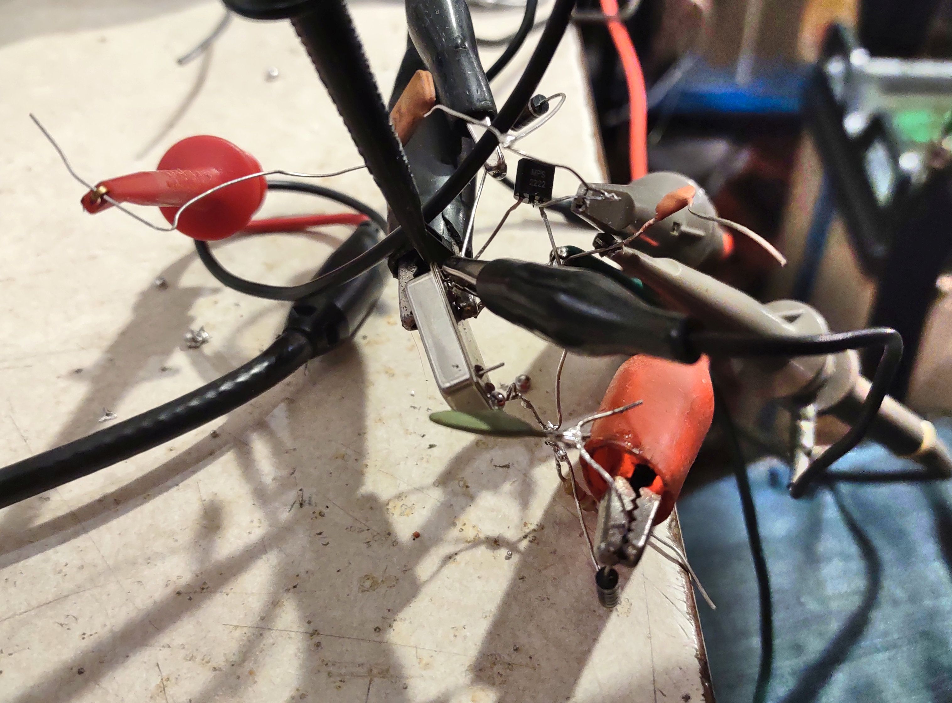 |
| Figure 4: The messy test circuit depicted in Figure 2 used to inject the external into the "can" oscillator via the power pin. Click on the image for a larger version. |
Despite its simplicity, with the circuit in Figure 2 shows how I was able to inject an external signal source into the oscillator and, over a relatively narrow frequency range (15 Hz for the 4 MHz oscillator, 60 Hz for the 19.44 MHz oscillator) it could be locked externally.
The oscillogram in Figure 3 shows the resulting waveforms. The top (red) is the AC-coupled power supply rail for the oscillator showing about 2 volts of RF imposed on it while the bottom rail shows the square-ish wave output of the power supply. Using a dual-trace scope, it was easy to spot when the input and output signals were on the same frequency - and locked - as they did not "slide" past each other.
As you might expect, the phase relationship between the two signals will vary a bit, depending whether one is at the low or high frequency end of the lock range and with changes in amplitude, so this - like about any injection-locking scheme - shouldn't be confused with a true "phase lock".
Is the lock range wide enough?
The "gotcha" here is that these are inexpensive oscillators, likely with 50-100 ppm stability/accuracy ratings meaning that they are going to drift like mad with temperature and applied power supply voltage. What this also means is that these oscillators are not likely to be "dead on" frequency, anyway.
To a degree, their frequency can be "tuned" by varying the power supply voltage: A 5-volt rated "can" oscillator will probably work reliably over a 3.5-5.5 volt range, often changing the frequency by a hundred Hz or so: The 19.44 MHz oscillator moved by more than 1.5 kHz across this range, but never getting closer than 2 kHz above its nominal frequency - but this correlates with the often-loose specifications of these devices in terms of frequency accuracy, not to mention temperature!
If your oscillator is "close enough" to the desired frequency at some voltage - and it is otherwise pretty stable, this may be a viable technique, but other than that, it may just be a curiosity. If one chooses an oscillator with better frequency stability/tolerance specifications - like a TCXO - this may be viable, but testing would be required to determine if a TCXO's temperature compensation would even work properly if the power supply voltage were varied/modulated with an external signal.
"Enable" pin injection
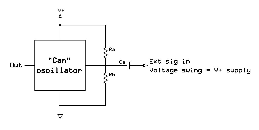 |
| Figure 5: Schematic depicting applying an external signal via the "enable" pin. The amplitude of the external signal must have a peak-to-peak voltage that is a significant percentage of the power supply voltage. Click on the image for a larger version. |
For this circuit, resistors Ra and Rb (which may be between 1k and 10k, each) bias the "enable" pin somewhere around the threshold voltage and capacitively couple the signal - in this case, a +13dBm signal from a signal generator which had about 2 volt peak-to-peak swing. If a logic-level signal is available, one can dispense with the bias resistors and the capacitor and drive it directly.
Note that some oscillators have a built in pull-up or pull-down resistor which can affect biasing and the selection of resistors should reflect that: If its specs note that the pin may be left open to enable (or disable) the oscillator, this will certainly be the case. If a pull-up resistor is present, the value of the corresponding external pull-down resistor will have to be experimentally determined, or "Rb" (in Figure 5) may be made variable using a 10k-100k trimmer potentiometer.
The 19.44 MHz oscillator shown in Figure 1 has such an enable pin and by injecting the 2 volt peak-peak signal from the external source into, it will reliably lock over a 900 Hz range. Some degree of locking was noted even if the signal was quite low (around 250 mV peak-peak) but the frequency swing was dramatically reduced. For optimal lock range it's expected that a swing equal to that of the supply rail would be used.
The precise mechanism by which this works is unknown: Does the "enable" pin actually turn the oscillator on and off, does it simply gate the output of the oscillator while it continues to run or is it that this signal gets into the onboard circuitry and couples into the oscillator's feedback loop? I suspect that it is, in most cases, the former as the "enable" pin often reduces power consumption significantly by completely turning off the oscillator section which would explain why it seems to work reasonably well - at least with the oscillators that were tested.
If the oscillator itself is "gated" (e.g. turned on/off) by the "enable" pin, then this is precisely the mechanism that we would want to inject an external signal into the oscillator. In looking at the output waveform, however, I suspect that the answer to this question isn't that simple: If it were simple logic gating one would expect to see the output waveform of the oscillator gated - and mixing - with the external signal once the latter was outside the "lock" range - but this was not the case for the oscillator tested. I suspect that there might be some sort of filtering or debouncing in the gating circuit, but based on the ease by which locking was accomplished using this oscillator, there was clearly enough of the external signal getting into the oscillator portion itself to cause it to lock readily.
As noted previously, while the lock range was about 900 Hz, the oscillator itself was about 2.5 kHz high, anyway, so it could not be brought precisely onto the nominal frequency. Again, it may be possible to do this with a TCXO equipped with an "enable" pin, but testing would be required for any specific oscillator to determine if this is viable.
"Locked" performance
The testing of spectral purity using either of these methods was only cursorily checked by tuning to the output of the oscillator with a general-coverage receiver and feeding the resulting audio into the Spectran program to see a waterfall display. This configuration allows both the absolute frequency and the lock range to be measured with reasonable accuracy.
It can also tell us a little bit about spectral purity: If there was a terrible degradation in phase noise, it would likely show up on the waterfall display - but when solidly locked, no such degradation was visible.
Although it wasn't tested, it's also likely that locking the oscillator - particularly using the "enable" pin - could be used to "clean up" an external oscillator that is somewhat spectrally "dirty" owing to the rather limited lock range and high "Q" of the "can" oscillator. This is most likely useful for higher-frequency components (e.g. those farther away from the carrier than a few kHz) rather than close-in, low-frequency phase noise - a property which the most inexpensive oscillators likely don't have is anything resembling stellar performance, anyway.
Harmonic locking?
One thing that I did not try (because I forgot to do so) was harmonic locking - that is, the injection of a signal that is an integer fraction of the oscillator frequency (e.g. 1 MHz for the 4 MHz oscillator) - perhaps something to try later?
Is this useful for anything?
I had wondered for some time if it would be possible to lock one of these cheap oscillators to an external source and the answer appears to be "yes". Unfortunately, most crystal oscillators have accuracy and temperature stability specifications that cause its natural frequency variance to exceed the likely lock range unless one gets a particularly stable and accurate oscillator.
If one presumes that the oscillator to be "tamed" is good enough then yes, it may be practical to lock it to an external source - particularly via the "enable" pin. In many cases, such oscillators don't have this feature as they need to be active all of the time so it may be necessary to replace it with one that has an "enable" pin - and then one must hope that the replacement will, in fact, be stable/accurate enough and also capable of being locked externally - something that must be tested on the candidate device.
So the answer is a definite "Yes, maybe!"
This page stolen from ka7oei.blogspot.com
[END]
No comments:
Post a Comment
PLEASE NOTE:
Be sure to be logged in to your Google account to post.
While I DO appreciate comments, those comments that are just vehicles to other web sites without substantial content in their own right WILL NOT be posted!
If you include a link in your comment that simply points to advertisements or a commercial web page, it WILL be rejected as SPAM!