Showing posts with label 6 meters. Show all posts

Thursday, January 28, 2021

Using surplus GE Mastr II and Exec II transmitters as amateur radio beacon transmitters

Back in 2000, a friend of mine (Glen, WA7X) wanted to place VHF and UHF propagation beacons at his cabin located in remote central Utah.  On-hand were used GE MASTR II Exec FM transceivers:  These radios - similar to the GE Mastr II - are crystal-controlled transceivers that date from the mid-late 70s and into the mid 80s and are still available surplus.  Available in "low", "high" and "UHF" band versions all amateur bands from 6 meters through 70cm may be covered (including 220 MHz with a bit of modification.)

For the purposes of beacon operation, it does not matter if the Mastr II or the Exec II (a slightly simpler, lower-cost version) is used as they share many of the same parts and some of the modules.  Of course, the receiver portion of the radio (front end casting, RF and IF boards) are not needed for beacon operation, but at least on the MVP, the interface board (on the "bottom" side) contains needed voltage regulators and the like.

To this end, three beacons - one each for 6 meters, 2 meters and 70cm - were constructed using modified (by me) GE MASTR II Exec radios and installed at a remote site belonging to WA7X.

Keying the transmitter:

The most obvious way to key the transmitter would be to use the PTT line - and this would work... sort of - but there are problems with doing it this way.

  • The PTT line keying the transmitter is fine for FM, but for keyed CW, the attack/decay waveform leaves much to be desired:  Severe "key clicks" are the result.
  • The crystal oscillator is actually keyed.  While you might get away with this on 6 meters, turning on and off the oscillator itself will likely result in an audible "chirp" - especially on 70cm!

What this means is that one needs to keep the oscillator running all of the time so that it remains stable and key farther down the signal path.  Fortunately, there is another way to key the radio.

Using the power control for keying:

These transmitters have a power control, of sorts.  In the PA (Power Amplifier) module there are a number of amplifier stages to take the 200-400 milliwatt signal from the exciter up to the rated output power of the final amplifier, typically 35 or 100 watts, depending on the type.  Typically the "pre-pre-driver" and "pre-driver" have their collector voltages fed via a series transistor and this voltage is made adjustable to set the amount of drive to the driver and output transistors.

While one could simply key this voltage, there is a problem:  Because all of the stages are "Class-C" type (e.g. non-linear) key clicks would surely result if the pre-pre-driver and pre-driver voltages were simply turned on and off.  What's more is that with this non-linear RF circuitry one will, as the drive power is increased by adjusting that voltage upwards, get no RF output at all - but very suddenly, the RF output will appear and increase very rapidly with respect to voltage - and then, suddenly, the rate of increase starts to drop again very quickly.  In other words, over a very small adjustment range one will go from no power at all to full power.  If we want both "clean" keying signals and to be able to select a given power level, things get a bit more complicated.

What this means is that you really can't use the original power control circuit for keying, either, but another, fairly simple circuit may be substituted, described below:

Figure 1:
Beacon power controller schematic.  This circuit not only provides keying shaping, but allows one to select three pre-set output power levels.  The PTT line of the transmitter itself is asserted all of the time causing the oscillator to run continuously.
Click on the image for a larger version

Explanation of the keying/power control circuit:

A sample of the RF voltage is provided (the terminal "From RF Power Detector") and applied to U1A, which is a unity-gain follower.  This voltage, from the RF detector, is then applied via U1D, wired as a unity-gain, inverting amplifier:  If the RF output of the amplifier - which is the voltage from U1A - drops below that of that applied to its inverting input, its output will go higher which, buffered by U1C, will turn on the output 2N3904 stage some more, causing the modified RF amplifier (described below) to produce more power.  The non-inverting input of U1D is provided from the "1 watt adj." potentiometer via U2A and in this way, the output power can be made variable by its setting.

The above circuit controls the amplifier power output via a closed-loop servo - but keying it while minimizing key "clicks" must still be done.  The keying input (active high - that is, ground = un-keyed, voltage = keyed)  is applied via U2B, wired as a comparator:  Its noninverting input is supplied from the output of U2A only because it was a convenient voltage somewhere between 2 and 4 volts.

When the transmitter is keyed, U2B's output goes low, but the minimum voltage is set to be three diode drops below the output of U2D and this discharges the 0.47 capacitor on the non-inverting input of U2C slowly through the 220k resistor.  Conversely, when unkeyed, the output of U2B goes high and that same 0.47uF capacitor is charged more quickly via the 22k resistor and its higher voltage is ilmited by the single diode "pointing" to the output of U2D.  The ultimate result of this is a voltage-limited keying waveform being applied to the non-inverting input of U2C that has carefully-controlled rise and fall times.

When the voltage applied to the noninverting input of U2C rises ("unkeyed") its output voltage also rises and is conducted into the same signal line as the "Power Detector" via a diode:  This high voltage - seemingly from the RF power detector - signals as if the RF power output is too high and the RF output is dutifully reduced to zero in response.  Conversely, when the transmitter is keyed, the output of U2C drops and its output diode no longer conducts, the RF output rising to that set by the power control.  The rise/fall of the signal being applied to U2C minimizes key clicks.

In reality, there is only one power level setting - the "1 watt adj" - and this is, by far, the most sensitive, requiring the greatest amount of control.  To effect higher power settings (e.g. 10 watts and 100 watts) the beacon controller turns "on" one of two N-channel FETs with series potentiometers in the drain lead:  When the respective FET is turned on, this parallel resistance shunts the output of the RF detector, requiring more RF power to be output to achieve the same voltage as before, increasing the RF output power as appropriate.  Of course, this means that when calibrating everything, the "1 watt" power setting must be done first!

Modification to the GE RF amplifier module:

Power control:

The GE MASTR power amplifiers' output power was originally controlled by a module that either did so by sensing the RF output from a power sensor, or "open loop" using a thermistor to try to compensate for the change in amplifier gain with temperature.  In either case an NPN emitter-follower transistor was placed in series with the supply voltage for the first two driver stages:  The higher the voltage on the base of this NPN transistor, the more voltage applied to these stages - and the higher the driver (and output) power.

Figure 2:
Modifications to the GE amplifier board
Click on the image for a larger version
This NPN transistor was replaced with a PNP or P-channel FET that allows the output power to be controlled by pulling the control pin (base or gate, as appropriate) low (e.g. toward ground):  It is this line that is pulled toward ground by the control circuit depicted in Figure 1.

The center-left insert of Figure 2 depicts this modification using a PNP Darlington transistor:  It simply replaces the original NPN follower - a task that requires a bit of rewiring and the addition of the two transistors shown.  (A standard non-Darlington PNP was originally tried, but it proved difficult to turn it "on" enough to provide 100 watts of RF output.)

A somewhat better option is the use of a P-channel power FET:  The same combinations of 1k resistors (gate-source, gate-control) are used:  The "loop gain" of the FET circuit is somewhat lower than that of a bipolar Darlington pair but being a FET, it is very easy to drive.

RF Sensing:

Figure 3:
The RF power sense circuit, coupled to the RF output
While some versions of the GE amplifier modules have built-in RF sensing, some (e.g. the MASTR Exec II) do no, so the circuit depicted in the upper-left corner of Figure 2 is required.  This is simply a small piece of wire laid atop the trace that goes from the output of the RF amplifier to its low-pass filter as depicted in Figure 3.  The desired amount of coupling is that which will yield approximately 2.5 volts of DC output across a 47k resistor at 1 watt of RF output.

Conversely, a small-value (e.g. 2-50pf) ceramic variable capacitor could be used to couple to the detector diode rather than the piece of wire:  It must have a 100 volt rating, minimum, and initial adjustment would start from the lowest-capacitance.

Temperature stability:

As expected, the power will vary slightly with temperature - but between summer and winter, only about 5% power variance has been noted.

Beacon keying:

The keying for this beacon is provided by a simple PIC-based controller that simply keys an output line with the Morse message, but any device that can store/send Morse could be used.  The only departure from a standard device - like a "WinKeyer" - is that it has outputs to select 1, 10 or 100 watts for different parts of the message.  The majority of the beacon message is transmitted at the 10 watt level to reduce overall power consumption, but it contains an embedded 5-second key-down (and accompanying message) at all three power levels.

The code for this keyer is very simple (if you wish to have a copy, send me an email) and could be easily implemented on about any similar device:  An Arduino mini would be a more contemporary choice.

As mentioned above, the transmitter's original PTT line is keyed all of the time that the beacon is in operation, causing the oscillator to be continuously running.  The only exception to this is that a remote (IP-controlled relay) device is connected to the PTT lines of these radios allowing the transmitters to be disabled remotely.

* * *

These beacons have been in operation at the WA7X site since late 2000 - over 20 years at the time of writing:  They have been extremely reliable - the only issues occurring fairly early-on and being due to random component failures, and their signals have been heard far and wide.

For more information about this beacon and its history, see the "WA7X Beacon Technical page".

This page stolen from ka7oei.blogspot.com

[End]


Sunday, June 9, 2019

Using the same feedline for HF/6 meters and 2 meters/70cm (with a diplexer)

Yesterday, a work party went to the remote HF station of the Utah Amateur radio club to install a new antenna for the lower HF bands.  At the site was an existing G5RV-type antenna which provided coverage on 80, 40, 20 and 10 meters (more or less) - but it didn't provide 160 meter coverage (mostly useful during winter months, after sunset) and this G5RV was not taking full advantage of the 65 foot tower on site, being anchored near the top, but sloping down toward ground that was also rising to the west.
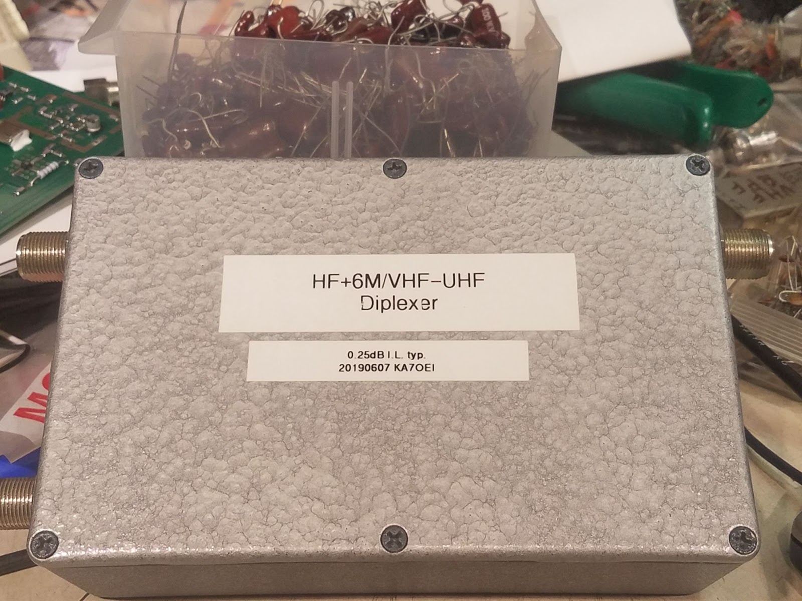
Figure 1:
The exterior of the completed diplexer designed to allow
HF+6 meters to co-habitate with 2 meters and 70cm on the same feedline.
Click on the image for a larger version.

Taking this antenna design on as a project, former Utahn/club member Mike, WA7ARK, decided to take advantage of his recent research, simulating, and real-world testing of multi-band end-fed half-wave antennas 1 and suggested a 160 meter end-fed half-wave wire:  If it worked as expected, it would provide useful coverage over the lower half of the 160 meter band, much (if not all) of 80/75 meters, 60 meters and 40 meters:  It may also be useful on 20 and 10 meters as well.

In short, the 1/2 half-wave antenna consists of approximately 260 feet of wire fed at roughly the 0.45 wavelength point by a 1:7 broadband transformer to provide a 49-fold impedance transformation.  When done properly, this combination can provide a reasonably good 50 ohm match on the first 3 or 4 half-wave multiples, (e.g. 160 meters=1/2 wave, 80 meters=2/2 wave, 60 meters=3/2 wave, 40 meters=4/2 wave, 20 meters=8/2 wave, 10 meters=16/2 wave.)  Much above 40 meters, the antenna was expected to lose effectiveness - at least in part due to the higher-order multiples, but also with the transformer "running out of steam" (getting lossier) at the higher frequencies.

But I digress...

No antenna is useful without some sort of feedline.  At the top of this tower was already-mounted a VHF/UHF fiberglass vertical fed with 1/2" Heliax (tm) hardline and rather than going through the trouble of running yet another feedline - which would be possible, but probably take more time than we'd have in just one day of our work party - I decided to construct a device that would allow this one feedline - which would be lower-loss than, say, RG-8 style coaxial cable - for both the HF and VHF/UHF antenna:  Because we'd be "force feeding" the antenna at impedances other than 50 ohms to attain greater operational bandwidth on the covered bands there was incentive to use the lowest-loss transmission line possible.


A "high/low" diplexer:

The solution to this problem is to employ a diplexer - a device that will take the signals from a common port and send high frequencies to the second port and low frequencies to the third port.  In this case, I started out with the basic design goals:
  • Use an inductor-input low-pass filter with a cut-off set comfortably above the 6 meter band - say at 65 MHz.
  • A capacitor-input high-pass filter with the cut-off set comfortably below the 2 meter band - perhaps 110-130 MHz.
Using the (free!) Elsie filter design program I plugged those values in and did some tweaking, ultimately deciding that an "N=5" Chebychev filter with 0.01dB ripple seemed to be appropriate.  I had to model these filters independently of each other because the free version of the program did not allow them to be bridged together at a common point - but taking the values given by the program and plugging them into "LTSpice" (by Linear Technologies - now Analog Devices) to simulate the combined circuit permitted a more analysis and "virtual" tweaking.

As expected, bridging the two filters at a common point "messes up" the response a bit - but for a circuit as simple as this, some experiment tweaking of values is all that is really needed.  Once I was satisfied with the result, I constructed one of these devices and analyzed it with my (relatively newly-acquired) DG8SAQ VNA to assess both the insertion loss and the matching.

The response for "6 meters and below" is as follows:

Figure 2:
The "low side" response of the diplexer with the VHF+ port terminated.  As can be seen, the insertion loss is below 0.5dB with a "reasonable" match at all frequencies 6 meters and below.  The isolation of this filter at 2 meters and above is well over 45dB.  The spurious response at the top end of this sweep (at around 725 MHz) is likely due to a resonance of the enclosure and has no bearing on its intended use.
Click on the image for a larger version.

At this point I should mention that the need for this filter arose rather suddenly:  About two weeks ago, we had taken inventory of what feedlines were available on the site and knew that we would be "short" a feedline - and in the likely event that we (probably) would not have the time to run a new one, I designed and constructed this diplexer - and a duplicate (one of these is required for each "end" of the cable!) - over the course of two evenings.  Had I more time I'm sure that I could have tweaked values a bit and reduced the insertion loss even more.

Moving the VNA to the VHF/UHF port and putting the load on the HF+6 meter port, I ran another sweep, which looked like this:

Figure 3:
The "high side" response of the diplexer with the HF+6 meter port terminated.  The insertion loss here is actually lower than that on the HF port - at least on the 2 and 70cm bands.    The isolation at 6 meters is a bit over 30 dB, increasing to over 60dB at 10 meters - more than adequate for our purposes.
Click on the image for a larger version.
As with the the "low" side, I'm sure that a bit of extra tweaking would have helped things a bit, but for its intended goal - providing an RF path to VHF/UHF vertical - its performance was plenty good - comparably to a commercially-available device.


Figure 4:
Inside the diplexer.  The diplexer was constructed in a box
that had previously been used for some satellite equipment.  The circuit
itself was built "dead bug" style on a piece of glass-epoxy circuit board.
The "common" HF-UHF in/out port is in the upper-left corner, the VHF-
UHF port in the upper right and the HF+6 meter port in the lower-left.
Note that the leads in the VHF/UHF path are kept as short as possible
with the components laying against the ground plane.
Click on the image for a larger version.
Figure 4 shows the interior of the constructed diplexer, built inside a Hammond 1590D die-cast aluminum case from a discarded piece of satellite equipment.  As it happens, the N-type connectors with attached lengths of UT-141 50 ohm hardline had been part of this same equipment and were put to use for the three input/output lines.  The use of the "N" type connectors were ultimately helpful as they are better-suited for outdoor use as they are designed to be weather-resistant on their own:  The connectors on the outdoor box were sealed with tape and wrap, anyway!

The capacitors used are NP0/C0G type ceramic disk, each rated for at least 1kV (and hi-pot tested to 3 kVAC - a bit over 4kV pk) and the inductors themselves are wound using tin-plated 12 AWG copper wire.  It is expected that this device should be able to handle at least several hundred watts on HF and 6 meters over a wide variety of mismatch conditions and 100 watts on 2 meters and 70cm.

Again, had I more time - and were it absolutely necessary to reduce the insertion loss even more - I would have done more tweaking of the capacitor and inductor values 2.  While the insertion loss on the VHF/UHF port is gratifyingly low, it would have no doubt been even lower if surface-mount capacitors and 50 ohm strip-line had been employed.  Finally, this device could have been constructed in an enclosure of about 1/3rd this size - particularly if a circuit board had been made along with a bit of clever arrangement of the components - but I used what I had, in the time that I had.  Because we needed two of these - one at each end of the feedline - I replicated the first and was happy to get identical results.

Diagram:

The schematic diagram of the as-built filter along with some component information is depicted in Figure 5, below:
Figure 5:
The schematic diagram of the as-built filter along with information about the parts used. The "half turn" specified is simply due to the fact that when you wind a coil so that both wire ends point in the same direction, an extra half-turn naturally exists.  The major modification required when the input of the high-pass section was bridged with the low pass section was to change the value of C3 from 33pF to 18pF.
The "nominal" predicted values of the inductors are:  L1=L3=93nH;  L2=192nH;  L4=L5=47nH. In construction, extraneous factors will require a bit of tweaking of these values to achieve best performance.
Click on the image for a larger version.
All of the inductors are wound using 12 AWG tin-plated solid copper wire on a 3/8" (9.5mm) O.D. drill bit as a former.  12 AWG wire is probably overkill, but tin-plated wire was readily available in this size:  As small as 16 AWG wire could have been used - particularly on the "High" (2M/70cm) side with little impact on insertion loss, but since HF energy actually flows through L1-L3, I would not recommend using wire smaller than that:  The use of smaller wire would somewhat increase inductance for the same number of turns so coils using it would have to be modified accordingly.

All of the capacitors are of the low-loss NP0 (a.k.a. C0G) type and no other type of ceramic capacitor should be used.  If desired, Mica capacitors may also be used:  These may offer slightly lower losses - particularly on VHF and UHF - but they are typically much more expensive.  If only low powers are expected (less than 25 watts) then 50 volt capacitors will suffice, but if a full 100 watts is anticipated on HF - particularly if a radio's built-in antenna tuner is used - that C1, C2 and also C3 (which "sees" the HF energy) be rated for at least 500 volts with 1kV being preferred.  For VHF/UHF power levels up through 50 watts or so, 100 volt capacitors are adequate for C4 and C5.

It should go without saying that the junction between J1, C3 and the end of L1 be kept as short and compact as possible, as poor construction practices here - and with the remaining components in the VHF/UHF path - will result in higher losses.  It is recommended that when constructing this circuit on a ground plane such as a piece of un-etched circuit board material (as seen in Figure 4) that all of the VHF/UHF branch components be laid flat, as close to the ground substrate as possible:  If one wishes to etch a circuit board, a 50 ohm strip line  along with surface-mount capacitors of appropriate voltage rating would be preferred and lots of "vias" (or holes+wires tying the back side of the board to the front) should be used.

* * * * * * * * * * * * * * *

In use:

A pair of these devices were installed yesterday at the remote radio site:  One located atop the tower near the feedpoints of the VHF/UHF and the HF antennas and the other indoors, where the feedline enters the building, where the cable from the HF/6M port goes to the HF-6M transceiver and the other goes to the 2 meter/70cm dual band transceiver.

At least with moderate VSWR levels (e.g. up to 4:1 or so) the components within this diplexer should have minimal effect on matching - at least on the lower HF bands.  Because the "new" antenna was designed mainly for operation from 160 through 40 meters, the diplexer should be more or less "invisible" over this VSWR range - which is also about as much range as radios' built-in tuners can typically handle, anyway.  Although no scientific testing was done, there was no discernible effect on the performance of the VHF/UHF radio system.

For the diplexer located atop the tower, three small drain holes were drilled in the side facing downwards and in addition to the connectors (all N-type, which are ostensibly weatherproof) being sealed with appropriate methods, a bead of silicone was run along the seam of the die-cast box that was facing upwards.  These precautions should prevent moisture from accumulating in the box and based on past experience, it should experience a long service life.

* * *

Footnotes:

1 - Mike's recent experimentation has been with end-fed half-wave antenna.  While the traditional end-fed antenna (e.g. a "Zepp") has been used for about a century, this differs from the traditional implementation by using a broadband matching transformer to match to the high impedance "near" the end of the 1/2 wave section so that, unlike a traditional Zepp, it will work on multiple bands' half-wave harmonic multiples - and the use of this transformer has the added advantage of providing a DC ground for the wire to eliminate static accumulation.

The strategic placement of this transformer, along with a short "tail" of cable connected to the transformer and appropriate feedline decoupling, multi-band operation without inducing currents along the feedline itself, yielding performance very similar to that of a 1/2 wave dipole at its fundamental frequency while allowing operation on more harmonic frequencies than is typically possible with a standard center-fed dipole.   With antenna lengths appropriate for 160 and 75 meter phone, the 40 meter "resonance" turns out to be just above the 40 meter band, but a small inductor was placed in a 40 meter current node near the far end of the antenna and this moved the resonance near the middle of the band without having an effect 160 or 75 meters.  The transformer that was used was supplied by "myantennas.com" and was designed for the 160-40 meter frequency range.

The use of an end-fed half wave can be advantageous over a dipole since, unlike a dipole, there are only two "ends" that may need to be supported which may be more convenient in instances where there is a single elevated structure for attachment while avoiding the weight and sag of a feedpoint (which may include a balun) that might be located mid-span.  Its relatively high feedpoint impedance can, if the antenna is properly installed, reduce the amount of current flowing in other structures (e.g. the tower itself, the feedline) as compared to an antenna like a "sloper" and both reduce the probability of RFI being caused by transmitted energy as well as interference conducted from the ham shack's electrical system, onto the feedline and antenna - provided that the proper precautions are taken.

2 -  A VNA (Vector Network Analyzer) is pretty much the ideal tool for characterizing a device like this, but satisfactory results could have been obtained using simpler devices.  Insertion loss could be measured using a pair of known-accurate watt/VSWR meters with one on the input and another on the output of the "leg" of the filter, terminating the meter on the output side with a known-good 50 ohm load.  Spot-checks would be done on frequencies - such as on the band nearest the edge (e.g. 6 meters and 2 meters for the low and high sides, respectively) as well as the "next" bands over (10 meters and 70cm.)  Iterative measurements of best VSWR and lowest measured losses should get one "pretty darn close" to optimum.

Similarly, one could use the meter on the input to monitor for changes in the VSWR, iteratively tweaking the inductors as necessary to minimize both VSWR and insertion loss.

* * *

This page stolen from ka7oei.blogspot.com

[End]
Tuesday, October 27, 2015

6 meter cycloid dipole for circular polarization

A 2-meter version of this type of antenna (the Cycloid Dipole) has been discussed here before - see the August 5, 2013 entry, "A Circularly-polarized 'Omnidirectional' antenna" - link.

Way back in 2000 or thereabouts I slaved over a hot keyboard and bruised my branium with the voluminous numerical output from the NEC2 program - a decidedly user-unfriendly antenna analysis and simulation tool - and derived the dimensions of a 6 meter "cycloid dipole".  I wasn't shooting for 6 meters, specifically, but the initial "stab" at dimensions seemed to indicate via simulation that, in this general frequency range, the structure that I'd inputted exhibited a vague semblance of the desired characteristics - namely, omnidirectional properties near the horizon and circular polarity with a reasonable axial ratio, so I ended up with an antenna at that frequency.
 
Figure 1: 
The "Ring-and-Stub" form of the Cycloid dipole.

This is a strange-looking antenna in either its original round ("ring-and-stub") form (Figure 1) or the easier-to-build "square" shape seen in Figure 2.  As noted in the earlier article, the round version had been used for FM broadcast use but the bending of round elements (not to mention inputting the model into NEC2 manually!) was deemed to be too difficult for "amateur" construction so it was worth the extra effort to crunch some numbers and run a lot of simulations to "empirically" derive the optimal dimensions for a "square" antenna that seemed, on computer, to function identically to the round one.

Figure 2:
 The "square" version of the antenna along with the matching network.
The ultimate result is the form of the antenna seen in Figure 2.

As can be seen, the form is basically the same, but it may be built with with things that you can find at any hardware store - namely copper pipe, couplers, caps and elbows.

Once I had been able to derive the 6 meter dimensions I did a linear rescaling to 2 meters - the frequency range of interest.  According to NEC2 the desired properties (omnidirectionality, axial ratio) were not well preserved so a bit more tweaking of the various dimensions was required to "dial" it in.

This 2 meter antenna was then implemented in hardware in the form of copper water pipe using standard pieces of hardware soldered together.  Because the antenna's feedpoint is a complex match (e.g. not 50 ohms and highly reactive) a 1/2-wave matching line was used, fed with a 200 ohm balanced source constructed using a 1/2 wave section of coaxial cable:  This sort of arrangement is not only very low loss using a "balanced line" consisting of copper pipe as the tuning section, but being fed with a balanced feed it is also quite symmetrical.  Finally, noting that it was very susceptible to detuning, an acrylic plastic shield was formed over the top of the matching network to keep it free of snow and rain.

This antenna was installed in about 2001 on a "temporary" mount consisting of ABS pipe at the mountain cabin belonging to Glen, WA7X, a site at an elevation of approximately 8500 feet (2600 meters) in central Utah, about 75 "air" miles from Salt Lake City.

The antenna seemed to work very well.  Those who had heard the 2 meter beacon when it was using a vertical J-pole and were using horizontally-polarized antennas for reception reported an increase in signal strength.  As of the time of this writing (October, 2015) this "temporary" installation is still in place and no maintenance has been done on the antenna and in the years since, the 2 meter beacon has been heard all over Utah and various parts of the western U.S. via Meteor and, possibly, Auroral and tropospheric propagation.

Shortly after the 2 meter antenna was constructed a 6 meter version was also built, but it was too large and heavy to support itself so it (literally!) sat around for well over a decade.

Earlier this year the 6 meter J-pole to which that beacon was connected seemed to have failed, exhibiting a high VSWR (around 5:1) and signals were down by 1-2 "S" units.  Rather than repair the J-pole it was decided that the 6 meter Cycloid should be (finally!) put into service - but first, the wobbly 1/2-inch copper pipe structure had to be stabilized.

That was the job of WA7X, the beacon owner.  Since it had held up well on the 2 meter antenna, ABS pipe was used again to support the antenna structure - with more pieces than before.  As with the 2-meter Cycloid, a 1/2 wave matching network consisting of parallel sections of copper pipe was used, fed with a 200 ohm coax balun and to keep the various parts of this assembly mechanically stable, Delrin (tm) plastic sheets were obtained at a local distributor, cut, holes drilled into them and used to maintain the spacing.

The end result can be seen in Figure 3, below.  A diagonal piece of ABS is used to support the "vertical" elements.  The bottom section of the matching network is attached to the ABS pipe without worry of losses as it is "beyond" the active section and is inert at RF and it is to that section that a ground wire is attached.
Figure 3:  
 The installed 6 meter Cycloid dipole along with its smaller 2-meter cousin.
Click on the image for a larger version.
As with the 2 meter version, the matching network is very sensitive to changes in velocity factor or reactance and it was observed that as a piece of the Delrin (tm) that was used to maintain the spacing was moved around, the tuning was changed, so three extra pieces were cut - one on the section above where the feed was attached and two more on the section above that.  When the antenna was finally completed, these pieces were slid back-and-forth to obtain a 1:1 VSWR at the beacon frequency (50.070 MHz) and then secured in place with blobs of RTV (Silicone (tm)) adhesive.

Finally, a "rain shield" was installed over the top of the matching network, attached to a piece of ABS pipe via a right-angle connector attached to the top of the pipe supporting the antenna.  Getting the antenna "up there" was a challenge as it weighs quite a bit, but with a bit of rope and the grunts of three people it was hoisted to its final destination, the cables connected and...

The VSWR was terrible - around 5:1.

As it turned, the J-Pole was fine all along, but the connection of the outer shield of the 1/4" Heliax (tm) to its RF connector had work-hardened due to vibration from wind and broken loose.  Replacing that connector with a carefully-constructed splice on the end of the Heliax using a short length of RG-8X (it's only 50 MHz!) and some PTFE "pipe tape" as a heat-resistant insulator, this (now) flexible jumper showed a 1:1 VSWR and a quick call to an amateur located near Salt Lake City revealed that when received on a horizontally-mounted Yagi the signal was at least an S-unit higher than before.

Since then, more people have had the opportunity to check out the signal from the beacon.  As expected, those that have horizontally-polarized antennas have reported noticeably stronger signals while those with vertically-polarized antennas reported slightly weaker signals as there is an apparent 3 dB loss (around 1/2 "ideal" S-unit) due to polarization losses between the vertical antenna and the circular wavefront.

It will be interesting to gauge by the reports during the next 6 meter season how well this antenna works, particularly since the signal that it radiates is now agnostic to the polarization of the antenna being used for reception and the vagaries of propagation's effect on polarization  - and also to see how this antenna holds up compared to its smaller, lower wind-load 2-meter relative.

For dimensions of the 6 and 2 meter versions refer to the August, 2013 article linked above and again here - link.

[End]

This page stolen from "ka7oei.blogspot.com".