Showing posts with label lead acid. Show all posts

Saturday, December 7, 2019

Automatically re-connecting low-voltage cut-outs for 12 and 24 volt lead acid battery systems

In a previous post I described a simple circuit that provided a low-voltage cut-out that could be used in a battery-operated system - see the article "A latching low-voltage disconnect for 12 volt lead-acid and lithium batteries".

That circuit - intended mostly for lithium-based batteries - required manual intervention to "reset" the device, intended for those situations where you wanted to provide manual intervention in resetting the circuit to prevent causing harm to the battery - and maybe the gear connected to it.

Figure 1:
The completed 24 volt low-voltage cut-out.  R5, the cut-off voltage
adjustment, is the blue 10-turn potentiometer near the middle and
R8 is the black, single-turn potentiometer near the top, to the left
of Q1 and its heat sink.  U1 is the lower transistor-looking device
near the left side of the board.
This device was installed in an outdoor enclosure that houses a relay
point to bridge a wireless Internet connection over a hill that has
a 24 volt back-up battery system.  In the event of an extended
power outage, this device prevents damage to the batteries,
particularly in the winter where this device will
prevent the batteries from being damaged by freezing.
The small heat sink is adequate for this FET and an operating
current of 5 amps.
Click on the image for a larger version.
This circuit is different from that described in the link above, intended for lead-acid battery based systems where an automatic reconnect of the battery is required when the battery voltage rises above a threshold voltage after application of charge current.  An example of where this would be useful is a system in which the battery is charged by a main-powered DC supply that is used to keep the battery charged where the battery will power the load in the event of a power failure.

Why would we worry about this?

Related to this, let's briefly talk about maximizing longevity of lead-acid batteries:
  • For best longevity, the shallower the discharge, the better.  A classic example of this is a solar-powered system where there is a daily discharge.  If the battery were sized too small such that it was discharged from "full" to 30% every day, it might last only a year or so at best, but by increasing the battery size such that it was only discharged to 75% worst-case, the cycle depth would be much shallower and the battery would last much longer.  This assumes, of course, that there is enough charging capacity to do this, which can be an issue for a solar charge system in the winter and/or periods of weather where there is little direct sun.
  • Lead-acid batteries can handle being run completely down - as long as you don't keep them in that state for very long (a few days at most - as little time as possible) and don't do it very often - and the more charge you can leave on them at the deepest point of discharge, the better.  In other words, if you run an otherwise healthy lead acid battery completely dead and immediately recharge it, little immediate damage is likely to have been done other than taking a bit of life off it farther down the road as most lead-acid batteries can only handle a few hundred of such cycles before they are significantly and permanently degraded.  (The previous statement applies only to "Deep Cycle" lead-acid batteries:  Automotive "starting" batteries do not fall into this category - They can be permanently damaged by as few as dozen or two "complete" discharge cycles in some cases.)
  • In cold-weather environments, while the degradation (primarily sulfation) caused by the battery being dead for extended periods is dramatically slowed, extremely deep discharge also reduces the specific gravity, raising the electrolyte's freezing point and increasing the possibility of the battery being damaged/destroyed at very low temperatures if it does get cold enough to freeze the electrolyte.  Preventing too-deep a discharge by disconnecting the load while there is still some capacity left can reduce the probability of this happening.  (This can happen with both flooded cell and AGM batteries.)
  • Important:  A general rule of thumb is that above approximately 70F (approx 20C) for every 10F (approx. 5.5c) increase in temperature, the expected lifetime of a lead-acid battery is approximately halved.  Carefully consider this if the battery is to be in a location that might get warm/hot.
For several of the reasons mentioned above, a low-voltage disconnect circuit is essential in systems where there is the distinct possibility that the battery could be completely discharged - both to prevent the loss of battery capacity due to over-discharge (e.g. sulfation if the battery is left "flat" for a long time) as well as preventing freezing of the electrolyte when the battery is deeply discharged where/when that is a concern.

A simple low-voltage cut-off circuit:

While there are many ways to build such a circuit, the circuit below - designed for a 24 volt battery system (values are included for use with a 12 volt battery) - demonstrates a simple, yet flexible device.

Figure 2:
A low-voltage battery disconnect, designed for 24 volts.  It has a useful adjustment range of between 22 and 28 volts.
For 12 volts:  R2=4.7k, R4=62k, R7=47k, R11=47k, R12, R13, R14=10k.
 Components LED2 and R14 are optional, used to indicate that the circuit has disconnected the battery from the load.  (Errata:  LED2 is shown connected backwards.)

Not shown is appropriate fusing on the battery side of the circuit to protect against short circuits and/or catastrophic component failures.
Click on the image for a larger version.
This circuit, somewhat similar to that described in the other article linked above, works as follows:

The battery voltage is measured using R4, R5 and R6 which form an adjustable divider to take the battery voltage down to the 2.5 volt comparison voltage required by U1, a TL431 "programmable" zener diode.  When the voltage at the wiper of R5 goes above 2.5 volts, U1 will conduct.

When U1 conducts it pulls down the voltage at the base of Q1 via R3 causing it to turn on.  This voltage, via R12, is fed to the gate of Q1 - an N-channel power MOSFET in the negative battery lead. In this way, as long as the voltage is above the threshold set by R5, Q1 is turned on, connecting the load to the battery.  While U1 is turned on and pulling the voltage at the bottom end of R3 close to ground, the voltage at the gate of Q3 is low, keeping it turned off.

If the divided battery voltage drops below the low-voltage cut-out threshold, U1 turns off and its cathode is pulled high by R2 with resistor R1 being used to allow Q2's gate to go high and turn it off.  When Q2 is turned off, the gate voltage on Q1 goes away, being pulled to its source potential by R11.

At this same time, the rise in voltage at U1's cathode also causes Q3 to be turned on and the voltage at the junction between R4 and R5 is pulled slightly down, requiring a higher battery voltage to turn U1 back on than was required for it to be turned off, thus providing a bit of hysteresis.  It is by adjusting R5 that the amount of hysteresis (e.g. the amount by which the turn-on voltage must be higher than the cut-off voltage) may be set.

There are some "extra" components included to make the circuit more robust:
  • C1, across the reference pin of U1, reduces this circuit's susceptibility to being triggered by power glitches (e.g. lightning) and stray RF energy.  If the circuit tends to trip out when a load is activated (e.g. voltage "dip" caused by battery/lead resistance)  this capacitor can be increased in value to slow U1's response - up to several microfarads.
  • Capacitors C2 and C3 are across their respective FET's gates to provide RF energy protection as well as to smooth transients that might cause false triggering or damage.
  • ZD1 is placed between Q1's source and gate to protect it against excess voltage that would damage the device - possibly caused by transients.  The maximum gate-source voltage rating of a typical power FET (Q1) is around 20 volts, so this is a required component for the 24 volt version.
  • Finally, C4 is placed across the drain and source leads of Q1 to provide both resilience to stray RF energy as well as to suppress transients that might appear across it when the power is off.
 
Also included in the circuit is the "power on" indicator consisting of LED1 and R13 which provides an indication that voltage is present between the "Load +" and "Load -" terminals.  The optional circuit containing LED2/R14 shows when Q1 is turned off (e.g the load is disconnected) by detecting when there is a voltage drop across it.  (Note:  LED2 was accidentally drawn "backwards" in Figure 2.)

Comments:
  • Important:  To simplify the design, it is the "Batt -" lead that is switched to disconnect the load.  What this means is that the negative battery lead must not be connected anywhere else or the battery disconnect will not work properly.  It is possible to design the circuit to use a P-channel FET in the positive lead, but high-current N-channel devices are more plentiful and less expensive.  Instead of a power FET, a slight modification will allow a relay to be used, instead - but at much higher quiescent current owing to the required current for the coil.
  • LED1 and LED2 may indicate correctly only when there is a load connected across the "Load +" and "Load -" terminals.
  • Even when the load is disconnected this circuit will draw several milliamps of current due to the quiescent load of U1, its voltage divider and LED2, the "Battery Disconnected" indicator.  Keep this in mind if you are going to use it in an application where there is a reasonable probability that battery charging may be unavailable for very long periods of time.
  • The current capability of this circuit is limited by the current-handling capability of Q1, the power FET, and the amount of heat-sinking attached to it.  When choosing a power FET, not only should the current rating be considered, but also the specified "on" resistance.  For example, if a 50 amp FET is used and it has an ON resistance of 0.01 ohms, at 20 amps it will dissipate at least (20 * 20 * 0.01 = )  4 watts and will drop (20 * 0.01 = ) 0.2 volts.  The heat sink shown in Figure 1 is capable of dissipating that much power under all but the hottest ambient temperature.
Comment about Q1, the main power FET:

The power FET is not specified, as practically any appropriate N-Channel power FET will work - and here are a few selection guidelines:
  • Pick a device with a current rating of at least 3 times the maximum that you expect to draw.  100-150 amp devices are fairly inexpensive, so don't be afraid to pick a far "heftier" device than you might otherwise select.  Note that while a particular FET may have a "150 amp" rating, if there is a short circuit downstream, it is possible that connections inside the FET itself may act as a quicker-acting fuse than an actual fuse intended to protect the circuit.
  • Pick a device with a voltage rating of at least 4 times the battery voltage, which would imply at least a 125 volt device for 24 (really around 28) volts and 75 volt device for 12 (really around 14) volts - and there is little penalty in going higher than that given a choice of devices with the same rated current.
  • With a properly functioning circuit, a heat sink is likely not required, but a small heat sink doesn't hurt - particularly if the circuit will be exposed to high temperatures.  While the "on" resistance of a saturated power MOSFET can be very low, it is not zero and at maximum expected current, the FET can produce a some heat.
    • Note that a FET's "on" resistance may be a fraction of an ohm, but it is not zero so some voltage will be dropped - and heat generated - by the FET.
    • Remember the formula - Power in watts = I*I*R where "I" is the current and "R" is the "on" resistance of the FET - and if power is more than 2-3 watts, consider a larger heat sink for Q1 - and after it is built, make sure Q1 isn't getting "hot" under the expected load.
The amount of current that can be handled by this cut-off-switch is essentially the limit of the chosen FET, the fusing, and the interconnection wiring.
Examples of FETs:
  •  The IRF540 is rated for 25+ amps at 100 volts and this would be an excellent device for a disconnect that was intended to handle 5-8 amps at 12 volts.  This device is inexpensive and readily available - even from surplus outlets, less than $1.50 from Electronic Goldmine.
  • The 45N20 is rated for 35 amps at 200 volts and would be a good choice for 10-12 amps and either a 12 or 24 volt disconnect - and is also available from Electronic Goldmine as the "SSP45N20".
(The Electronic Goldmine is used as an example of surplus electronic suppliers.  These parts are readily available from suppliers such as Digi-Key, Mouser, etc.  Always buy parts like this from reputable suppliers as counterfeit power devices are quite common.)

Adjustment:

Important:  Verify that the circuit works and is properly adjusted before placing it into service!

The procedure is as follows:
  • Set R8 for maximum resistance. 
  • Connect "Batt +" and "Batt -" to an adjustable DC power supply that is capable of providing between 20 and 30 volts.
  • Connect a known-accurate voltmeter to the DC power supply to measure the "Battery" voltage.
  • Connect a load to the output terminals ("Load +" and "Load -").  A small lamp of the correct voltage or resistor (1k at 1 watt or more) will do. 
  • Increase the voltage to 30 volts:  The load will turn on. (15 volts for the 12 volt version.) 
  • Decrease the voltage slowly:  The load will turn off below a certain voltage.
  • Increase voltage again to turn the load back on and then adjust R5 so that the load turns off at the desired voltage  The lowest cut-off voltage that is suggested is 1.92 volts/cell for a state-of-charge of 20-25% at "room temperature", which translates to:
    • For a 12 volt lead acid battery, 11.5 volts
    • For a 24 volt lead acid battery, 23.0 volts
    • Note:  At very low temperatures, the output voltage of a lead acid battery will drop given a constant charge level.  This means that in the case of the 12 volt battery that is cold (32F, 0C) a 11.5 volt cut-off would imply that the actual charge level of a battery would be higher than the 20-25% level indicated by this same voltage of the battery were at room temperature.
  • This concludes the adjustment of the cut-off voltage.  Adjusting R8 should not affect the cut-off voltage.
  • Set the power supply voltage below the cut-off voltage and slowly increase it until the load turns back on, noting the voltage at which that happens.
  • Adjust R8 so that the cut-in voltage is adjusted as desired.  The cut-in voltage is much less critical, but should be well above the cut-out voltage.
    • A typical cut-in voltage for a 12 volt lead-acid battery is 13 volts, or 2.17 volts/cell, but it may be set lower - to 12.5 volts (2.083 volts/cell) if quicker power restoration is required in a system that has limited charge capacity. 
    • A typical cut-in voltage for a 24 volt lead-acid battery is 26 volts, or 2.17 volts/cell, but it may be set lower - to 25 volts (2.083 volts/cell) if quicker power restoration is required in a system that has limited charge capacity. 
    • Note:  A higher cut-in voltage may delay restoration of the output load, but it will allow the battery to charge more before the load is restored.  An example where this may be important is in a solar-powered system where a low output from the PV array may be sufficient to slowly charge the battery, but may not be able to sustain the load:  This can happen in the morning, when the panels are covered with snow, and/or on very dark and cloudy days.
  •  Re-check the cut-off and cut-in voltages:  When adjustment is needed, remember to set the cut-off voltage first and then the cut-in voltage.

Comment:
This device could be used for similar-voltage Lithium-based batteries with appropriate adjustment of the cut-in and cut-off voltages.  Note that any Lithium-based battery system should already have a "protection" circuit that protects against over and under voltage.  Particularly with LiFeO4 batteries, a circuit to equalize the voltage across the cells should be used.
* * *

This page stolen from ka7oei.blogspot.com

[End]


Sunday, October 27, 2019

Shunt regulation of series-connected lead-acid batteries to equalize the voltage

There are many instances where series lead-acid batteries are connected - including:
  • 12 volt systems using two 6 volt "golf cart" batteries in series
  • 24 or 48 volts in a UPS (Uninterruptible Power Supply) consisting of several 6 or 12 volt batteries
  • A UPS system that requires much more than 48 volts - more on this, later.
One issue that arises with any system in which cells/batteries are series-connected is that the voltages across them will ultimately be unequal.  For example, in a hypothetical 24 volt system where the nominal float voltage would be about 27.1 volts it is likely that the two "12 volt" batteries will be slightly different.  If the voltages are "pretty close" (within 0.1 volt or so) there is probably on reason to be worried - but as batteries age, they will inevitably drift apart:  Before you know it you might end up with one battery at, say, 14.2 volts where it will be evolving gas (or if it is a "sealed" battery like an AGM, will start to lose electrolyte) and the other battery will then be around 12.9 volts where it will be chronically under-charged, leading to loss of system capacity.

In either case - if the battery is exposed to a consistently high or low voltage - the life of the battery will be reduced - possibly dramatically!

Figure 1:
A small pile consisting of four shunt regulators.
For convenience, these are outfitted with spring-loaded
alligator clips which allows easy installation and removal -
and eliminates the need to sandwich a ring lug on the
battery terminal and potentially increase the total series
resistance of the bank by doing so.
Click on the image for a larger version.
While there are certainly other considerations, keeping the series-connected batterys' voltages in check will certainly go a ways toward maximizing system longevity.

First, a couple words of warning:
  • Batteries are high-current devices:  Shorting can cause injury/fire, so be very careful!  Remove metal jewelry - particularly any rings, or at least cover them with tape.
  • Some types of batteries - such as "flooded-cell" lead acid - can weep a bit of sulfuric acid which can cause burns on skin and damage to clothing.
  • Some UPS systems are not isolated from the mains power and pose an electrical shock hazard:  Always assume this to be the case and take precautions (e.g. power down/disconnect.)
  • Even moderate/low voltages can cause electrical shock.
  • While this information is presented here in good faith, it is up to you to do research about its validity before implement it, taking responsibility for doing so.
  • It is up to you to research and implement safe procedures when working on this - or any - electrical gear and you are solely responsible for any damage/injury that may result.

"How do you know this?"

A quick check of manufacturers' specifications and recommendations will reveal that exposing batteries to either too-high or too-low voltage will compromise longevity, so it would seem to be "pound foolish" to ignore it happening.

As a "case study" I maintained, for several decades, several multi-battery UPS systems - the largest of which was a 300kVa system considering of two banks of forty 12 volt batteries in series that were wired in parallel (e.g. 542 volts nominal) - and with a total of eighty batteries, things are going to drift around!

Having an available BMS (Battery Monitoring System) I could easily track the voltages on the batteries - and inevitably, they started to drift apart as the batteries aged, were exposed to slightly different ambient temperatures (e.g. the ones higher up will be a degree or so warmer the the lower ones) and manufacturing variances.  Knowing full-well the implications of batteries that were drifting apart, I soon devised a simple shunt regulator, described on this page:
These "shunt" regulators are very simple:  Just several diodes (including a Zener) plus an LED that allows a selectable amount of "leakage" current so that "better" batteries (e.g. those with lower self-discharge/leakage current) aren't exposed to elevated voltages by the current of the "other" batteries.  By "tweaking" things one can balance the system so that all batteries will obtain very close to equal voltages.

Despite the fact that only the current through a few lowly LEDs (20-30 milliamps, maximum) is microscopic compared to the currents seen when the UPS was "on battery" and fully-loaded (several hundred amps) this system worked well for several years - but it required frequent adjustment as the batteries aged and their own internal leakage currents started to change:  The battery monitoring system's "live" voltage readout was an invaluable aid to allow tweaking - but this task eventually got "old".

A better shunt regulator:

The "LED+Zener+diode" arrangement has a sharper voltage-current "knee" than a simple resistor, but it was not quite "sharp enough" so I decided to upgrade to a circuit that would respond much more forcefully with increased voltage - and I chose to use the venerable TL431 "programmable Zener".  This chip is ubiquitous, appearing in almost every PC power supply ever made:  It has a temperature-stable onboard voltage reference, and it can handle up to 100 milliamps - several times the current of the original circuit.

This circuit is represented in Figure 2, below:
Figure 2:
Schematic and mechanical layout of the shunt regulators depicted in Figures 1 and 3.
Click on the image for a larger version.

This circuit is very simple in its operation:
  • U1, the TL431 will turn "on" if its reference voltage exceeds 2.5 volts, drawing current.
  • R4, the potentiometer, is adjusted so that the "reference" terminal is 2.5 volts at the desired shunt voltage.  A 10 turn potentiometer is strongly recommended as the setting of the precise voltage will be both "fiddly" and easily disturbed if a single-turn pot is used.
  • When the battery voltage is below the adjusted shunt voltage, U1 is "off", the circuit drawing a few hundred microamps.  This is likely to be less than the self-discharge current of battery itself.
  • When the battery voltage is above the adjusted shunt voltage, U1 will turn on:  The LED will illuminate - the brightness roughly proportional to the shunt current - and the bulk of the current will flow through R2.
  • Because the voltage will be high enough to activate the shunt only when the battery bank is being charged, these shunts will have negligible load when the bank is actually being used (e.g. power being drawn due to a power failure.)
  • R2 (and R1/LED1) limit the maximum current that is likely to be drawn by the circuit in the event that voltage cannot be drawn down below the threshold voltage.  This can occur during bulk charging of the battery banks and it can also occur if the sum of the threshold voltages of the individual shunt regulators is lower than the float voltage - something that could happen on a system that adjusts the float voltage with temperature (discussed below).

In practice, if we were to set the shunt voltage is set to 13.55 volts, the lead resistance connecting the circuit to the battery will result in a very sharp "knee", the circuit going from "off", drawing a few hundred microamps, to "on" and drawing nearly 100 milliamps - in just a few millivolts or 10s of millivolts  - depending on the gauge of the wire used to connect to the battery.
Figure 3:
Internal and external views of the shunt regulator.
These were built "dead bug" rather than on a circuit
board, using sleeving to insulate conductors that might
otherwise touch.  Braided silicone-fiberglass tubing
was used to insulate the large resistor as it is designed
to handle a bit of heat with the remainder of the circuit -
and the top of the braided tubing - being secured with
heat-shrinkable tubing:  The end of the LED and
potentiometer protrude from the end of the tubing.
Click on the above for a larger version.

In operation the it is suggested that the voltage threshold be adjusted to just light the LED at the ideal float voltage in order to force enough current through the charging system to assure that a small amount of current is flowing through each battery - or through the shunt regulator.  In systems that keep the batteries maintained at a constant temperature the float voltage will remain constant, but in some cases - where the batteries are in an uncontrolled climate environment - the temperature and the float voltage may vary - typically being slightly increased, by many "smart chargers", at low temperatures and decreased at high temperatures.

The information in Figure 2 suggests a voltage that works out to be about 2.26 volts/cell, which is a reasonable value for a temperature range between 10C and 35C (50F-95F).  If the charge voltage rises above this value, the shunt regulators will start to conduct - but the voltages across the battery will be equalized, provided that they were adjusted to the same voltage:  The heat produced - even though it may be just a few watts - will not be of detriment in extremely cold conditions to the performance of the battery.  At high temperatures the lower voltage being produced by the charger may not "trigger" the shunt regulator at the average voltage, but it will still keep any errant cells from straying too far in voltage from the ideal:  Because self-discharge and leakage currents of batteries increases at higher temperatures, it is arguably more important that measures to be taken to keep everything equal!

The diagram in Figure 2 shows two options -  Values for a circuit to be used with a "12 volt" battery and values for a "6 volt" battery - but the operation and set-up is identical in each case as described on the drawing itself:
  • Set the wiper of R4, the 10 turn potentiometer, the wiper is at the "ground" end.
  • Set an adjustable power supply for precisely the desired shunt voltage.  For normal "room-like" temperatures with Lead Acid batteries, 13.55 and 6.775 volts is recommended for 12 and 6 volt types, respectively.
  • Connect the unit to the power supply and adjust the potentiometer so that the LED just illuminates.   Note that even a few millivolts will make a significant difference in LED brightness which means that one adjusts several in on session and if they are "approximately" the same brightness, they will be really close to each other in threshold voltage.
  • It is strongly recommended that all units in a particular battery bank be adjusted to the same voltage.
Construction:

It was convenient, at the time, to construct these circuits in a "dead bug" manner (see Figure 3) with no circuit board:  Once the layout was determined - and thoroughly documented - it took only a few minutes to assemble each unit, trimming/bending/insulating/soldering the leads in assembly-line fashion.

The entire circuit was covered with insulating tubing - but to cover the main heat-generating component, R2, I obtained some high-temperature, silicone-fiberglass tubing.  This tubing extends beyond R2 and a small piece of "normal" heat-shrink tubing is used to cover these components and hold everything in place with the tip of the LED and the adjustment screw of R4 protruding.

Because of the heat being produced - which could be well over 1 watt - R2 should be placed as far away from other components - particularly U1, which also generates heat.  If you choose to replicate this circuit on a small board it is strongly suggested that R2 and U1 be separated - and that R4, the potentiometer, not be placed too-near R2, either.

The leads connecting the unit are color-coded for polarity and in this case, they were fitted with alligator clips which provide a convenient connection to the battery terminals.

Long-term observation:

During the time that the UPS was active, batteries were replaced only when they degraded as indicated by the resistance measurements of the battery monitoring system:  By the time the UPS was finally shut down after 22 years of operation some of the batteries were "new" and some were as old as 13 years and still within their specifications of internal resistance (and when they did finally go out of spec in terms of internal resistance, many were load-tested and their remaining amp-hour capacity was still pretty good) - and much of this is attributable to the fact that these shunt devices did a very good job of confining the "float" voltages of all 80 batteries to within +/- 50 millivolts - most of that variation being due to not all shunt regulator units being more-precisely adjusted than that.

To be sure, the battery monitoring system did do in-situ impedance testing and a battery was pulled and replaced when its resistance exceeded a threshold determined by observation and correlation of the "failed" battery with its actual amp-hour rating measured after the fact:  By the time the internal resistance of the battery exceeded its mark (0.005 ohms for the particular 100 amp-hour, high-current UPS batteries that were used) it had dropped below about 80 amp-hours as measured at the 20 amp rate.

This long-term observation also showed that the LEDs were a useful visual indicator:  If an LED wasn't illuminated at least dimly it meant that the particular battery's leakage current had exceeded the average of idle current (shunt regulator current plus the battery leakage current) and that its terminal voltage was dropping - something that was usually a sign that that particular battery should be watched very closely.

What about an "Equalization charge"?

It is recommended by many battery manufacturers that an "equalization charge" be applied to the batteries periodically  to raise their terminal voltage, presumably "stirring up" the internal electrolyte of flooded-cell batteries.  In such situations, the shunt regulator will try to clamp the voltage, but since it is current-limited, the batteries will still see elevated voltage:  The shunt regulator should help divide the voltage of series-connected batteries to assure that this purposely-high potential will be the same across all batteries.  (Note:  One should not equalize AGM batteries as this can lead to internal gas pressure that can be vented and cause loss of electrolyte.)

Comment:

You might ask:  "Don't I need to equalize the voltage of the individual 2 volt cells within a 6 or 12 volt battery for this to work?"  The answer is:  It would be nice if this was possible, but connections to individual cells is usually no possible.  Fortunately, in a single battery, individual cells are usually pretty-well matched as they were made at the same time and typically experience (pretty much) the same temperature throughout their lives.

If you have a system that uses individual 2-volt cells, the above circuit will not work at that low voltage - but there is a version of the TL431 (e.g. the TLVH431) that will work at the "2 volts" of individual cells.  Its maximum current rating is lower than the TL431, but it should be adequate for many applications.  The circuit in Figure 2 would have to be modified slightly to accommodate these changes (e.g. adjust values of R2 and R3 - R1 and the LED would be eliminated as the voltage would probably be marginal/too low for it to work) - but that might be the subject of another article.

* * *

Another related page at ka7oei.blogspot.com:

This page describes a circuit of similar function, also based on the TL431, that is used for equalizing LiFEPO4 cells.  With component changes to adjust the voltage threshold, it could be modified for 6 or 12 volt batteries.  Because it uses power transistors, it can handle much more shunt current - but note that even with the large 300 kVA UPS, 50-80 milliamps, the current capability of the TL431 itself, was sufficient to keep relatively healthy batteries equalized.

One saving grace is that like most power systems, the UPS was rarely "on battery" which meant that even at just 50 milliamps or so, even an imbalance of a few amp-hours would eventually be equalized - assuming that the batteries themselves were run "completely down".  With a low-voltage disconnect built into a system that cut off the load at the 25%-30% level, this should never happen, so a bank that consists of multiple batteries - even those with slightly different amp/hour capacities (due to manufacturing differences, age) should "track" reasonably well upon recharge.


[End]

This page stolen from ka7oei.blogspot.com

Friday, July 5, 2013

A "simple, effective, yet inefficient" solar charge controller.

A friend of mine had an immediate need for a way to safely charge a lead-acid battery from a 29 volt solar panel.  Because it was the evening before he was to leave - and there was NO WAY to get a commercially-made controller either via post or from a local source - he asked me to throw something together in a hurry.

This was in preparation for a week of vehicle camping while providing enough power for a CPAP machine or two and to keep cell phones and cameras charged, but because the use of a generator was not allowed, charging the battery that way was just out of the question.  The power usage of the CPAP machine was rather significant (1-2 amps while running) so a fairly large solar panel - and a decently large storage battery - was required in order to maintain a positive energy budget over the period.

A quick back-of-the-envelope calculation showed that for 8 hours of operation of a single CPAP machine and the charging of a cell phone, at least 30 watts of available energy would be required, taking into account the charge efficiency of a typical battery and the fact that whatever panel one chose it would, on average, only produce about 60% of its peak power during daylight hours - assuming a nice, clear southern view of the sky with minimal obstruction toward the east or west and the occasional cloudiness.

To that end, he obtained a 215 watt solar panel at a very good price - much more than twice the capacity than what was actually needed, but it was likely to provide the energy budget even on a cloudy day - were it used efficiently.  Again, on such short notice a suitable charge controller that could handle the panel's output (about 9 amps at 29 volts) wasn't available.  Very quickly I saw that without a highly-efficient (switching-type MPPT) controller I would be able to utilize less than half of the panel's wattage, but it looked as though there would be more than enough current.

"What if I were to use this with a '12 volt' panel?"

That would be preferable, of course!  The panel that my friend obtained would not only be usable for this particular outing, but for future plans on a small solar energy farm at his home.

If one were to use the described charge controller with a "12 volt" solar panel (e.g. one with an open-circuit voltage of about 16-20 volts instead of around 39 volts) that would place the "optimum" power point of the panel closer to 14-16 volts.  In this case, this sort of simple on/off controller would be be able to capture much more of the panel's total available power since the "voltage mismatch" between it and the battery would be far less.

Read more about "optimum power", below.
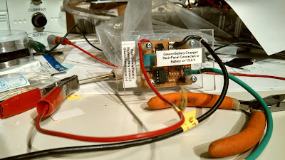
Figure 1:
The charge controller with connecting leads.

Controlling current flow without heat:

Here's the thing about efficiently switching current on and off:  If you have a switch, you need to have it firmly "on" so that the current flowing through it doesn't generate heat due to resistance - and a high-current power FET will do this nicely.  The one that I chose had no more than 0.02 ohms of "ON" resistance and with 10 amps, this would produce a measly 2 watts of heat.  Conversely, when the FET is off it isn't passing any current at all so it isn't even thinking about getting hot.

It's in that "in-between" state that the problem lies:  If there is resistance - say, from the FET not being turned on fully - it will immediately get hot and if one can't get rid of that heat, it will be destroyed.  One must switch the FET on and off quickly so that it spends as little time in that "in-between" state as possible.

On my first version of this controller using a TL431, this could happen fast enough that the FET was being turned on/off very quickly, spending too much of its time midway between "on" and "off" and getting hot.  After a few initial attempts to slow things down with the addition of some capacitors and adding a bit of hysteresis using a few resistors, I realized that in order to make it work it would have to get more complicated, so I decided to scrap the initial version for something "simpler."

Instead, I would use a computer!  See the diagram in Figure 3.

At first glance it would seem that the use of a computer was not going in the direction of avoiding complexity, but standing back for a moment let's take a look at what is needed for a simple PIC microcontroller-based solar charge controller:
  • A PIC.  I would use the 8-pin PIC12F683 which has an onboard A/D converter, watchdog timer and clock oscillator.
  • A voltage regulator.  To allow the PIC to run from the 12 volt battery being charged, I would use a 78L05 to provide 5 volts which I would also use as a voltage reference.
  • A power FET.  This would be used to connect/disconnect the solar panel from the battery, depending on the state-of-charge (voltage) on the battery.
  • A status LED.  Just because I could, I decided to use a red/green LED to indicate that the unit was powered up and actually doing something.  Separate LEDs could be used if that's all you have.
  • Other circuitry.  There was a 10-turn potentiometer for voltage calibration, a pair of transistors to drive the FET and a few miscellaneous resistors and capacitors.
The real magic was to be done in software and I decided to make it work like this:
  • Measure the voltage on the battery.
  • If the battery voltage is above 13.8 volts, disconnect the solar panel from the battery and make the status LED glow green.  Wait for at least 1/2 second before doing anything else - such as reconnecting the solar panel for additional charging.
  • If the battery voltage is below 13.2 volts, connect the solar panel to the battery and wait for at least 1/1000th of a second before doing anything else to the battery.  When in this state, make the LED glow red for at least 1/20th of a second (even if the battery was disconnected 1/1000th of a second later) so that even a brief flash would be more visible.
  • Every 5 seconds, the charging switch (FET Q3) would be opened very briefly and the device will measure the solar panel's open-circuit voltage.  If it was too low - which would happen if there was no sun - the unit would stop charging and indicate this to the user by briefly flashing the LED yellow every 2 seconds.
In other words, the unit could immediately (after 1/1000th of a second) disconnect the solar panel from the battery if the voltage on the battery were above the "full charge" voltage, but it would wait for at least 1/2 second before deciding to reconnect the solar panel if the battery were too low.   

(Note:  Practically speaking, R1/R2 and C3 slow the response to the changing voltage somewhat so it probably doesn't respond quite as fast as 1/1000ths of a second.)

Figure 2:
A close-up view of the controller in its protective case.

The reason for the immediate response if the voltage were on the high side would be to minimize the time that the battery and/or the equipment connected to it was exposed to voltages that might be in excess of, say, 14 volts.  If the battery to which the unit is connected, this is unlikely since the capacitance of the battery alone - not to mention the electrochemical processes - would prevent the voltage from increasing too rapidly.

The reason for the 1/2 second delay if the voltage were on the low site would be to allow the battery voltage to settle down when the charging current was removed, but also to prevent the FET from being turned on and off too quickly and too frequently.  As we know from above, if the FET is fully on or off it's not going to generate much heat at all and by minimizing the rate at which it will switch between those states, heat generation can be minimized.

These two thresholds (13.2 and 13.8 volts) weren't chosen by accident.  If a healthy 12 volt lead acid battery ever does reach 13.8 volts, it is guaranteed to be at least mostly (if not fully) charged. If this same battery is allowed to "float" (e.g. no load) at this same charge level, it will take some time to drift back down to 13.2 volts. If the battery still has a bit of charging to do it will rather quickly drop back down to (and below) 13.2 volts - particularly if there is a load.
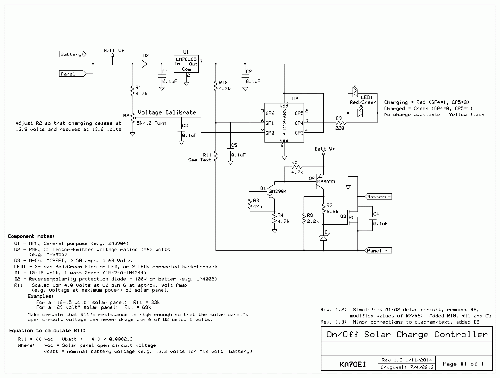
Figure 3.
Schematic diagram of the solar charge controller.  The circuit shown is intended for
"12 volt" (6-cell) lead-acid batteries.
It can be constructed using the PIC12F675 instead - see notes, below.
See notes and text for additional details about this circuit and its use.
Click on the image for a larger version.

So, there you have it, a very simple charge controller!

The .HEX files for programming a processor yourself:

Two .HEX files have been produced:  One for the PIC12F683 as described in the text, and another using the PIC12F675.  These files are NOT interchangeable or likely to be appropriate for other devices.

For the .HEX files, go to the page indicated by the link, below:
  
Web page with .HEX files for solar charge controller  (link)

If you cannot program a processor yourself and are interested in obtaining one, contact me.

Additional comments:

How it's connected to the battery:

As can be seen in Figure 1 large alligator clips are used to connect the battery.  Because the FET switch is in the negative lead, the positive terminal of the battery and the positive terminal of the solar panel are connected together at the battery.  It is recommended that short, heavy leads connect this unit directly to the battery to maximize charge efficiency and to best allow the controller itself to measure the battery voltage:  Long, skinny leads would cause a voltage drop, making the unit "think" that the battery was more-fully charged than it actually was.

A few warnings about the battery connection:

Because there is not extensive protection against high or reverse-applied voltages it is recommended that one connect the charge controller to the battery and then connect the solar panel, and when you are done, do the reverse - disconnect the solar panel then disconnect the battery.

Another extremely important point:  Make certain that the device being powered by the battery is firmly connected to the battery!

Because this device could put the full solar panel voltage across the terminals (in this case, 39 volts) a 12 volt device could be destroyed immediately by over voltage!  If you are using a battery that is in any sort of reasonable condition, this should never happen, but if your battery connections were loose - say, you had alligator clips from the device being powered connected to the battery and you had alligator clips from the charger connected to those clips - and the first set were to accidentally fall off, you could destroy your devices.

It is for this reason that you should always use the "permanent" connections to the battery to connect your devices (e.g. the battery posts.) so that you cannot accidentally have a connection to the solar panel without having the battery in the circuit.

Also, there's no "high-voltage" disconnect to protect the battery and the connected devices should the charge controller accidentally get "stuck" (due to the FET being damaged by lightning, for example) in the "on" state and continually applying current to the battery.  If this were to happen it is likely that the battery could be destroyed by gross over charging and the devices attached to it may be damaged as well.  In this circuit, the FET is reasonably well-protected against such things, certainly not against a very nearby or direct hit!


Explanation of the voltage thresholds:

In software, the battery is connected if its voltage drops below 13.2 volts and is disconnected if the voltage is higher than 13.8 volts:  In between these two voltages, the state is undetermined:  If the voltage had been below 13.2 volts, the panel will be connected (to charge the battery) but if the voltage had been above 13.8 volts, the panel will be disconnected.  Generally speaking, the panel will be connected as soon as the voltage is applied since it is unlikely that a battery that had been sitting for more than a few hours and not connected to a charger as its voltage will likely be well below 13.2 volts.

One could also use this same circuit for charging 6 volt and 24 volt systems as the ratio of the two voltages (on and off) would be correct for lead-acid batteries in this situations, too.  To do this, one may have to select an appropriate value for R1 as well as take into consideration the fact that U1, the voltage regulator, may not operate properly.

For example, at 6 volts unless a low-dropout regulator were used, or one used a different regulator to operate U2 at a lower voltage - say, 3.3-4 volts.  For 24 volts it may be wise to use a regulator that can withstand high voltages (>30 volts) for U1 or put in series with it a 10-15 volt Zener diode, taking care to leave the "top" end of R1 at the battery potential.   If you do change the voltage a which the PIC operates, you'll need to take into account that the voltage scaling resistors (R1/R2 for the battery voltage and R10/R11 used for monitoring the solar panel's open circuit voltage) are appropriately adjusted.

For other types of batteries (e.g. lithium-ion, NiCd or NiMH) this same sort of scheme could also be used, but very different charge-control schemes and voltage thresholds would have to be used to do this safely and this would imply a modification of the code.  Especially if you have several different types of battery chemistries, you may be better off having a small-ish lead-acid 12 volt battery to which these other chargers are connected to function as a low impedance "ballast".

In other words:  Do not use this circuit for any battery types other than lead-acid!

Why switch the panel in/out via its negative lead?

For this design I decided to put the power switching transistor in the negative lead of the solar panel rather than the positive lead and the reason for this is simple:  It was easier to do!

To have put it in the positive lead would have required one of two things:
  • The generation of a "boost" voltage.  I could have used an N-channel FET between the solar panel positive lead and and the battery's positive lead, but I would have trouble driving it.  The reason for this is that in order to turn on an N-channel FET fully, I would need to apply a gate voltage that would be at least 5-10 volts higher than the battery voltage.  Unfortunately, we cannot use the higher open-circuit solar panel voltage for this because if the FET were turned fully on, our solar panel V+ voltage would be the same as the battery V+ voltage.  In order to make this work we'd need to have a circuit that would generate a voltage that was higher than the positive battery voltage.
  • The use of a complementary device.  I could have used an opposite-polarity device such as a P-Channel power FET.  By doing so I could have "pulled down" on the gate/base and turned on the transistor, but there's a problem:  P-Channel FETs are harder to find, a bit more expensive, and typically have higher "ON" resistance than their N-Channel counterparts.  In other words, you can more easily and cheaply find N-channel FETs.
Why use a FET instead of a bipolar transistor in the first place?  Power FETs have the nice property that if you elevate the gate potential far enough "above" the source potential, they essentially turn into a low-loss "on" switch without requiring any drive current.  A bipolar power transistor, on the other hand, would require 1-5 percent (or more!) of the total device current being drawn through its base lead to make it fully conduct, and it would still drop more voltage across it and generate more heat than a FET.

Again, by switching the negative lead of the solar panel I could use a standard N-Channel FET:  Since the source lead of that FET would be pulled down and "away" from the +12 volt terminal of the battery (even to a potential that is negative with respect to the battery minus lead) by the solar panel - and since the PNP driving it was at the battery + potential, we already had a ready-made source of drive voltage for it.

How the circuit works:

U1, a 78LO5 3-terminal voltage regulator supplies a clean source of 5 volts for the microcontroller - and also serves as the voltage reference to determine the charge state of the battery.  The raw battery voltage is scaled first with R1 and then with potentiometer R2, the latter being adjustable so that the "on" and "off" thresholds for charging can be calibrated.

If U2, the PIC12F683 (or PIC12F675) microcontroller sees that the voltage is too low (nominally below 13.2 volts) its sets pin 5 (GP2) high which turns on NPN transistor Q1 which, in turn, pulls "down" on the base of PNP transistor, Q2 to turn it on.  Resistor R4 limits the base current in both Q1 and Q2 while R3 guarantees that if U2's output is in a high-impedance state (such as during startup) that Q1 is turned off by default:  R5 performs a similar function for Q2, respectively as well as speeding up the rate at which it can be turned "off".

When Q2 is turned on, approximately "Batt+" volts (nominally the battery voltage - in the 12-13 volt area) appears at its collector which pulls up on the junction of R7 and R8 which, if the sun is shining, was already at a voltage that is equal to the open-circuit output voltage of the solar panel minus the battery's present terminal voltage:  In the case of the solar panels chosen, the open-circuit, full-sun voltage is around 39 volts so if the battery is at 12.5 volts, the drain of Q3 will have been at -26.5 volts with respect to "ground" - the negative terminal of the battery, or close to the full 39 volts of the solar panel's open circuit voltage.

Pulling the gate of Q3 "upwards" (e.g. making it positive) will turn it on, connecting the negative lead of the solar panel to the negative battery lead.  At this point the gate voltage will drop to about 12-13 volts, but this is sufficient to keep the device chosen fully turned on.  Because the gate-source voltage could conceivably exceed 20 volts or so - the (typical) maximum rating for such a device - at the instant that we turn it on Zener diode D1 in conjunction with R7 form a simple shunt regulator to limit its maximum voltage to a safe level.

Once the voltage rises above 13.8 volts U2, the controller, sets Pin 5 low which turns off Q1 and Q2 and allows R6 to pull Q3's gate voltage down to its source voltage and turn it off, disconnecting the solar panel from the battery.  C4, a 0.1uF capacitor, is placed across the FET so that any "ringing" or transients generated by the FET's being turned on and off are suppressed as well as providing a degree of RFI and static protection.

For this circuit to work properly, Q2 must be rated for the voltages that it will encounter so an MPSA55 was used which has a rating of 60 volts.  Q3 must also be rated for the expected voltage, low "on" resistance and several times the maximum current expected from the panel so a 100 volt, 50+ amp device was used to provide plenty of margin.

The reason for the use of both Q1 and Q2 is so that one can apply the battery voltage to the gate of Q3 when it is "on" to make certain that its resistance (and loss) is as low as possible:  Were Q2 driven directly by U2, we could only attach its emitter to the +5 volt supply and it was turned on, only about 5 volts could have been applied to Q3's gate which, for "normal" N-channel power FETs, may not be enough to drive it into full conduction and minimize its ON resistance.

In looking at Figure 1 and Figure 2 you may note that there is no obvious heat sink on Q3.  In actual operation, with 5-9 amps of current, it ran only very slightly warm but there was plenty of convection coupling (air cooling) as well as heat conduction via the heavy wire (#10-#12 AWG) that was soldered directly to the tab of Q3, its Drain lead which, in turn, connects to the negative lead of the battery.

Added later (after the pictures were taken) is the circuit consisting of R10, R11 and C5.  Forming a voltage divider, this allows the measurement of the voltage across the solar panel when Q3 is turned OFF to determine if there is any usable light falling on the solar panel.  If there is not, the computer will keep the solar panel disconnected and occasionally flash LED1 yellow to indicate that there's presently no power available from the solar panel.  To do make this determination while it is charging (e.g. the LED is red) the panel will occasionally be disconnected for a very brief moment to measure the voltage across the panel.  Of course, if it is not charging (LED is green) it doesn't need to disconnect the solar panel at all to make this reading.

If the panel is being illuminated and Q3 is off, the "Panel -" voltage will go negative with respect to the PIC's ground and via R11, pull U2, pin 6 down from the +5 volt supply   If the voltage on pin 6 of U2 is below about 4.0 volts when the panel is disconnected via Q3 - which indicates that the panel is capable of providing at least some charging current - we know that it is worth attempting to charge the panel.  If the voltage is higher than 4.0 volts when the panel is disconnected via Q3 we can safely assume that there is too little light to bother with and this will put the controller in a mode where it will not attempt to charge the panel and cause the LED to flash yellow every two seconds or so.  (If you have two separate LEDs, both will flash at the same time.)

Calculating the value of R11:

Note that the value of R11 should be chosen for the type of panel to be used.  Nominally, the voltage at pin 6 of U2 should be 4 volts (or lower) at the voltage at which the panel outputs maximum power (this is usually listed in the specs) and R11 should be high enough that at when the panel is open-circuit in full sun, that maximum voltage (often noted as "Voc" in the specs) is not high enough to try to drag pin 6 below ground.

On the diagram are two values shown:  33k for a panel typically used to charge 12 volt batteries directly (e.g. maximum power at around 14-17 volts, 24 volts open-circuit, maximum) and 68k for the panels that we used here (29 volts at maximum power, 39 volts or so open-circuit.)  On the diagram the formula:

R11 = (( Voc - Vbatt ) + 4 ) / 0.000213

Is given.  Since the supply voltage is 5 volts - and we want 4 volts at Pin 6, we want 1 volt of drop across R10 which yields approximately 213 microamps as noted in the above equation.  Kirkhoff's law dictates that the same current must flow through R11 to obtain that same voltage drop across R10 so we add 4 volts to the difference between our expected solar panel open-circuit voltage and get about 31k:  33k is chosen since that is the nearest common resistor value, yielding a "low voltage cutoff" of about 16 volts open-circuit panel voltage.

The "Vbatt" term is one that we must approximate:  If we used precision, fixed resistors for R1/R2 we would know the precise divisor ratio and be able to calculate the battery voltage and subtract it from the open-circuit panel voltage - but since this circuit doesn't do that, we must pick R11 to suit our needs.  In general, if we assume Vbatt to be 13.2 volts, the charge-cutoff circuitry will work fine for a "12 volt" lead-acid battery regardless of its charge state - as long as it is above 6 volts or so since we must have at least enough battery voltage to power our PIC circuit.

Comments:
  • Charging a completely dead battery:  If you were to have this circuit connected to a completely dead battery, charging would never start since the PIC could not be powered from the battery.  Were this to happen - and the solar panel was producing power - one would temporarily connect the Panel - and the Battery - connections together to provide a "bootstrap" charge to the battery.  It may take several minutes for the battery to have enough charge voltage to keep the circuit operational - and this would be true only if the battery was good.  A few warnings if you do this:  Disconnect EVERYTHING ELSE from the battery as it may be bad, and the full panel voltage may appear across the battery if you connect it directly to the panel.  If you do connect the panel directly to the battery in this way, do not walk away - keep monitoring the voltage until it reaches the low-mid 12 volt area.  Finally, be careful when connecting/disconnecting battery connections as sparks may cause hydrogen/oxygen gas explosions.
  • If you were to use a 29 volt panel to charge a 12 volt battery (read below about the efficiency losses in doing so!) there would be no harm in keeping the battery connected if that panel's open circuit were allowed to drop to 16 volts or so - as might happen at dawn/dusk or if the panel were partially shaded or damaged.  At 29 volts, however, the voltage a pin 6 will attempt to go negative, but diodes within U2 will prevent it from going much below -0.6 volts.  While in some cases this excursion beyond the supply rails can cause unexpected effects on the PIC's A/D input MUX and affect other A/D channels, that did not seem to occur in the prototype and it functioned fine - but your results may differ.
  • When in "Inhibit charge" mode (e.g. open-circuit panel voltage too low and charging is discontinued) the prototype, using a 78L05, consumed about 5.5 mA average battery current.  Much of this is the quiescent current of the voltage regulator, but some of it is also the LED occasionally flashing yellow to indicate that it is in a "not charging" mode.  When charging, the circuit will consume around 25 mA, most of this being drawn by the LED and the circuitry that turns on Q3.

Set-up notes:

Setting this circuit up is slightly tricky, but not difficult if instructions are followed.
  • As noted above, please be aware of the hazards associated with high voltage and/or current!
  • Preset R2 to the middle of its range.
  • Connect a variable voltage power supply across the Battery (+) and Battery (-) terminals and set it for 13.20 volts.
  • When first connected, the LED will cycle Green-Red-Yellow if you are using a dual-color LED.  It may then be either a solid color, of flashing.  If it cycles RED-Green-Yellow the LED's leads are reversed!  If you used separate LEDs instead of a single, dual-color LED, both will be on instead of displaying yellow.
  • Make sure that the LED(s) is/are properly connected and/or identified via the power-up color sequence.
    • The colors represent:
      • Red = charging
      • Green = not charging
      • Yellow (brief flash) = Charging voltage not available.
  • With the power supply connected across Battery (+) and Battery (-) set to precisely 13.2 volts, adjust R2 so that the voltage on its wiper (which is also connected to Pin 7 of U2) is 51.6% of the 5 volt power supply's voltage.  If the power supply were precisely 5.0 volts, this would be 2.58 volts.  It is normal for the output of the 78L05 regulator to be between 4.9 and 5.1 volts due to manufacturing tolerances:  It is recommended that you measure it precisely and calculate the 51.6% voltage.  This sets the charge cut-in threshold voltage.
  • If you set the power supply voltage to precisely 13.8 volts, the voltage measured on U2 pin 7 would be 54.0% of the PIC's 5 volt supply voltage, or 2.70 volts.  This is the charge cut-out threshold voltage.
Operation notes:
  • Using the value specified for R11 (33k), if the battery voltage is 13.2 volts and the open-circuit solar panel voltage is below 16 volts, the unit will determine that there is not enough energy from the panel to effectively charge it and in this mode, the LED will be mostly dark, flashing yellow every 2 seconds.  (If you used separate LEDs, they would both light up during the flash.)  Every 5 seconds during charging, the unit will open Q3 and briefly measure the voltage - a process that takes less than 100 milliseconds.
  • If the open-circuit panel voltage is above 16 volts, normal charging will occur with Q3 being closed.  If the battery is discharged and its terminal voltage is below 13.2 volts, the LED will glow red.
  • Once the battery voltage has exceeded 13.8 volts, charging will be stopped, Q3 will be opened and the LED will glow green.
  • Once a battery has achieved full charge, it is normal for the LED to be mostly green, occasionally flashing red - perhaps as often as twice per second.  It is also normal for the voltage to stabilize near 13.2 volts and slowly move upwards over a period of hours or days:  At 13.2 volts, a 12 volt lead-acid battery is "mostly" charged.  Because this controller can only turn charging "on" or "off", it is rather difficult to precisely obtain a charge voltage.
If lead-acid batteries are used other than 12 volt lead-acid, the above steps would be modified accordingly, but note the following:
  • The input to U1, the 78L05, must be at least 6.5 volts for the circuit to work properly.
  • U1 cannot tolerate much above 30 volts, so accommodations must be made if this can happen to protect it.
  • Keep in mind the voltage ratings of Q2 and Q3:  The rating of each should be at least the battery voltage plus the open-circuit panel voltage for a good safety margin.
  • If a different voltage panel is used you will need to properly calculate the value of R11 as noted elsewhere in this text.
  • R2 would be adjusted to 51.6% of the 5 volt supply to set the threshold for the battery voltage  below which charging would be started.  Again, the termination of the charge occurs at 54.0% of the 5 volt supply.  If the battery voltage is increased, it may be convenient to increase the value of R1 appropriately to better-scale the threshold voltages within R2's adjustment span.

"No diode in series with the panel?!?"

It should be noted that there's no "reverse polarity" diode in shown on the diagram as being in series with the controller to prevent the battery's charge from being applied to the panel when the sun is absent.  As it happens, almost all modern, manufactured panels have these diodes built in, anyway - but it would be a good idea to closely check the  panel's specifications.

If, when you connect your panel (shaded from the sun, or in the dark) across your battery and you see more than a few 10's of milliamps flowing into the panel then you might consider adding a series diode to prevent this.

More Comments:
  • While an "MPPT" controller (see the very last section of this article, "By the way, what's an MPPT charge controller?" below, for an explanation) would have been nice, this just wasn't going to happen on such short notice so I threw together a simple "on/off" voltage controller to allow current to be safely thrown at the battery without worrying too much about overcharging it.
  • Charging a battery from a solar panel with a voltage that far exceeds the requirements is very inefficient.  As noted above, if one used a normal "12 volt" panel (those with an open-circuit voltage in the 17-22 volt area) this short of charging is much more efficient.
  • If you build/use this controller for yourself, remember that there are no guarantees that this circuit is either effective or safe.  YOU are responsible for becoming familiar with and implementing the appropriate safety measures and dealing with hazards associated with high voltages and/or currents.
  • Not shown in the diagrams/pictures are necessary fuses and other protection that one must include in a practical installation.


By the way, what's an "MPPT" charge controller?

The charge controller described here simply connect the solar panel to the battery to charge and then disconnects it when the battery has achieved full charge - essentially similar to the "old-fashioned" way solar panel chargers used to work.  Because solar panels act as a source of current, it doesn't really care if its output is shorted out or left open.

Given that our hypothetical solar panel that will output 9 amps at 29 volts we can see that at that voltage we could extract (9 amps * 29 volts =) 261 watts from it, but if we were to short out the panel we would get zero watts (e.g. 0 volts * 9 amps = 0 watts.)

With this on/off switch connecting/disconnecting our battery, we will obviously get 9 amps into the battery, but if the battery were at 13 volts and charging, that would only be (9 amps * 13 volts =) 117 watts of power - this, from a panel that could provide much more than this at a higher voltage.

Clearly we are leaving 144 watts "on the table" somewhere, so how would we make use of it?  One way would have been to charge two 12 volt batteries in series (for 24 volts) which would have yielded 234 watts (e.g. 9 amps * 26 volts assuming 13 volts per battery = 234 watts).  This is much better, but our equipment doesn't actually run on 24 volts and it would be awkward to drag along two 12 volt batteries, anyway.

The way around this is to have an intelligent switching voltage converter.

The way this works is that it has a computer (digital or analog) that will figure out, on the fly, how much current it can pull from the solar panel and automatically calculate the amount of power being pulled at the same time by doing the standards "volts*amps" calculation.


One way to do this is to slightly adjust the switching voltage converter - a circuit that can efficiently convert a higher voltage at lower amperage to a lower voltage at a higher amperage - so that it tries to output a little more current which, in turn, would cause the input to attempt to pull a little more current from the solar panel.  When it does this it does the "Volts * Amps = Watts" calculation of power  and if, when it increased the current being pulled from the panel, it actually did get more power, it would try to pull still more current from the panel, incrementally - but if less power was available, it would decrease the current incrementally to rediscover the optimal condition.  This method is called "Perturb and Disturb" as it constantly "hunts" to dynamically determine the optimal power available from the panel.

If, for some reason, the "volts * amps = watts" calculation showed that there was actually less power available when we attempted to increase the draw from the solar panel by trying to pull too much current and/or the solar panel's output has dropped due to cloudiness, setting sun and/or shading, it would incrementally back off on how much power it tried to pull - and keep doing so until it got to the point at which it, again, got to the maximum output from the panel.

In doing this slight incremental up/down and "feeling" to see if there is more power available from the solar panel, we would be able to extract the maximum amount of power from the panel based on the conditions at that instant.  This type of controller is called an "MPPT" or "Maximum Power Point Tracking" - so called because it constantly adjust itself and tracks the conditions of the charge source (the solar panel) to determine the maximum power that can be extracted from the solar panel and delivered to the load.

[End]

This page stolen from ka7oei.blogspot.com

Monday, May 6, 2013

Not all cells are created equal! (Shunt regulation of batteries...)

If you have ever had a device (and who hasn't?) in which several cells were connected in series to make a battery, you may have noticed something an unfortunate fact:  Not all cells are created equal!

If you have been curious enough to take a voltmeter to a battery and independently measure the voltage of each cell in a string of cells, you will likely have noticed that their voltage can vary quite a bit - particularly when the battery is old and/or nearly discharged.

This mismatch is inevitable:  Not all cells were made exactly the same when they were new and can vary by capacity (in amp/hours) and/or internal resistance.  As the battery ages, there is also the fact that each of these cells is in a slightly different environment:  Some are at the ends of the string while others are in the middle, surrounded by other cells and this can affect their temperature which, in turn, affects both their longevity and performance over time.

For the most part we ignore this problem when using conventional non-rechargeable cells such as Alkalines, ceding only to the recommendation that one uses the same type and brand of cells to best assure that they will be reasonably well matched to begin with.

For rechargeable cells, it's a different story!

In that case, we often live with that which we were given.  Since it is likely that one will be (re)-using such cells for a much longer period of time than "primary" (non-rechargeable) cells, the initial match amongst the cells will inevitably diverge over time as the cells degrade at different rates, for different reasons.  For many types of cells (e.g. NiCd and NiMH) we ignore the problem at our peril - particularly with NiCds - and it is the chemistry that is oft-blamed for longevity issues rather than the way that they are applied in the first place!

There is one place where we can easily make a difference in how "equally" the cells are charged, discharged and maintained:  Lead-Acid cells.

The "UPS" Example:

One clear example of this is a typical small-large UPS (Uninterruptable Power System).  At my work, we have a 300kVa (yes, that's well over 200 kilowatts!) that uses two parallel strings of forty "12 volt" batteries (about 542 volts, nominal), for a total of 80 batteries.  Left to their own devices, the voltages on these batteries will inevitably diverge over time from the average 13.55 volts with some batteries going down to about 13.2 volts and others rising up close to 14.0 volts!

Again, this divergence is inevitable, particularly considering that the self-discharge and leakage currents that are responsible for these divergences are typically in the range of 1-20 milliamps for the (nominally) 100 amp-hour battery!  In other words, it takes VERY LITTLE difference between batteries to cause a seemingly radical change in float voltage!

This divergence actually poses a problem:
  • Much below 13.4 volts, the battery is not fully-charged and is more prone to sulfation and loss of capacity.
  • Much above 13.65 volts, the rate at which gasses are generated increases.  Even though typical UPS batteries such as VRLA (Valve-Regulated Lead-Acid) are able to contain and reabsorb gasses to an extent, continuous/excessive gas generation will likely lead to the slow loss of electrolyte and thus shorten the life of the battery.
In either of the above cases, there will be a bias toward shortened battery life and because such a system is only as strong as the weakest cell in the string, reliability and longevity can be impacted!

Even if you don't have such an extreme case as 40 batteries in series, it is common to find small-ish UPSs that use 24 (2 batteries) or 48 (4 batteries) volt systems and these, too, can suffer inequality - particularly if one uses "pulls" (e.g. aging, but still usable batteries) from larger UPS systems.

Fortunately, there is an easy solution to part of this problem:  A shunt regulator.

While we really can't do too much about the voltage of the individual 2 volt cells within a 12 volt lead-acid battery because the interconnects between cells is (usually) inaccessible, we might as well do what we can to help mitigate the problem by regulating the float voltage of the 12 volt battery overall.

Zener Shunt regulator:
Figure 1:
Zener-based shunt regulator.
Click on the image for a larger version.

The simplest system is that shown in Figure 1 which consists of just a resistor, an LED, a Zener diode and a few "ordinary" silicon diodes.

In this circuit, the Zener diode (ZD1) has a fairly sharp "knee" at 10-11 volts such that a small increase in voltage causes a very rapid increase in current.  Included is a series LED - mostly used as an indicator of current flow - that also has a sharp diode "knee" response along with a current-limiting resistor that also serves to soften the curve of the knee somewhat.  Finally, there are several ordinary diodes in series, the tap between each can be adjusted for precise adjustment of the float voltage.  While it would be possible to put many (say, 18-22) ordinary diodes in series to achieve a similar drop, this gets gets to be awkward and cumbersome and the shunt voltage of such a system can change significantly with temperature.  The system described here - while not perfect - is a reasonable compromise between performance and simplicity.

While the resolution of the 0.6 volt taps between diodes may seem to be a bit coarse, the actual effect on the float voltage is much less than this owing to the fact that the aforementioned knee isn't ultra-sharp and the amount of current required to achieve a certain amount of voltage drop isn't necessarily a linear curve, anyway!  As noted in the above diagram, small tweaks may be accomplished by tweaking the resistor value, but I rarely found this to be necessary in practice.

As you might suspect, the above circuit is going to have the effect of clamping down the voltage of a battery that would tend to float high (above 13.55-13.6 volts) but by doing so, it will (indirectly) bring up the voltage of those batteries that would tend - because of internal leakage currents - to be on the low side.

What is surprising to many people is that just a few 10's of milliamps is all that is required to equalize batteries that are in reasonable health!  The initial reaction is often one of "What good can the current through a few LEDs do to equalize the voltage on a string of 100 amp-hour batteries" but this belies the nature of the problem in the first place!  Of course, if one of the batteries is in particularly bad shape (high internal resistance or high leakage/self discharge current) then all bets are off - and this particular battery is probably at the end of its life, anyway!

Others may question the assertion of a nominal "13.55" volt setting as this "optimum" voltage tends to vary with temperature as well as whom one might ask, but it's hard to argue that this isn't, in fact, a "reasonable" voltage for the vast majority of conditions that one might encounter:  Anyway, it would be more harmful to deviate much from this voltage for long periods of time by ignoring the problem altogether!

Construction:

As can be seen from Figure 2, this circuit is quite simple:  The components are simply soldered in series with a piece of red wire and alligator clip forming the positive side.

For the negative side, a short, black jumper with a clip lead on each end is used:  One end goes to the negative terminal of the batter while the other is used to select which diode tap (and thus the shunt voltage) is to be selected.

While would could "permanently" attach the shunt regulator to the battery with a ring lug on each of its terminals, I chose not to do this since adding an extra "layer" of conductor on the battery bank of the 300 kVa UPS could contribute to added terminal resistance at the battery - a particularly important fact when it is considered that the batter current could easily exceed 100 amps!  The use of the humble spring-loaded clip lead has proven to be more than adequate and is easily removed/installed when the battery bank is maintained.  If, however, your battery bank is mobile (say, in an RV) or of modest size (say, a few thousand watts or less) then it might be more appropriate to use ring lugs as well as wire ties and electrical tape to make sure that nothing can shift and short out during transport.


Adjusting the voltages:

As noted in the diagram above, setting the precise float voltage can be a bit tricky as it can take several hours for things to settle after an adjustment.

Figure 2:
Zener shunt regulator.
Click on the image for a larger version.
It is also recommended that one actually slightly overshoot on the amount of current required to bring down the the voltage of those batteries that tend toward the "high" side and even cause those batteries that were slightly low in voltage due to higher internal leakage to come up in voltage - even rise slightly above the desired voltage.  In this case, one would also equip those "low" batteries with a shunt regulator, but one would necessarily set the shunt current commensurately lower to make the voltage equal.  In other words, it's a good idea to have at least a little shunt current across all batteries in the series string as this will help assure overall stability over time.

One should remember that the voltage on each battery should be approximately that of the average voltage of the charging system - that is, the overall float voltage divided by the number of batteries.  For example, if your UPS float charges the battery bank at 54.10 volts, you would want to set the average float voltage 13.525 volts on each battery - but, of course, it could not be higher than this!  Some UPSs have the means to adjust the precise float voltage - either with a potentiometer (sometimes unlabeled on a circuit board) or via a menu setting, and if  the average voltage turns out to be much outside the range of 13.40 to 13.65 volts, you might consider figuring out how to do this!

Observations over time:

In a number of systems - including the 300 kVa UPS - I've used this (and similar) shunt systems for over a decade and have achieved extremely good results and longevity with the battery bank.  As it happens, the 300 kVa UPS's battery bank is equipped with a system that periodically does internal resistance measurements of each of the batteries within the bank and that over time, this value of internal resistance has been correlated with the actual health of the batteries - both in terms of high-current load test capability and a longer-term amp-hour capacity test.

With good-quality 100 amp/hour VRLA batteries, it is typical to get 5-7 years of life from a battery before its internal resistance exceeds our threshold (about 5 millihoms) and it is pulled from service, at which point its capacity is typically in excess of 70 amp/hours and it will provide at least another 2-4 years in less-critical backup service.

By amassing data for each and every battery over its lifetime, I have observed a significant correlation with its float voltage and longevity:  There seems to be relatively little penalty for running the battery slightly low in voltage (e.g. 13.40 volts) but there is a statistical disadvantage to having it above 13.65 volts!

Charge/Discharge concerns:

When this system has been described, one concern often raised is that of charging batteries that may be somewhat unequal in series strings.

First of all, this is inevitable as it is simply not practical to keep all cells precisely matched and when the battery bank is being charged, it will always happen that some cells will be overcharged before others achieve full charge.  While there is nothing that we can do about this, having a degree of extra shunt current can reduce the time during which a particular battery is exposed to higher-than-desirable voltages.  Again, within the 12 volt battery, we can also do little about the state of the individual 2 volt cells within, but we can at least minimize the impact by regulating the battery, overall.

Practically speaking, it has been observed from monitoring the computer that keeps track of the state of the individual batteries that they actually achieve equilibrium quite quickly - typically within 24-36 hours - after a fairly significant discharge if equipped with such a shunt regulator system.

Other voltages:

It just happens that most of the system with which I deal use 12 volt batteries, but the shut system described could be easily adapted for 6 volt (e.g. golf cart) type batteries or, possibly, individual 2 volt cells, although the latter would require a bit more precision!

Final comments:

The Zener-based shunt system described here is about as simple as it could be in terms of construction and adjustment and still be reasonably consistent over time, under varying loads, and at different temperatures.  I did, in fact, use this system for a number of years on the 300 kVa UPS mentioned, but I gradually changed out the Zener-based shunt regulators with others based on the TL431 shunt regulator IC - but I still use the Zener-based regulators on smaller, multi-battery systems and continue to experience excellent results!

Update:

There is an update to this article:  Shunt Regulation of series-connected lead-acid batteries to equalize the voltage link.  That article describes a simple shunt regulator that can be used for both 6 and 12 volt batteries that will do a better job than the circuit described above.


[End]

This page stolen from ka7oei.blogspot.com