Showing posts with label QRSS. Show all posts

Wednesday, December 6, 2017

KA7OEI now QRV on 630 and 2200 meters

Figure 1:
The LF/MF transmit station, configured for 630 meter operation.
At the time this picture was taken I had not yet completed the gear and
put the various pieces in their boxes, hence the mess of clip-leaded-
together modules sitting on my workbench.  Not visible is
the low-pass filter in the power amplifier box or the thermocouple-type
RF ammeter.  The pictured 630 meter variometer has been supplanted
with a "new" one wound with 660/42 Litz wire for lower loss (see Figure 6).
Click on the image for a larger version.
It so-happened that I had a few days off around Thanksgiving and I took this time to throw together a fairly simple transmit converter for the "new" amateur LF and MF bands - notably 2200 and 630 meters.  Having had already obtained my approval from the UTC to operate on both of these bands, I was "good to go".

It took only two evenings to put together the transmit converter and power amplifier as I had the parts on hand - and none of them were particularly exotic.  While the transmit converter will be described in greater detail in a future post, the signal path for the transmitter is approximately thus:

(See the block diagram in Figure 2, below.)
  • A 5 MHz IF is used, allowing a "broadbanded" FT-817 (with TCXO) to serve as the exciter.
  • The 5+ MHz signal (about 5137 kHz for 2200 meters, 5475 for 630 meters) is mixed (using a 74HC4066) with a 5 MHz local oscillator (a 10 MHz OCXO divided-by-two) to yield frequency-stable LF/MF signals.
  • A low-power post-mixer amplifier boosts this signal to a level capable of driving the power amplifier.
  • A single-ended MOSFET-based broadband power amplifier, running on 12-30 volts, provides between 10 and 50 watts of RF at either 630 or 2200 meters.  Because the transmit converter is broadband, it is agnostic to the operating frequency meaning that one needs only use the appropriate low-pass filter to change bands.  (The 630 meter low-pass filter is always in line - another filter is added for 2200 meter operation.)  This power amplifier is designed to be driven by either the transmit converter or another device, such as a QRP Labs Ultimate 3S beacon transmitter configured for these bands.
  • The 50 ohm output of the power amplifier goes to a tapped autotransformer wound on what is probably an FT-240-61 toroidal ferrite core and is used to match the transmitter's output to input resistance of the loading coil.
  • Also in the drawing is a relay the disconnects the loading coil from the autotransformer when not transmitting.  This was necessary to prevent the transmit antenna from "sucking out" some of the receive signal being intercepted by my E-field whip and also to prevent the transmit antenna from conducting "house noise" from the transmitter onto the transmit antenna which gets coupled into the receive antenna, reducing ultimate sensitivity. Not shown in the drawing is a 100k resistor connected between the "relay" side of the variometer and ground that bleeds static when the relay is open.
  • The loading coil, placed in series, cancels out the capacitive reactance of the antenna system.  For 630 meters my antenna requires about 230uH while about 2.5mH is needed to resonate the same antenna at 2200 meters.
Figure 2:
Block diagram of the 630 and 2200 meter transmit chain.  The transmit converter is broadband, capable of operating
from below 100 kHz to at least 500 kHz which means that one need only provide appropriate matching and low-pass filters to operate on either band. Not shown is a 100k static bleed resistor on "relay" side of the variometer and ground.
Click on the image for a larger version.

When I made my first-ever transmission I had not yet constructed the variometer, but I fished around in my "box-o-inductors" and found several Litz-wound ferrite inductors that were probably rescued from some scrapped TVs or computer monitors and wiring enough of these in series I was able to achieve  resonance with about 750mA of antenna current.  On the very first WSPR transmission I managed to be "heard" by several stations (See Figure 3, below.)
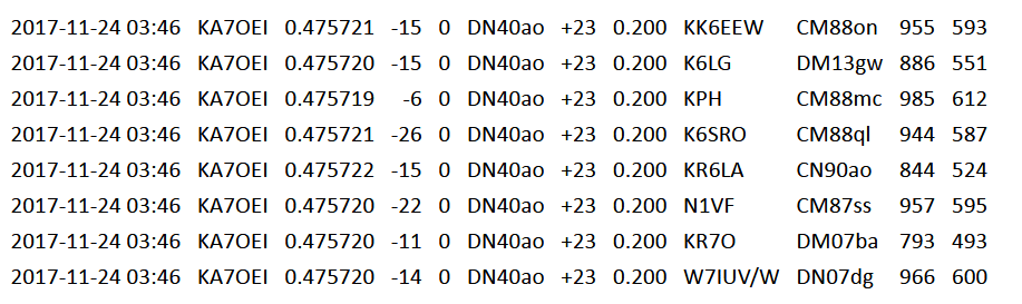
Figure 3:
A screen shot (from WSPRnet.org) of the very first 630 meter WSPR transmission that I made with the badly-kludged loading coil.
Not too bad for a temporary lash-up!
On the next night, after observing a few stations engaging in JT-9 QSOs, I answered a CQ by VE7SL and he replied, giving me a signal report of -22dB while I gave him -19dB.  This was quickly followed by two other QSOs as both W7IUV and NC0B noticed the "new guy" on the band!

Over the next several days I got around to constructing the "new" variometer depicted in Figure 4 and this boosted my antenna current to about 1.25 amps - a theoretical improvement of about 4.4dB with more QSOs to follow - including 2.5 (one "partial") CW contacts on the band.  After operating for a while it became apparent that, for the most part, I could work anyone that I could "hear".

A few days later I constructed yet another variometer for 630 meters - this time using some 660/42 (e.g. 660 strands of 42 AWG) Litz wire which reduced the skin-effect losses by a significant amount and this, along with minor improvements of the ground system, decreased losses and resulted in a further increase of antenna current to a bit over 2 amps - a theoretical ERP improvement of more than 8.5dB as compared to my original configuration. The measured resistance at the input of the 630 meter Litz coil is about 13.5 ohms, implying an overall antenna system efficiency roughly 1% - but still enough to work quite a few stations with a few 10s of watts of RF.

Figure 4:
 The "Mark 1 version of the 630 meter variometer.  This device is wound
on "4 inch" ABS triple-wall sewer pipe using 22 AWG insulated hookup
wire.  Inside is "3/4-inch" ABS waste pipe (actual O.D. about 1-1/8")
that forms the rotatable portion of the variometer.  This unit has an
adjustment range of approximately 175-235 uH.
Click on the image for a larger version.
The "Q" of the antenna system+Litz wire coil is now such that if I QSY from 475.75 kHz for WSPR operations down to about 475.0 kHz for JT-9 I actually see noticeable drop in antenna current until I readjust the variometer, but if I QSY from 475 kHz down to 473 kHz for CW operation the antenna current plummets to a few hundred milliamps and I absolutely must retune!

As is the custom on both the LF and MF bands, my WSPR signal reports not the transmitter power, but rather the estimated EIRP.  I've typically been reporting 0.5 watts (+27dBm) which, assuming about 25 watts of RF power, implies an antenna efficiency of about 2% which, while in the general ballpark, may still be a bit optimistic.  With the recent changes/improvements in my system (mostly improving the grounding, radials and counterpoise network) I will have to re-analyze my estimated system efficiency.

Operation on 2200 meters:
Figure 5:
Antenna and ground system of my LF/MF TX antenna system.  The
yellow line represents the outline of the "Lazy Loop" - a horizontal HF
antenna fed with 450 ohm window line with both conductors of the
feedline being tied together and fed as a tophatted vertical on LF/MF.
The total circumference of this antenna is about 215 feet (65 meters) -
dimensions mostly dictated by the locations of trees at an average
height of roughly 30 feet (9 meters).
The red lines show the extent of my ground/radial system showing
extra wires, including sections of chain-link fences with electrically-
bonded sections and wires buried in the ground, including an
abandoned CATV line.  The roofs of both the house and garage are
metal which are ultimately tied into the ground/radial network.  There
are several ground rods near the feedpoint of the antenna to which
all of the grounds/radials are connected.
Click on the image for a larger version.

I have since wound yet another variometer (visible in Figure 6, below) - also on 4" ABS pipe - for 2200 meters.  This coil, adjustable from about 1.7-2.0mH, uses the same 22 AWG hook-up wire as my original 630 meter loading coil.  As it turned out this coil, by itself, doesn't have quite enough inductance to resonate my antenna at 137 kHz so I place the other two 630 meter coils in series with it.  As compared to the 630 meter loading coils, it is somewhat lossy, but I am able to obtain about 900mA of antenna current:  Not surprisingly, this coil runs slightly warm in operation due to the losses - but these are, no doubt, minor in comparison with the ground losses.

Update - 12 December, 2017:  After improving the ground system my antenna current is now around 1.1 amps on 2200 meters, implying an improvement of at least 1.7dB from current alone.  The actual far-field improvement, based on readings seen from monitoring stations on WSPR, appears to be in the area of 2-3dB.

The measured resistance at the input of this loading coil is about 43 ohms implying an overall antenna system efficiency of well under 0.1%.   Based on estimated antenna efficiency, I've configured WSPR to report my ERP as 50mW, which assuming a transmitter output power of about 25 watts implies an actual antenna efficiency of about 0.2% which is probably very optimistic!

Update - 5 May, 2018:  After some old-fashioned number-crunching, several antenna simulations and comparing my signal to other beacons of "known" EIRP I've revised my estimate of radiated power to be closer to 20 milliwatts, even after taking into account that I've increased my amplifier's output power to between 60 and 80 watts.  The previously-optimistic calculations assumed lower ground (and other losses - such as those due to nearby vegetation) than I originally thought that I had.

* * *

Not surprisingly, operation on 2200 meters - even at this power level - can be a bit hazardous.  With the rather low antenna capacitance the voltages on the feed are quite high - an estimated 5000-8000 peak volts!  What this means is that the feed wire has to be kept well clear of other conductors or else corona will occur, sapping transmit power, filling the room with ozone and becoming a potential fire hazard.  Fortunately, at this modest power level - and with the current-regulated power supply that I'm using - almost any sort of fault will detune the antenna system to the point that the high voltage will all but disappear and/or the power supply will go into current limiting and effectively shut down the transmitter.

Figure 6:
Left to right:  The original 630 meter variometer (seen in figure 4
wound with 22 AWG stranded wire , the new 630 meter wound with
660/42 Litz wire and the 2200 meter variometer, wound with the
same 22 AWG stranded wire and insulated with PET tape to allow it
to withstand the high voltages.  In the lower right corner is the
autotransformer wound on an FT-240 ferrite core.  With my current
(pun intended!) antenna I must put all three of these variometers in
series to resonate the system at 2200 meters.
Click on the image for a larger version.

Despite this simple arrangement I've managed to be "heard" by at least seven other stations in the western U.S. and Canada using WSPR to date, but I've not yet made any 2-way contacts.  The relative scarcity of stations that listen or transmit on 2200 meters - coupled with my rather weak signal - means that a contact will probably have to be arranged and conducted using a weak signal mode like JT-9 or QRSS.

Improvements:

There are plenty of improvements to be made, most notably getting the feed of my antenna a bit higher, laying out a few additional ground wires to further-reduce losses and improving the variometer for 2200 meters - but there are only so many things that I can do on my relatively small city lot.  This entire arrangement has so far been precariously sitting on my workbench meaning that the high RF voltages are also also nearby, just waiting to leap out at me when I reach over to tweak a variometer.

At some point I'll "remote" the matching network outside, but I need to get/build a few other items first, namely some stepper motors, control circuity, more vacuum relays and a means of remotely monitoring the antenna current.

Comment:  Despite having the feedpoint in my shack, I've not had any problems at all with transmit RF getting into computer speakers or other devices in my house.

* * * * * * * *

My recent operation, as of the date of this post, seems to be the only actively transmitting station on either 630 or 2200 meters in Utah.  I have been running WSPR on 2200 meters most of the time, occasionally switching to 630 meters in the local evenings when the activity level on that band is highest.

If you are QRV on 2200 or 630 meters and would like to arrange a CW, JT-9 or QRSS contact with me, or if you are interested in just "hearing" my signal (via your ears or with a computer+sound card) drop me a line using my callsign at arrl dot net.

Other entries on related topics found at this site:
Other web sites that have information on 630 and 2200 meters: 

This list is by no means comprehensive.  Peruse the "links" sections on the sites below for even more information.
  • NJD Technologies - link  - This web page has a wealth of information related to 630 meter operation, propagation and reports of activity, plus lists of known-active operators on both 630 and 2200 meters.  This web site also has many links to others that have credible information on LF and MF band topics.
  • W1TAG's web site - link  - John, W1TAG, has long been an experimenter and operator on the MF and LF bands.  This site has details on equipment both for operating and measuring performance at these frequencies.
  • W1VD's web site - link - Jay, W1VD, has long been an experimenter on the LF/MF bands and this page offers a lot of information on equipment for transmitting and receiving on these bands.
  • Antennas by N6LF - link - The callsign gives  you the clue that this guy likes LF/MF operation.  This page includes detailed information on LF/MF antennas and how to characterize/improve them.

[End]

This post stolen from ka7oei.blogspot.com

Monday, August 28, 2017

Monitoring the "CT" MedFER beacon from "Eclipse land"


Figure 1:
The MedFER beacon and vertical, tophatted
antenna on the metal roof of my house, attached
to an evaporative ("swamp") cooler.
Click on the image for a larger version.
I must admit that I was "part of the problem" - that is, one of the hordes of people that went north to view the August 21, 2017 eclipse along its line of totality.  In my case I left my home near Salt Lake City, Utah on the Friday before at about 4AM, arriving 4 hours and 10 minutes later - this, after a couple of rest and fuel stops.  On the return trip I waited until 9:30 AM on the Wednesday after, a trip that also took almost exactly 4 hours and 10 minutes, including a stop or two - and I had no traffic in either case.

This post isn't about my eclipse experiences, though, but rather the receiving of my "MedFER" beacon at a distance of about 230 miles (approx. 370km) as a crow flies.

What's a MedFER beacon?

In a previous post I described a stand-alone PSK31 beacon operating just below 1705 kHz at the very top of the AM broadcast ("Mediumwave") band under FCC Part 15 §219 (read those rules here).  This portion of the FCC rules allow the operation of a transmitter on any frequency (barring interference) between 510 and 1705 kHz with an input power of 100 milliwatts using an antenna that is no longer than 3 meters, "including ground lead."  By operating just below the very top of the allowed frequency range I could maximize my antenna's efficiency and place my signal as far away from the sidebands and splatter of the few stations (seven in the U.S. and Mexico) that operate on 1700 kHz.
Figure 2:
Inside the loading coil, showing the variometer, used to fine-
tune the inductance to bring the antenna system to
resonance.  This coil is mounted in a plastic 5-gallon
bucket, inverted, to protect it from weather.

As described in the article linked above, this beacon uses a Class-E output amplifier which allows more than 90% of its DC input power to be delivered as RF, making the most of the 100 milliwatt restriction of the input power.  To maximize the efficiency of the antenna system a large loading coil with a variometer is used, wound using copper tubing, to counteract the reactance of the antenna.  The antenna itself is two pieces:  A section, 1 meter long, mounted to the evaporative cooler sitting on and connected to the metal roof of my house and above that, isolated from the bottom section is an additional 2-meter long section that is tophatted to increase the capacitance and reduce the required amount of loading inductance to improve overall efficiency.

As it happens, the antenna is mounted in almost exactly the center of the metal roof of my house so one of the main sources of loss - the ground - is significantly reduced, but even with all of this effort the measured feedpoint resistance is between 13 and 17 ohms implying an overall antenna efficiency of just a few percent at most.

Figure 3:
The tophatted vertical antenna, loading coil and transmitter, looking up
from the base.  In the extreme foreground along the left side of the
picture can be part of the weather-resistant metal box that
contains the transmitter.
Click on the image for a larger version.
Originally intended only as a PSK31 beacon, I later added the capability of operating on 1700 kHz using AM and being able to do on/off keying of the carrier at the original "1705" kHz PSK31 frequency, permitting the transmission of Morse code messages.  For the purpose of maximizing the likelihood of the signal being detected, this last mode - Morse - I operate using "QRSS3", a "Slow" Morse sending speed where the "dit" length of the characters is being transmitted is 3 seconds - as is the space between character elements - and a "dah" and the space between characters themselves is 9 seconds.

Sending Morse code at such a low speed allows sub-Hz detection bandwidths to be used, greatly improving the rejection of other signals and increasing the probability that the possibly-minute amount of energy reaching the receive antenna may be detected.

Detecting it from afar:

Even though this beacon had been "received" as far away as Vancouver, BC (about 800 miles, or 1300 km) using QRSS during deep, winter nights, I was curious if I could hear it during a summer night near Moore, ID at that 230 mile (370km) distance.  Because we were "camping" in a friend's yard, we (Ron, K7RJ and I) had to put up an antenna to receive the signal.

The first first antenna that we put up received strong AC mains-related noise - likely because it paralleled the power line along the road.  Re-stringing the same 125-ish feet (about 37 meters) of antenna wire at a right angle to the power line and stretching out a counterpoise along the ground got better results:  Somewhat less power line noise.  It was quickly discovered that I needed to run both the receiver and the laptop on battery as any connection to the power line seemed to conduct noise into the receiver - probably a combination of noise already on the power line as well as the low-level harmonics of the computer's switching power supply.

I'd originally tried using my SDR-14 receiver, but I soon realized that between the rather low signal levels being intercepted by the wire - which was only about 10 feet (3 meters) off the ground - and the relative insensitivity of this device, I wasn't able to "drive" its A/D converter very hard, resulting in considerable "dilution" of the received signals due to quantization noise.  In other words, it was probably only using 2-4  bits of the device's 14 bit A/D converter!

I then switched to my FT-817 (with a TCXO known to be accurate to better than one part-per-million) which had no troubling "hearing" the background noise.  Feeding the output of the '817 into an external 24 bit USB sound card (the sound card input of my fairly high-end laptop - as with most laptops - is really "sucky") I did a "sanity check" of the frequency calibration of the FT-817 and the sound card's sample rate using the 10 MHz WWV signal and found it to be within a Hertz of the correct frequency and then re-tuned the receiver to 1704.00 kHz using upper-sideband.  It had been several years since I'd measured the precise frequency of my MedFER beacon's carrier, last being observed at 1704.966 kHz, so I knew that it would be "pretty close" to that value - but I wasn't sure how much its crystal might have drifted over time.

For the signal analysis I used both "Spectrum Lab" by DL4YHF (link here) and the "Argo" program by I2PHD (link here).  Spectrum Lab is a general-purpose spectral analysis program with a lot of configurability which means that there are a lot of "knobs" to tweak, but Argo is purposely designed for modes like QRSS using optimized, built-in presets and it was via Argo that I first spotted some suspiciously coherent signals at an audio frequency of between 978 and 980 Hz, corresponding to an RF carrier frequency of 1704.978 to 1704.980 kHz - a bit higher than I'd expected.

As we watched the screen we could see a line appear and disappear with the QSB (fading) and we finally got a segment that was strong enough to discern the callsign that I was sending - my initials "CT".

Figure 4
An annotated screen capture of a brief reception, about 45 minutes after local sunset, of the "CT" beacon using QRSS3 with the "oldest" signals at the left.  As can be seen, the signal fades in so that the "T" of a previous ID, a complete "CT" and a partial "C" and a final "T" can be seen on the far right.  Along the top of the screen we see that ARGO is reporting the peak signals to be at an audio frequency of 978.82 Hz which, assuming that the FT-817 is accurately tuned to 1704.00 kHz indicates an actual transmit frequency of about 1704.979 kHz.

As we continued to watch the ARGO display now and again we could see the signal fade in and out and be occasionally clobbered by the sidebands of an AM radio station on 1700 kHz - at least until something was turned on in a nearby house that put interference everywhere around the receive frequency.

The original plan:

The main reason for leaving the MedFER beacon on the air during the eclipse and going through the trouble of setting up an antenna was to see if, during the depth of the eclipse, its signal popped up, out of the noise - the idea being that the ionospheric "D" layer would disassociate in the temporary darkness along the path between my home where the eclipse would attain about 91% totality and the receive location within the path of totality, hoping that its signal would emerge.  In preparation for this I set up the receiver and the ARGO program to automatically capture - and then re-checked it about 5 minutes before totality.

Unfortunately, while I'd properly set up ARGO to capture, I'd not noticed that I'd failed to click on the "Start Capturing" button in ARGO and the computer happily ran unattended until, perhaps, 20 minutes after totality, so I have no way of knowing if the signal did pop up during that time.  I do know that when I'd checked on it a few minutes before totality there was no sign of the "CT" beacon on the display.

In retrospect, I should have done several things differently:
  • Brought a shielded "H" loop that would offer a bit of receive signal directionality and the ability to reject some of the locally-generated noise and would have saved us the hassle of stringing hundreds of feet of wire through trees.  Some amplification with this loop would also have helped the SDR-14 work properly.  Alternatively, a simple active whip (such as a PA0RDT "mini-whip") could have been built and used, its location chosen for lowest noise pick-up.
  • Actually checked to make certain that the screen capture was activated!
  • Record the entire event to an uncompressed audio (e.g. ".WAV") file so that it could be re-analyzed later.
 Oh well, you live and learn!

P.S.  After I returned I measured the carrier frequency of the MedFER beacon using a GPS-locked frequency reference and found it to be 1704.979 kHz - just what was measured from afar!

[End]

This information stolen from ka7oei.blogspot.com

Thursday, January 12, 2017

A low power PSK31 transmitter using a Class-E power amplifier and envelope modulation

Back in 1999, not too long after the first appearance of PSK31, I decided that I wanted to construct a beacon transmitter that would operate using this mode - but at the time the only practical means of generating PSK31 was with a computer, a sound card and an SSB transmitter.  Not wanting to tie up that much gear for this purpose I set about to use the PIC16C84 microcontroller, which was popular among the homebrew builders at the time.

By this time the AM broadcast band had (relatively) recently been expanded up to 1705 kHz but very few stations occupied the new 1605-1705 kHz segment.  In perusing the FCC rules I noted that Part 15 §219 had been modified to allow low-power experimental operation (100 milliwatts DC input with a size-limited antenna) in this new segment and I decided that with the lack of activity in this frequency range that it was a good time to put up a "MedFER" (Medium Frequency Experimental Radio) beacon.
Figure 1:
The "Balanced Modulator" (Baseband) version of the PSK31
transmitter/exciter.  Built to test a concept, it has a few flaws,
but it did work.
Click on the image for a larger version.

The balanced modulator method

Upon investigating various methods of producing a PSK31 signal I experimented with the generation of a bipolar baseband signal that could be applied directly to a balanced mixer.  While this method worked well it had the problem than it required that all following stages be linear.

A diagram of the prototype of that transmitter may be seen in Figure 1.  For this transmitter a crystal-controlled oscillator is constructed using two transistors (Q1, Q2) and the output is buffered by U3, a 74HC00 quad NAND gate.  The frequency used for this circuit was unimportant as it was a "proof of concept" and I (think that I) used a 4.9152 MHz crystal which, although not in any amateur band, still allowed an "across the room" reception with a short length of wire as an antenna.  Following the first U3 NAND buffer the remaining sections are used to provide a two phase signal with the output split 180 degrees which fed a very simple balanced modulator consisting of just two diodes, a few capacitors and some resistors.

To provide modulation a PIC16C84 was used to provide a 32-step staircase modulation using PWM techniques as this (now ancient) part had no PWM peripherals.  This PWM output, done using "bit-bang" software with a "NOP-tuned" interrupt service routine operated at a frequency of 1 kHz, which is exactly 32 times that of PSK31's 31.25 Hz baseband frequency.  The output was filtered with a two stage R/C low-pass filter network consisting first of a 4.7k resistor and 0.1uF capacitor followed by a second stage with a much higher impedance consisting of a 150k resistor and 0.033uF capacitor providing around 3dB of roll-off at the 31.25Hz baseband frequency and about 40dB of attenuation at the 1 kHz PWM rate while yielding an acceptable amount of Inter-Symbol Interference ("ISI").  The result of this filtering is that the vast majority of the 1kHz energy is removed, leaving a pretty clean 31.25 Hz baseband signal.

Figure 2:
Phase diagram of balanced modulator
circuit in Figure 1.  The propagation
delay of the gates result in a rather
imprecise 180 degree phase shift
causing the upside-down "Vee"
in the phase diagram.
The filtered PWM output was then buffered and split into two signals, one of them inverted, using several op-amp sections and these two signals are applied differentially via simple R/C networks across the two diodes:  If the baseband signal from the PWM output were to go "positive" (e.g. above the mid-supply voltage)  the other side would go "negative" and turn on one diode, but it if were to swing the other way the other diode - fed with an RF signal 180 degrees out of phase with the first - would be turned on.  The end result is a fairly nice, linear BPSK envelope and baseband waveform when viewed on a receiver connected to an oscilloscope.

While it worked to prove a concept, this signal has a few shortcomings.  First, the RF signal from the oscillator and buffer is not likely to have a precise 50% duty cycle (unless it is digitally divided from a higher frequency) which means that a bit more RF energy would be available in one phase than the other, resulting in a somewhat "lopsided" BPSK amplitude envelope - a trait that only minimally affects demodulation and overall signal quality if the difference is only 10-20% (e.g. a dB or so).  The other problem has to do with a NAND gate being used to provide the 180 degree phase shift (e.g. signal inversion) in that the addition of the inverting gate adds a few 10s of nanoseconds of propagation delay.  While this doesn't sound like much, it does amount to a significant number of degrees of phase even at low HF frequencies and the end result is that the "Phase Diagram" is slightly distorted and produces the inverted "vee" pattern as seen in Figure 2.

While I could have gotten this method to work (e.g. used a bandpass/lowpass filter to get a nice, clean sine wave and a transformer or digital divider to get the 180 degree phase shift) it does have a down side:  All subsequent stages would need to be linear.  While not a great technical problem it did mean that for the MedFER transmitter, which has a 100 milliwatt DC input power limit according to FCC rules, a linear final amplifier would have at best around 70% efficiency which would mean that I'd lose a bit more than 1dB of signal over an amplifier that was 100% efficient.  While this may not sound like much I figured that I could do better with a more efficient amplifier scheme.

Comment:
This "baseband" PSK31 signal produced using the differential op amp scheme noted above was successfully applied experimentally to some "digital only" radios such as the Small Wonder Labs "PSK" series.  This was accomplished by "lifting" the balanced modulator above DC ground via capacitive RF coupling and applying the modulation differentially to the diode ring mixer's IF port and its ground and shifting the carrier oscillator to move this "DC" signal into the crystal filter's baseband.
The pages linked near the end of this article provide details on this modification.

The Amplitude Modulator Method

Having proven the ability to produce a reasonable quality PSK31 waveform with a lowly PIC I decided to try a different approach:  Apply high-level modulation to the output amplifier stage.  What's more, this amplifier stage need not be linear at all:  It could be a conventional Class C stage which could boost the efficiency to something around 80%, but I decided on going a step farther and use a Class-E amplifier.

Figure 3:
Diagram of the "AM" version of the transmitter using separate amplitude
and phase modulation paths, allowing a non-linear but highly efficient
Class-E output amplifier to be used.  The capacitor, diode and resistor
on the gate of Q1, the output transistor, are used to prevent the FET
from being stuck "on" and shorting out the power supply should
the RF drive disappear for any reason and the output of the NAND
gate driving it be left in a "high" state.
Click on the image for a larger version.
I first became aware of the Class-E amplifier more than a decade earlier when my friend Mark, WB7CAK, designed one for his LowFER (Low Frequency Experimental Radio) beacon that operated in the 160-190 kHz "experimenter's" band, authorized by §217 of FCC part 15.  As with MedFER operation, the input power was also limited - 1 watt in this case - also with a size-limited antenna.  After a bit of number crunching and fiddling on the workbench Mark came up with a simple circuit and a few basic, simplified equations that described how such an amplifier could be built and published an article in the Western Update - a small publication tailored mostly for LowFERs.  Because this publication may be difficult to find I have reproduced it with permission from the author and it may be found here:  (Link).

While the maths behind the derivation of the operation of a Class-E amplifier can be somewhat involved, the concept is quite simple:  When the drive signal to the transistor - typically a power MOSFET at LowFER frequencies - goes low, the transistor shuts off and it does this quickly (e.g. driven "hard") so that transistor spends as little time as possible "partially" conducting between "on" and "off" states.  When the transistor turns off, the voltage on the drain rises, being pulled up by the choke in the circuit, but it then falls again due the "ringing" of a resonant circuit on the output tank.  Because this tank circuit is tuned appropriately, precisely at the time that the drain voltage hits zero again because of this "ringing" the output transistor is switched back on.

The result of these two events is that the FET is either completely on or off which means that little or no power is dissipated in it.  What's more, when the FET is (quickly!) turned back on, it does so just as the voltage happens to swing to zero, practically eliminating any losses that would occur at that instant due to the intrinsic resistance of the FET absorbing the current, and from other losses of components of the tank circuit being "shorted out" had voltage been present.

Figure 4:
The constructed MedFER beacon transmitter, built on the bottom
of a weather resistant outdoor enclosure to be mounted at the base
of the antenna.
The result of all of this is an RF amplifier that (exclusive of the drive signal) is demonstrably capable of 95%-98% efficiency!  In the MedFER and LowFER world this means that with our power level being limited on the input, we will have, for all practical purposes, all of our input  power at our disposal rather than, say, 70-80% of it as would be the case with almost any other amplifier type - a gain of about 1dB.

The obvious problem with a Class-E amplifier is that the drive signal must be a fast rising/falling square-shaped wave that slams the transistor on and off which means that amplitude modulation of that drive signal is not easily managed if efficiency is to be maintained.

What one can do is to modulate the power supply feeding the amplifier instead.

Remembering that a PSK31 signal consists of two parts - the amplitude modulation and the phase shift - we can split these two signals in the modulator.  The first part, amplitude modulation,  may be done by varying the supply voltage of the output amplifier stage.  The second part, phase modulation, may also be done early in the path of the drive signal simply by flipping the phase of the RF signal under computer control.  In order to keep the signal "clean" all we really need to do is to time the flipping of the phase with the amplitude being brought to zero so that we don't transmit the broadband "click" that would otherwise occur when we did this abrupt phase shift.  The schematic of this transmitter is depicted in Figure 3.

Figure 5:
The phase diagram of the signal
produced by the "Amplitude
Modulator" MedFER PSK31
beacon transmitter.  The phase
shift is precise and the intermodulation
products are well within the tolernaces
dictated by good operating practice.
In this circuit the frequency-determining crystal oscillator operates at four times the transmitter frequency, or around 6.8 MHz in the case of the MedFER transmitter.  During construction it was observed that at around 1.7 MHz it was was easier to achieve Class-E operation at this power level with a drive waveform that had a 25% duty cycle so a 74HC4017 counter was used, wired as a divide-by-four giving two 25% duty cycle outputs, 180 degrees apart.  To select which of these signals were to be used a simple MUX and driver was constructed using four NAND gates, this time being designed so that the same amount of propagation delay would occur during either phase to eliminate the upside-down "Vee" seen in Figure 2.

The PWM signal was generated using simple R/C filtering in the same way as it was for the balanced modulator circuit, but this time op amps were used to set the offset and gain (or "span") so that the baseband waveform could be precisely adjusted in amplitude and so that when the baseband signal went to zero, the output power from the Class-E circuit would as well, compensating for the voltage offset of the series modulating transistor, emitter-follower Q4.  The output transistor, Q3, is a low-power MOSFET wired into a simple L/C "tank" circuit that is tuned to result in the coincidence of the zero crossing of the drain voltage and the transistor being turned back on by the 25% duty cycle drive signal.  Multiple taps are provided on the tank coil, making it easy to set both the output power and match it appropriately to the load presented by the resistance seen at the loading coil.
Figure 6:
Loading coil used to match the transmitter output to the
feedpoint impedance.  This coil is wound using 3/8"
copper tubing and uses a variometer inside the coil
to provide a low-loss means of adjusting the inductance.


For modulation the PIC produces a semi-sine waveform that looks very similar to one "cycle" on the double-frequency output of a full-wave diode rectifier and when this waveform amplitude is taken to "zero" another output of the PIC causes a phase switch to occur.  It is in this way that the BPSK modulation is broken into two parts - the phase change and the modulation envelope - and we are able to use a highly efficient, non-linear amplifier for the output.

After constructing this circuit I later learned that a similar scheme was applied to amateur satellites (starting with OSCAR 7) that included linear transponders.  In order conserve precious power, the linear transponders were constructed using the "HELAPS" (High Efficiency Linear Amplifier using Parametric Synthesis) system where the amplitude and phase components of multiple signals in the satellite's linear passband were converted into their phase and amplitude components, allowing both energy-saving class-C RF amplifiers and DC-DC switching converters to be used, the end result being a faithful, amplified reproduction of the input signal with a lower power budget that would have otherwise been required. This system was proposed by Dr. Karl Meinzer, DJ4ZC, and you can read about it on the AMSAT.DL web site here - link.

Note:

This is an extremely simple example of "Polar Modulation" in the sense that the angle of the RF waveform is modulated separately from the amplitude (e.g. length of the vector.)  Since this is BPSK, the only choices for angle are "0" and "180" degrees but the amplitude must still be applied in a manner that forms a sine wave when demodulated.


Where is it now?

This beacon was mounted in its enclosure on the roof of my house in 1999 and a rather large loading coil (see Figure 6) was constructed to match its output impedance to the top-hatted 3 meter vertical antenna  - and it is there to this day.  While not regularly used, it still works, provided that the tuning of the loading coil variometer is checked before operation and wasps are chased out of it (they do not go in when it is operating!)  Since the beacon was constructed, more broadcast stations have taken to the air in the "new" AM segment, but its operating frequency - nominally 1704.965 kHz - is just a few 10s of Hertz below the top edge of the band, as far away from QRM as is possible.

In the past the BPSK31 signal from this beacon has been copied during the daylight hours at a distance of 75 air miles (approx. 120km) and it had been copied in various places in the western U.S. at night.  This beacon has since been modified to be externally on-off keyed so that "QRSS" (low-speed Morse with multi-second "dit" lengths) could be sent in addition to PSK31 allowing even greater distances to be spanned under more diverse conditions.
 
I haven't done much with the code for this transmitter other than add a few features when it was ported to the (then) newer PIC16F84.  Needless to say, there are more modern devices available that contain hardware that would have simplified the design such as that to generate a much higher frequency and higher resolution PWM signal and perhaps, one day, I'll investigate their use.

For more information on this and related projects - including schematics, various applications, more pictures and some source code, visit the "CT Medfer Beacon" web page - link and related pages linked from there.

[End]

This page stolen from "ka7oei.blogspot.com".