 |
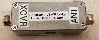
| Figure 1: The completed absorptive VSWR bridge. |
A bit about the Wheatstone bridge:
The Wheatsone bridge is one of the oldest-known types of electrical circuits, first having been originated around 1833 - but popularized about a decade later by Mr. Wheatstone itself. Used for detecting electrical balance between the halves of the circuit, it is useful for indirectly measuring all three components represented by Ohm's law - resistance, current and voltage.
 |
| Figure 2: Wheatstone bridge (Wikipedia) |
Figure 2 shows the classic implementation of a Wheatstone bridge. In this circuit, balance of the two legs (R1/R2 and R3/Rx) results in zero voltage across the center, represented by "Vg" which can only occur when the ratio between R1 and R2 is the same as the ratio between R3 and Rx. For operation, that actual values of these resistors is not particularly important as long as the ratios are preserved.
If you think of this is a pair of voltage dividers (R1/R2 and R3/Rx) its operation makes sense - particularly if you consider the simplest case where all four values are equal. In this case, the voltage between the negative lead (point "C") and point "D" and points "C" and "B" will be half that of the battery voltage - which means the voltage between points "D" and "B" will be zero since they must be at the same voltage.
Putting it in an RF circuit:
Useful at DC, there's no reason why it couldn't be used at AC - or RF - as well. What, for example, would happen if we made R1, R2, and R3 the same value (let's say, 50 ohms), instead of using a battery, substituted a transmitter - and for the "unknown" value (Rx) connected our antenna?
 |
| Figure 3: The bridge, used in an antenna circuit. |
This describes a typical RF bridge - known when placed between the transmitter and antenna as the "Tayloe" bridge, the simplified diagram of which being represented in Figure 3.
Clearly, if we used, as a stand-in for our antenna, a 50 ohm load, the RF Sensor will detect nothing at all as the bridge would be balanced, so it would make sense that a perfectly-matched 50 ohm antenna would be indistinguishable from a 50 ohm load. If the "antenna" were open or shorted, voltage would appear across the RF sensor and be detected - so you would be correct in presuming that this circuit could be used to tell when the antenna itself is matched. Further extending this idea, if your "Unknown antenna" were to include an antenna tuner, looking for the output of the RF sensor to go to zero would indicate that the antenna itself was properly matched.
At this point it's worth noting that this simple circuit cannot directly indicate the magnitude of mismatch (e.g. VSWR - but it can tell you when the antenna is matched: It is possible to do this with additional circuitry (as is done with many antenna analyzers) but for this simplest case, all we really care about is finding when our antenna is matched. (A somewhat similar circuit to that depicted in Figure 3 has been at the heart of many antenna analyzers for decades.)
Antenna match indication and radio protection:
An examination of the circuit of Figure 3 also reveals another interesting property of this circuit used in this manner: The transmitter itself can never see an infinite VSWR. For example, if the antenna is very low resistance, we will present about 33 ohms to the transmitter (e.g. the two 50 ohm resistors on the left side will be in parallel with the 50 ohm resistor on the right side) - which represents a VSWR of about 1.5:1. If you were to forget to connect an antenna at all, we end up with only the two resistors on the left being in series (100 ohms) so our worst-case VSWR would, in theory, be 2:1.
In context, any modern, well-designed transmitter will be able to tolerate even a 2.5:1 VSWR (probably higher) so this means that no matter what happens on the "antenna" side, the rig will never see a really high VSWR.
If modern rigs are supposed to have built-in VSWR protection, why does this matter?
One of the first places that the implementation of the "Tayloe" bridge was popularized was in the QRP (low power) community where transmitters have traditionally been very simple and lightweight - but that also means that they may lack any sophisticated protection circuit. Building a simple circuit like this into a small antenna tuner handily solves three problems: Tuning the antenna, being able to tell when the antenna is matched, and protecting the transmitter from high VSWR during the tuning process.
Even in a more modern radio with SWR protection there is good reason to do this. While one is supposed to turn down the transmitter's power when tuning an antenna, if you have an external, wide-range tuner and are quickly setting things up in the field, it would be easy to forget to do so. The way that most modern transmitter's SWR protection circuits work is by detecting the reflected power, and when it exceeds a certain value, it reduced the output power - but this measurement is not instantaneous: By the time you detect excess reflected power, the transmitter has already been exposed - if only for a fraction of a second - to a high VSWR, and it may be that that brief instant was enough to damage an output transistor.
In the "old" days of manual antenna tuners with variable capacitors and roller inductors, this may have not been as big a deal: In this case, the VSWR seen by the transmitter might not be able to change too quickly (assuming that the inductor and capacitors didn't have intermittent connections) but consider a modern, automatic antenna tuner full of relays: Each time the internal tuner configuration is changed to determine the match, these "hot-switched" relays will inevitably "glitch" the VSWR seen by the radio, and with modern tuners, this can occur many times a second - far faster than the internal VSWR protection can occur meaning that it can go from being low, with the transmitter at high power, to suddenly high VSWR before the power can be reduced, something that is potentially damaging to a radio's final amplifier.
While this may seem to be an unlikely situation, it's one that I have personally experienced in a moment of carelessness - and it put an abrupt end to the remote operation using that radio - but fortunately, another rig was at hand.
A high-power Tayloe bridge:
It can be argued that these days, the world is lousy with Tayloe bridges as they are seemingly found everywhere - particularly in the QRP world, but there are fewer of them that are intended to be used with a typical 100 watt mobile radio - but one such example may be seen below:
 |
| Figure 4: As-built high-power Tayloe bridge with a more sensible
bypass switch arrangement! This diagram was updated to include a
second LED to visually indicate extreme mismatches and provide another
clue as to when one is approaching a match - see figure 7 at the bottom of the article. |
Figure 4 shows a variation of the circuit in Figure 2, but it includes two other features: An RF detector, in the form of an LED (with RF rectifier) and a "bypass" switch, so that it would not need to be manually removed from the coax cable connection from the radio.
In this case, the 50 ohm resistors are thick-film, 50 watt units (about $3 each) which means that between the three of them, they are capable of handling the full power of the radio for at least a brief period. Suitable resistors may be found at the usual suppliers (Digi-Key, Mouser Electronics) and the devices that I used were Johanson P/N RHXH2Q050R0F4 (A link to the Mouser Electronics page is here) - but there is nothing special about these particular devices: Any 50-100 watt, TO-220 package, 50 ohm thick-film resistor with a tolerance of 5% or better could have been used, provided that its tab is insulated from the internal resistor itself (most are).
How it works:
Knowing the general theory behind the Wheatstone bridge, the main point of interest is the indicator, which is, in this case, an LED circuit placed across the middle of the bridge in lieu of the meter shown in Figure 1. Because RF is present across these two points - and because neither side of this indicator is ground-referenced, this circuit must "float" with respect to ground.
If we presume that there will be 25 volts across the circuit - which would be in the ballpark of 25 watts into a 2:1 VSWR - we see that the current through 2k could not exceed 25 mA - a reasonable current to light an LED. To rectify it, a 1N4148 diode - which is both cheap and suitably fast to rectify RF (a garden-variety 1N4000 series diodes is not recommended) along with a capacitor across the LED. An extra 2k LED is present to reduce the magnitude of the reverse voltage across the diode: Probably not necessary, bit I used it, anyway. QRP versions of this circuit often include a transformer to step up the low RF voltage to a level that is high enough to reliably drive the LED, but with 5-10 watts, minimum, this is simply not an issue.
Because the voltage across the bridge goes to zero when the source and load impedance are matched (or the switch is set to "bypass" mode) there is no need to switch the detector out of circuit but note that the LED and associated components are "hot" at RF when in "Measure" position which means that you should keep the leads for this circuit quite short and avoid the temptation to run long wires from one end of a large enclosure (like an antenna tuner) to the other as excess stray reactance can affect the operation of the circuit.
Note: See the end of this article for an updated/modified version with a second LED .
A more sensible bypass switch configuration:
While there are many examples of this sort of circuit - all of them with DPDT switches to bypass the circuit - every one that I saw wired the switch in such a way that if one were to be inadvertently transmitting while the switch was operated, there would be a brief instant when the transmitter was disconnected (presuming that the switch itself is a typical "break-before-make" - and almost all of them are!) that could expose the transmitter to a brief high VSWR transient. In Figure 3, this switch is wired differently:
- When in "Bypass" mode, the "top" 50 ohm resistor is shorted out and the "ground" side of the circuit is lifted.
- When in "Measure" mode, the switch across the "top" 50 ohm resistor is un-bridged and the bottom side of the circuit is grounded.
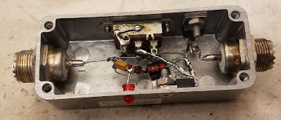 |
| Figure 5: Inside the bridge, before the 2nd LED was added |
An as-built example:
I built my circuit into a small die-cast aluminum box as shown in Figure 5. Inside the box, the 50 ohm resistors are bolted to the box itself using countersunk screws and heat-sink paste for thermal transfer. To accommodate the small size of the box, single-hole UHF connectors were used and the circuit itself was point-to-point wired within the box.
For the "bypass" switch (see Figure 6) I rescued a 120/240 volt DPDT switch from an old PC power supply, choosing it because it has a flat profile with a recessed handle with a slot: By filing a bevel around the square hole (which, itself was produced using the "drill-then-file" method) one may use a fingernail to switch the position. I chose the "flush handle" type of switch to reduce the probability of it accidentally being switched, but also to prevent the switch itself from being broken when it inevitably ends at the bottom of a box of other gear.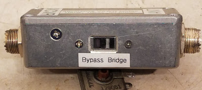 | |
| Figure 6: The "switch" side of the bridge. |
As on might posit from the description, the operation of this bridge is as follows:
- Place this device between the radio and the external tuner.
- Turn the power of the radio down to 10-15 watts and select FM mode. You may also use AM as that should be limited to 20-25 watts of carrier when no audio is present.
- Disable the radio's built-in tuner, if it has one.
- If using a manual tuner, do an initial "rough" tuning to peak the receive noise, if possible.
- Switch the unit to "Bridge" (e.g. "Measure") mode.
- Key the transmitter.
- If you are using an automatic tuner, start its auto-tune cycle. There should be enough power coming through the bridge for it to operate (most will work reliably down to at about 5 watts - which means that you'll need the 10-15 watts from the radio for this.)
- If you are using a manual tuner, look at both its SWR meter (if it has one) and the LED brightness and adjust for minimum brightness/reflected power. A perfect match will result in the LED being completely extinguished.
- After tuning is complete, switch to "Bypass" mode and commence normal operation.
 | |
| Figure 7: The "enhanced" version with TWO LEDs. |
 |
| Figure 8: It has two LEDs now! |
Thanks for the patient development of the explanation of the red LED in my QRP Z-Match tuner. I now understand how the tune position protects my rig while still allowing the tuner to see the antenna.
ReplyDelete