Saturday, December 7, 2019

Automatically re-connecting low-voltage cut-outs for 12 and 24 volt lead acid battery systems

In a previous post I described a simple circuit that provided a low-voltage cut-out that could be used in a battery-operated system - see the article "A latching low-voltage disconnect for 12 volt lead-acid and lithium batteries".

That circuit - intended mostly for lithium-based batteries - required manual intervention to "reset" the device, intended for those situations where you wanted to provide manual intervention in resetting the circuit to prevent causing harm to the battery - and maybe the gear connected to it.

Figure 1:
The completed 24 volt low-voltage cut-out.  R5, the cut-off voltage
adjustment, is the blue 10-turn potentiometer near the middle and
R8 is the black, single-turn potentiometer near the top, to the left
of Q1 and its heat sink.  U1 is the lower transistor-looking device
near the left side of the board.
This device was installed in an outdoor enclosure that houses a relay
point to bridge a wireless Internet connection over a hill that has
a 24 volt back-up battery system.  In the event of an extended
power outage, this device prevents damage to the batteries,
particularly in the winter where this device will
prevent the batteries from being damaged by freezing.
The small heat sink is adequate for this FET and an operating
current of 5 amps.
Click on the image for a larger version.
This circuit is different from that described in the link above, intended for lead-acid battery based systems where an automatic reconnect of the battery is required when the battery voltage rises above a threshold voltage after application of charge current.  An example of where this would be useful is a system in which the battery is charged by a main-powered DC supply that is used to keep the battery charged where the battery will power the load in the event of a power failure.

Why would we worry about this?

Related to this, let's briefly talk about maximizing longevity of lead-acid batteries:
  • For best longevity, the shallower the discharge, the better.  A classic example of this is a solar-powered system where there is a daily discharge.  If the battery were sized too small such that it was discharged from "full" to 30% every day, it might last only a year or so at best, but by increasing the battery size such that it was only discharged to 75% worst-case, the cycle depth would be much shallower and the battery would last much longer.  This assumes, of course, that there is enough charging capacity to do this, which can be an issue for a solar charge system in the winter and/or periods of weather where there is little direct sun.
  • Lead-acid batteries can handle being run completely down - as long as you don't keep them in that state for very long (a few days at most - as little time as possible) and don't do it very often - and the more charge you can leave on them at the deepest point of discharge, the better.  In other words, if you run an otherwise healthy lead acid battery completely dead and immediately recharge it, little immediate damage is likely to have been done other than taking a bit of life off it farther down the road as most lead-acid batteries can only handle a few hundred of such cycles before they are significantly and permanently degraded.  (The previous statement applies only to "Deep Cycle" lead-acid batteries:  Automotive "starting" batteries do not fall into this category - They can be permanently damaged by as few as dozen or two "complete" discharge cycles in some cases.)
  • In cold-weather environments, while the degradation (primarily sulfation) caused by the battery being dead for extended periods is dramatically slowed, extremely deep discharge also reduces the specific gravity, raising the electrolyte's freezing point and increasing the possibility of the battery being damaged/destroyed at very low temperatures if it does get cold enough to freeze the electrolyte.  Preventing too-deep a discharge by disconnecting the load while there is still some capacity left can reduce the probability of this happening.  (This can happen with both flooded cell and AGM batteries.)
  • Important:  A general rule of thumb is that above approximately 70F (approx 20C) for every 10F (approx. 5.5c) increase in temperature, the expected lifetime of a lead-acid battery is approximately halved.  Carefully consider this if the battery is to be in a location that might get warm/hot.
For several of the reasons mentioned above, a low-voltage disconnect circuit is essential in systems where there is the distinct possibility that the battery could be completely discharged - both to prevent the loss of battery capacity due to over-discharge (e.g. sulfation if the battery is left "flat" for a long time) as well as preventing freezing of the electrolyte when the battery is deeply discharged where/when that is a concern.

A simple low-voltage cut-off circuit:

While there are many ways to build such a circuit, the circuit below - designed for a 24 volt battery system (values are included for use with a 12 volt battery) - demonstrates a simple, yet flexible device.

Figure 2:
A low-voltage battery disconnect, designed for 24 volts.  It has a useful adjustment range of between 22 and 28 volts.
For 12 volts:  R2=4.7k, R4=62k, R7=47k, R11=47k, R12, R13, R14=10k.
 Components LED2 and R14 are optional, used to indicate that the circuit has disconnected the battery from the load.  (Errata:  LED2 is shown connected backwards.)

Not shown is appropriate fusing on the battery side of the circuit to protect against short circuits and/or catastrophic component failures.
Click on the image for a larger version.
This circuit, somewhat similar to that described in the other article linked above, works as follows:

The battery voltage is measured using R4, R5 and R6 which form an adjustable divider to take the battery voltage down to the 2.5 volt comparison voltage required by U1, a TL431 "programmable" zener diode.  When the voltage at the wiper of R5 goes above 2.5 volts, U1 will conduct.

When U1 conducts it pulls down the voltage at the base of Q1 via R3 causing it to turn on.  This voltage, via R12, is fed to the gate of Q1 - an N-channel power MOSFET in the negative battery lead. In this way, as long as the voltage is above the threshold set by R5, Q1 is turned on, connecting the load to the battery.  While U1 is turned on and pulling the voltage at the bottom end of R3 close to ground, the voltage at the gate of Q3 is low, keeping it turned off.

If the divided battery voltage drops below the low-voltage cut-out threshold, U1 turns off and its cathode is pulled high by R2 with resistor R1 being used to allow Q2's gate to go high and turn it off.  When Q2 is turned off, the gate voltage on Q1 goes away, being pulled to its source potential by R11.

At this same time, the rise in voltage at U1's cathode also causes Q3 to be turned on and the voltage at the junction between R4 and R5 is pulled slightly down, requiring a higher battery voltage to turn U1 back on than was required for it to be turned off, thus providing a bit of hysteresis.  It is by adjusting R5 that the amount of hysteresis (e.g. the amount by which the turn-on voltage must be higher than the cut-off voltage) may be set.

There are some "extra" components included to make the circuit more robust:
  • C1, across the reference pin of U1, reduces this circuit's susceptibility to being triggered by power glitches (e.g. lightning) and stray RF energy.  If the circuit tends to trip out when a load is activated (e.g. voltage "dip" caused by battery/lead resistance)  this capacitor can be increased in value to slow U1's response - up to several microfarads.
  • Capacitors C2 and C3 are across their respective FET's gates to provide RF energy protection as well as to smooth transients that might cause false triggering or damage.
  • ZD1 is placed between Q1's source and gate to protect it against excess voltage that would damage the device - possibly caused by transients.  The maximum gate-source voltage rating of a typical power FET (Q1) is around 20 volts, so this is a required component for the 24 volt version.
  • Finally, C4 is placed across the drain and source leads of Q1 to provide both resilience to stray RF energy as well as to suppress transients that might appear across it when the power is off.
 
Also included in the circuit is the "power on" indicator consisting of LED1 and R13 which provides an indication that voltage is present between the "Load +" and "Load -" terminals.  The optional circuit containing LED2/R14 shows when Q1 is turned off (e.g the load is disconnected) by detecting when there is a voltage drop across it.  (Note:  LED2 was accidentally drawn "backwards" in Figure 2.)

Comments:
  • Important:  To simplify the design, it is the "Batt -" lead that is switched to disconnect the load.  What this means is that the negative battery lead must not be connected anywhere else or the battery disconnect will not work properly.  It is possible to design the circuit to use a P-channel FET in the positive lead, but high-current N-channel devices are more plentiful and less expensive.  Instead of a power FET, a slight modification will allow a relay to be used, instead - but at much higher quiescent current owing to the required current for the coil.
  • LED1 and LED2 may indicate correctly only when there is a load connected across the "Load +" and "Load -" terminals.
  • Even when the load is disconnected this circuit will draw several milliamps of current due to the quiescent load of U1, its voltage divider and LED2, the "Battery Disconnected" indicator.  Keep this in mind if you are going to use it in an application where there is a reasonable probability that battery charging may be unavailable for very long periods of time.
  • The current capability of this circuit is limited by the current-handling capability of Q1, the power FET, and the amount of heat-sinking attached to it.  When choosing a power FET, not only should the current rating be considered, but also the specified "on" resistance.  For example, if a 50 amp FET is used and it has an ON resistance of 0.01 ohms, at 20 amps it will dissipate at least (20 * 20 * 0.01 = )  4 watts and will drop (20 * 0.01 = ) 0.2 volts.  The heat sink shown in Figure 1 is capable of dissipating that much power under all but the hottest ambient temperature.
Comment about Q1, the main power FET:

The power FET is not specified, as practically any appropriate N-Channel power FET will work - and here are a few selection guidelines:
  • Pick a device with a current rating of at least 3 times the maximum that you expect to draw.  100-150 amp devices are fairly inexpensive, so don't be afraid to pick a far "heftier" device than you might otherwise select.  Note that while a particular FET may have a "150 amp" rating, if there is a short circuit downstream, it is possible that connections inside the FET itself may act as a quicker-acting fuse than an actual fuse intended to protect the circuit.
  • Pick a device with a voltage rating of at least 4 times the battery voltage, which would imply at least a 125 volt device for 24 (really around 28) volts and 75 volt device for 12 (really around 14) volts - and there is little penalty in going higher than that given a choice of devices with the same rated current.
  • With a properly functioning circuit, a heat sink is likely not required, but a small heat sink doesn't hurt - particularly if the circuit will be exposed to high temperatures.  While the "on" resistance of a saturated power MOSFET can be very low, it is not zero and at maximum expected current, the FET can produce a some heat.
    • Note that a FET's "on" resistance may be a fraction of an ohm, but it is not zero so some voltage will be dropped - and heat generated - by the FET.
    • Remember the formula - Power in watts = I*I*R where "I" is the current and "R" is the "on" resistance of the FET - and if power is more than 2-3 watts, consider a larger heat sink for Q1 - and after it is built, make sure Q1 isn't getting "hot" under the expected load.
The amount of current that can be handled by this cut-off-switch is essentially the limit of the chosen FET, the fusing, and the interconnection wiring.
Examples of FETs:
  •  The IRF540 is rated for 25+ amps at 100 volts and this would be an excellent device for a disconnect that was intended to handle 5-8 amps at 12 volts.  This device is inexpensive and readily available - even from surplus outlets, less than $1.50 from Electronic Goldmine.
  • The 45N20 is rated for 35 amps at 200 volts and would be a good choice for 10-12 amps and either a 12 or 24 volt disconnect - and is also available from Electronic Goldmine as the "SSP45N20".
(The Electronic Goldmine is used as an example of surplus electronic suppliers.  These parts are readily available from suppliers such as Digi-Key, Mouser, etc.  Always buy parts like this from reputable suppliers as counterfeit power devices are quite common.)

Adjustment:

Important:  Verify that the circuit works and is properly adjusted before placing it into service!

The procedure is as follows:
  • Set R8 for maximum resistance. 
  • Connect "Batt +" and "Batt -" to an adjustable DC power supply that is capable of providing between 20 and 30 volts.
  • Connect a known-accurate voltmeter to the DC power supply to measure the "Battery" voltage.
  • Connect a load to the output terminals ("Load +" and "Load -").  A small lamp of the correct voltage or resistor (1k at 1 watt or more) will do. 
  • Increase the voltage to 30 volts:  The load will turn on. (15 volts for the 12 volt version.) 
  • Decrease the voltage slowly:  The load will turn off below a certain voltage.
  • Increase voltage again to turn the load back on and then adjust R5 so that the load turns off at the desired voltage  The lowest cut-off voltage that is suggested is 1.92 volts/cell for a state-of-charge of 20-25% at "room temperature", which translates to:
    • For a 12 volt lead acid battery, 11.5 volts
    • For a 24 volt lead acid battery, 23.0 volts
    • Note:  At very low temperatures, the output voltage of a lead acid battery will drop given a constant charge level.  This means that in the case of the 12 volt battery that is cold (32F, 0C) a 11.5 volt cut-off would imply that the actual charge level of a battery would be higher than the 20-25% level indicated by this same voltage of the battery were at room temperature.
  • This concludes the adjustment of the cut-off voltage.  Adjusting R8 should not affect the cut-off voltage.
  • Set the power supply voltage below the cut-off voltage and slowly increase it until the load turns back on, noting the voltage at which that happens.
  • Adjust R8 so that the cut-in voltage is adjusted as desired.  The cut-in voltage is much less critical, but should be well above the cut-out voltage.
    • A typical cut-in voltage for a 12 volt lead-acid battery is 13 volts, or 2.17 volts/cell, but it may be set lower - to 12.5 volts (2.083 volts/cell) if quicker power restoration is required in a system that has limited charge capacity. 
    • A typical cut-in voltage for a 24 volt lead-acid battery is 26 volts, or 2.17 volts/cell, but it may be set lower - to 25 volts (2.083 volts/cell) if quicker power restoration is required in a system that has limited charge capacity. 
    • Note:  A higher cut-in voltage may delay restoration of the output load, but it will allow the battery to charge more before the load is restored.  An example where this may be important is in a solar-powered system where a low output from the PV array may be sufficient to slowly charge the battery, but may not be able to sustain the load:  This can happen in the morning, when the panels are covered with snow, and/or on very dark and cloudy days.
  •  Re-check the cut-off and cut-in voltages:  When adjustment is needed, remember to set the cut-off voltage first and then the cut-in voltage.

Comment:
This device could be used for similar-voltage Lithium-based batteries with appropriate adjustment of the cut-in and cut-off voltages.  Note that any Lithium-based battery system should already have a "protection" circuit that protects against over and under voltage.  Particularly with LiFeO4 batteries, a circuit to equalize the voltage across the cells should be used.
* * *

This page stolen from ka7oei.blogspot.com

[End]


Sunday, November 17, 2019

Homebrew construction of 2 and 4 port splitters/combiners for the LF-MF-HF(30 kHz-30 MHz) frequency range.

Note:

This is a follow-up of a previous article, "Characterizing the Mini-Circuits ZFSC-4-3, ZFDC-20-3, ZFSC-4-1-BNC+ and ZFSC-2-1+ well below their designed frequency range" - link.

Comment:
All of the devices described here could also be used to combine signals from multiple sources.  Unless the signals being combined are "phase coherent" (e.g. from the same signal source) the insertion loss will be the same as that in splitter operation.

"Rolling your own" splitter for LF through HF (<30kHz-30MHz):

Unless you get the Mini-Circuits devices for cheap at a swap meet or via a surplus outlet, their cost may be a bit prohibitive for casual use in the shack.  How about making your own splitter that will work over the 30 kHz-30 MHz range?

Why would one want this?  There are a number of modern Web-Based SDR receivers that cover from (literally!) audio through 30 MHz - and in my case, I have a number of KiwiSDR receivers - link that are connected to an antenna system that is capable of intercepting signals over this range.  If one has several such receivers, it can be a challenge to find a splitter that works well over this range - particularly the low end - as described in the article linked above.

Figure 1:
A two-transformer splitter/combiner.  L1 transforms the impedance at
J1 to half that value and L2 splits the signal itself.  R is twice the system impedance
- 100 ohms in a 50 ohm system.  The tap on L1 is at 0.707 times of the total
number of turns:  A tap at 7 of 10 total turns is "close enough" while C is a high-
frequency compensating capacitor.  L2 is a bifilar-wound transformer with the
two sets of windings connected in series at the common point.
Click on the image for a larger version.
To do this, ferrite - rather than iron-powder - cores would be used, the most common types using mix 31, 43, 61, 73 and 75 - and the most useful of the lot for the low-frequency end are types 73 and 75.  Not having a complete assortment of the ferrite types on hand, I used what I had and the use of a binocular core with mix 43 and a ferrite with mix 75 is discussed here.

Two-transformer splitter/combiner:

A common splitter topology consists of two cores:  One to transform the impedance to half that of the characteristic system impedance and a second to split the signal two ways as depicted in Figure 1.  The inductance of L1 and L2 should be high enough to present a reactance of 3-10 times the system impedance at the lowest frequency.

Figure 2:
Measured insertion loss of a transformer using two BN43-202 cores wound
with 30 AWG wire:  10 turns, tapped at 7 turns for L1 and 10 bifilar turns
for L2.  R = 100 ohms and C = 62pF.
The required number of turns to achieve the desired low-frequency response
increases the stray capacitance, undesirably increasing loss at the
high-frequency end of the HF spectrum.
Click on the image for a larger version.
Figure 2 shows a tested version of this transformer, the details noted in the caption.  According to this diagram the insertion loss is a nominal 3-ish dB from 50 kHz to 1 MHz, dropping down to about 5 dB loss between 20 kHz and 10 MHz and nearly 6dB at 30 MHz.  Capacitor "C" was made variable, adjusted for lowest loss, improving the highest end by a bit over 1dB, and its value measured.

For LF and HF use, this splitter is just "OK" - the loss being an extra 3dB at the high end of the spectrum:  If preceded with amplification, this loss may be tolerable - but note that even the nominal 3dB loss of a 2-way splitter should be of concern at the higher HF bands as signals - and the natural noise floor - can be quite weak and additional loss can drop the receiver's noise floor below that, potentially causing the loss of reception of weaker signals.

Much of the high-frequency loss is due to the inter-winding capacitance.  Experimentally, versions were constructed using wire with PTFE ("Teflon") insulation and comparing it with another with the same number of turns of the 30 AWG enamel and the losses for the PTFE wire version were 1.5-2dB lower - but fewer turns could be passed through the core and low-frequency response suffered.

Figure 3:
In this form, the primary (connected to J1) has 1.414 times as many turns
as each of the two identical secondary windings.  The value of R is half that
of the characteristic system impedance, or 25 ohms for a 50 ohm system:
Parallel 51 ohm resistors were used for a nominal 25.5 ohms.
Typical turns values are 10/7 turns, 14/10 turns and 20/14 turns for the
primary and bifilar secondary, respectively.  For the center-tap, the windings
of the secondary are connected as if they were in series.
Click on the image for a larger version.
If a higher-permeability material (like 73 or 75 mix) were used for the core rather than 43, fewer turns could have been used to maintain the inductance and low-frequency response and it is likely that the high-frequency loss would be reduced.

Single-transformer splitter-combiner:

Another common splitter/combiner is the form depicted in Figure 3, using a single core - and potentially this can reduce loss compared with a device with two cores.

In this system the primary should consists of 1.414 times (e.g. the square root of two) as many turns as each of the secondary windings.

Figure 4:
The insertion loss of the described two-way splitter using 24 AWG wire on
an FT50-75 core:  It is well below 4dB over the range of 10 kHz to 60 MHz.
Click on the image for a larger version.

Both a binocular and toroidal core were tried and better results were obtained with the FT50-75 core than the available BN43-202 binocular core - both because the higher permeability improved the low-end response and larger wire could be used for the toroid:  Capacitance was reduced on the toroid because the turns could be spread out rather than being tightly overlaid as the case of the binocular core, and high-end losses were further-reduced by laying the turns of the secondary next to each other rather than the higher capacitance resulting from the two conductors being twisted as is commonly done with Bifilar windings.

The results of this work are visible in Figure 4.  For this transformer, two parallel secondary "bifilar" windings consisting of 14 turns each were carefully and neatly laid down using 24 AWG enamel wire with 20 turns of 24 AWG over the top.  As can be seen, the results are excellent:  The insertion loss is below 3.6dB from 10 kHz to 60 MHz and the overlaid Smith chart shows the VSWR to be pretty well-behaved, never exceeding 1.5:1 over this range.

Figure 5:
The port-to-port isolation is quite good over the range of 100 kHz to
30 MHz.  The peculiarly-flat isolation limit of the bottom "trough"
of the graph is a result of the value of "R" not being exactly 1/2 of the
impedance value of the system used for testing:  If R is made variable,
higher isolation may be obtained in the middle of the range - but the
difference between that and the fixed resistors used was only an
ohm or two.  In practice, high values of isolation can be obtained only
if the source and load impedances are purely resistive, but since
practical antennas, amplifiers, receivers and filters will not be perfect
sources and loads, such high isolation cannot be achieved in practice.
Click on the image for a larger version.
Additional tests were run to determine the port-to-port isolation of this splitter - the results being visible in Figure 5.  Over the range of 100 kHz through 60 MHz, the isolation exceeds 15dB, exceeding 25dB from abut 100 kHz through 30 MHz.  During testing, the same device had been constructed using smaller 30 AWG wire and the results were worse above 10 MHz (by 2dB at 30 MHz) - likely a result of the skin effect losses of this smaller wire.

A four-way splitter:

I happened to have a need to take signals over a wide frequency range and split it four ways - specifically, to several KiwiSDR receivers, stand-alone web-based receivers capable of reception over the 5kHz-30MHz range - so I decided to construct a splitter using the configuration described above.  To do this, I would need three splitters:  A pair of splitters to feed the four outputs and one more splitter to feed the aforementioned two splitters.  This splitter is depicted schematically in Figure 6:
Figure 6:
For a 50 ohm system, resistors "R" are 25.5 ohms (two 51 ohm resistors
in parallel) and capacitors "C" are 47pF NPO/C0G types used to "flatten"
the response to 30 MHz.
The as-built splitter uses FT50-75 cores wound with 24 AWG, the dual
secondary windings consisting of 14 turns and the primary with 20 turns.
The dual secondaries are laid parallel rather than twisted to minimize stray
capacitance.  The center-tap is connected as if the two secondary windings
were placed in in series.
Click on the image for a larger version

This splitter consists of three of the two-way splitters connected as described:  FT50-75 cores wound with 14 turns, each of two parallel 24 AWG conductors for the secondary overlaid with 20 turns of 24 AWG for the primary.  During testing it was observed that the addition of capacitors "C" slightly reduced (by nearly 1 dB) the insertion loss at 30 MHz at the expense of increased loss (about 2dB) at 60 MHz - but because the target high-end limit was 30 MHz, this was considered to be acceptable.

The end result was an insertion loss (see Figure 7) of less than 7 dB from 20 kHz through 30 MHz, rising to 8 dB and 9.3 dB at 10 kHz and 60 MHz, respectively, being under 6.3dB between 50 kHz and 10 MHz.  In testing port-to-port isolation, the worst case results were those obtained from the same transformer (e.g. T2 or T3) and this value was at least 15dB from 50 kHz to 30 MHz.

Figure 7:
This shows the typical insertion loss of the as-built four-way splitter
depicted schematically in Figure 17.  The insertion loss is less than 7 dB
from at least 20 kHz through 30 MHz with the VSWR being 1.5:1
or less over that same range.
Click on the image for a larger version.
This four-way splitter was built into a small die-case box for mechanical rigidity and electrical shielding.  Inside the box, pieces of plastic tape were affixed to the bottom and the lid to eliminate the possibility of inadvertent shorting of connections to the case:  Details of the mechanical construction may be see in Figure 8.

To reiterate:  It was determined that with the number of turns required to obtain good response into the LF range (e.g. below 30 kHz) that the use of twisted bifilar windings was NOT indicated:  Doing so resulted in excess loss (3-6dB) by the time one got to 30 MHz.  As indicated, the use of thicker insulation (e.g. PTFE versus enamel) reduced this loss somewhat, but using the smallest wire on hand with the only available 75 mix toroid, too few turns could be wound to afford the needed inductance for the desired low frequency respons:  The best-results with the materials on-hand were obtained by simply laying the "bifilar" windings parallel to each other.  In this case, 24 AWG enamel wire was used, a compromise between lower skin-effect losses and the ability to fit the required number of turns on the FT-50 core.

Comment:  There are other splitter topologies available that have their own sets of advantages and disadvanges.  While some of these may be discussed in (a) future article(s), they are beyond the scope of this article - which is the construction of a very simple, straightforward device that is suitable for the task at hand.

Conclusion:

If one needs a very wide-range splitter for broadband receivers that cover from LF through HF - such as some modern "Direct Sampling" SDRs (e.g. the KiwiSDR) there are some commercially-available devices that may be found that will work well - if you can find them surplus, or are willing to pay for them.  If you are willing, a perfectly suitable device may be constructed inexpensive using a minimal complement of components.

Figure 8: 
The as-built 4-way splitter. capable of useful operation from below 20 kHz to above 30 MHz.
As described in the text, the cores are FT50-75 wound with 24 AWG wire, wired "dead bug"
inside a small die-cast aluminum box.  The resistors "R" and compensating capacitors "C"
may be easily seen.  The bottom of the box and the lid (not visible) are insulated with a piece
of plastic tape - this this case, 1" (25mm) wide PET (Polyester) tape.  If I'd had some on hand,
I would have wound the transformers on slightly larger toroids to spread out the windings a bit.
Click on the image for a larger version.
* * *

This is a follow-up of a previous article, "Characterizing the Mini-Circuits ZFSC-4-3, ZFDC-20-3, ZFSC-4-1-BNC+ and ZFSC-2-1+ well below their designed frequency range" - link.


Stolen from ka7oei.blogspot.com


[End]

Wednesday, November 6, 2019

Characterizing the Mini-Circuits ZFSC-4-3, ZFDC-20-3, ZFSC-4-1-BNC+ and ZFSC-2-1+ well below their designed frequency range

Figure 1:
The collection of devices to be tested - plus a few 50 ohm terminators.
Click on the image for a larger version.
Note: 

There is a follow-up article, "Homebrew Construction of 2 and 4 port splitter-combiners for the LF/MF/HF frequency range" link.


Rummaging through a box of RF stuff I ran across several multi-port devices made by Mini-
Circuits Labs that I'd picked up over the years - typically at amateur radio swap meets.

The "official" specs of these devices are easy to find (at least for the newer "plus" versions) but what if, like me, one was interested in using them at frequencies below their official design specs - such as the lower amateur bands, including 80, 160, 630 and 2200 meters?  How much "extra" design margin was built into these device?

Wielding my DG8SAQ Vector Network Analyzer, I decided to find out.  For these measurements I limited the range to between 10 kHz and 60 MHz.  I also built several homebrew versions to see if I could, for little cost, come up with suitable versions of my own - and these are described in the follow-up article linked at the top of this page.

Comment:
All of the devices described here could also be used to combine signals from multiple sources.  Unless the signals being combined are "phase coherent" (e.g. from the same signal source) the insertion loss will be the same as that in splitter operation.  They will be referred to only as "splitters" in this article to minimize clutter.

Figure 2:
 Insertion loss of the ZFSC-4-3 from 10 kHz to 60 MHz.
Even though the "official" low-frequency specification is 10 MHz,
it should be quite usable on 160 meters (down to at least 1.8 MHz).
Click on the image for a larger version.
ZFSC-4-3 four-way splitter:

This device, equipped with BNC connectors, has an "official" frequency range of 10-300 MHz (the currently-offered "plus" version has the same ratings), splits the signal 4 ways with a theoretical insertion loss of 6 dB, but practically speaking, the actual loss is rated as being closer to 6.4 dB over the lower end of the design range.  Although this device - and others below - are billed as a splitters, they may be used to combine disparate signals from multiple sources onto a single line with the same amount of insertion loss.

Figure 2 shows the measured insertion loss over the range of 10 kHz to 60 MHz.

Figure 3:
 Isolation of the ZFSC-4-3 from 10 kHz to 60 MHz between ports 1 and 2.
Click on the image for a larger version.
This shows us that down to about 1.8 MHz (160 meters) that the insertion loss (blue trace) is only slightly (0.15dB) higher than the rated specs - and the Smith chart (red trace) is also reasonably well-behaved.  The next marker to the left (#3) is placed at 100 kHz and we see that the insertion loss is closer to 9 dB and that the impedance has dropped to around 12 ohms - getting worse at 20 and 10 kHz where the losses are 20dB or more and the measured impedance is only a few ohms.

What this tells us is that this device is likely to be useful down to about 500 kHz, below which point the insertion loss and impedance mismatch start to become significant - likely due to the fact that the intrinsic impedance of the ferrite devices within the splitter has dropped too low at these frequencies to remain "transparent".

Figure 4:
 Isolation of the ZFSC-4-3 from 10 kHz to 60 MHz between ports 1 and 3.
Click on the image for a larger version.
Figure 3 shows the port-to-port isolation between ports 1 and 2 and the scene is similar:  The insertion loss curve is pretty flat to about 500 kHz where it starts to vary and much below 100 kHz, the isolation seems to increase, but this correlates to the insertion losses.

Figure 4 shows the port-to-port isolation between ports 1 and 3.  This is different from that in Figure 3 because a 4-way splitter actually consists of three two-way splitters:  One to split two ways, and this path is then split two more ways with ports 1 and 2 on one splitter and 3 and 4 on another - and cross-coupling to the "other" splitter is apparently not as good at frequencies below the design.

It is worth noting that all of the above measurements are contingent on all ports "seeing" a 50 ohm source and load - either from the instrument itself doing the port-to-port measurements, or by terminating the "unused" ports (e.g. those not involved in the measurements) with known-good 50 ohm loads.  It is likely that real-world devices (antennas, receivers, amplifiers, filters) connected to any splitter will not have as good a return loss (effectively, VSWR) as a load and this will affect the isolation and apparent insertion loss.

Despite what the "official" ratings say, this device would be suitable down to at least 160 meters (1.8-2.0) MHz and likely usable through the entire AM broadcast band and, possibly, the 630 meter band.
Figure 5:

Insertion loss of the ZFSC-4-1 splitter between 10 kHz and 60 MHz.
Click on the image for a larger version.

ZFSC-4-1-BNC+ four-way splitter:

This device, also equipped with BNC connectors, has an "official" frequency range of 1-1000 MHz, splits the signal 4 ways with a theoretical insertion loss of 6 dB, but practically speaking, the actual loss is rated as being closer to 6.4 dB over the lower end of the range.

Figure 6:
 Typical port-to-port isolation of the ZFSC-4-3 from 10 kHz to 60 MHz.
Click on the image for a larger version.
As Figure 5 shows, this device does a much better job at the low end of things than the ZFSC-4-3:  At 100 kHz, the insertion loss is only slightly (0.2dB) higher than at 1.8 MHz and Marker #3 at this frequency on the Smith chart shows a reasonable (approx. 1.5:1) VSWR.  By the time one gets to 20 and 10 kHz, the VSWR and insertion loss have risen - but not as bad as that of the ZFSC-4-3.

Figure 6 shows the typical port-to-port isolation (ports 1 and 2 in this case) showing that down around 100 kHz, the isolation has dropped to about 20dB - still reasonable, and comparable to the isolation to be expected at the high end (published specs, near 1 GHz) of the design frequency range.

Clearly, if one has the amateur 2200 and 630 meter bands in mind - or one is splitting signals above about 100 kHz to feed several receivers - this is a much better choice than the ZFSC-4-3.
 
Figure 7:
 Insertion loss of the ZFSC-2-1+ two-way splitter between 10 kHz
and 60 MHz.
Click on the image for a larger version.


ZFSC-2-1+ two-way splitter:

This device, equipped with BNC connectors, has an "official" frequency range of 5-500 MHz (the "plus" version has the same ratings), splits the signal 2 ways with a theoretical insertion loss of 3 dB, but practically speaking, the actual loss is rated as being closer to 3.3 dB over the lower end of the range.

Figure 8:
Port-to-port isolation of the ZFSC-2-1+ two-way splitter between 10 kHz
and 60 MHz.
Click on the image for a larger version.
Figure 7 shows the measured insertion loss and surprisingly, it looks quite good down to 100 kHz - probably due, in part, to the fact that unlike the four-way splitters, there is likely only a single ferrite device contained within to incur losses at the low end where it "runs out" of inductance on the transformer.  Down at 20 kHz the loss has gone up by about 2dB and the impedance is in the area of 20 ohms, but this device may still be fairly usable in some applications.

Figure 8 shows the port-to-port isolation and this remains above 20dB down to about 250 kHz, quickly dropping to about 14dB at 100 kHz.

What this tells us is that this device is still likely to be usable down to 100 kHz if one is able to tolerate a couple of extra dB of loss and only mediocre isolation.

Figure 9:
Insertion loss of the ZFDC-20-3 20 dB coupler from 10 kHz
to 60 MHz.  Because the "Couple" port is pulling a slight amount of
energy from the through line, a small amount of insertion loss
is to be expected.
Click on the image for a larger version.
ZFDC-20-3 20dB directional coupler:

This device is not a splitter, but rather a device designed to directionally "siphon" a small amount of signal from the "through" line - but do this only in one direction.  This device is typically used to sample (with 20dB of attenuation) a signal on a given line, or if turned around to couple in the opposite direction it can insert a signal on this same line.  A common application of this device is to measure return loss (or VSWRm using a pair of these devices), allow non-intrusive monitoring of signals on a cable and it can be used to insert a signal on that same line - say for receiver sensitivity testing - on a cable that cannot be interrupted.  Unlike a splitter, connecting/disconnecting a device on the "Couple" port will have a very small effect on the through-signal.

Figure 10:
Forward coupling loss of the ZFDC-20-3 20 dB coupler from 10 kHz
to 60 MHz.
Click on the image for a larger version.


The "official" specs of the ZFDC-20-3 indicate a frequency range of 200 kHz to 250 MHz, but one can see in Figure 9 that the insertion loss is well below 1 dB down to around 20 kHz - although the VSWR at this frequency climbs to nearly 3:1:  At 50 kHz, the insertion loss is still only about 0.25dB and the VSWR is about 1.5:1 - still within the usable range for applications that can tolerate a small amount of degradation.

On the sample port we can see on Figure 10 that the coupling is ruler-flat down to at least 100 kHz and still staying within 1dB of the nominal value down to 10 kHz - but one should keep in mind the fact that the insertion loss and the varying impedance will likely affect the through-line's signals below around 50 kHz.
Figure 11:
Reverse coupling loss of the ZFDC-20-3 20 dB coupler from 10 kHz
to 60 MHz.  Because the coupling is 20dB in the forward direction,
the attenuation values depicted in the above graph should be reduced
by that amount.  The "bump" at the extreme low end is an artifact
of the configuration of the test instrument.
Click on the image for a larger version.

Figure 11 shows the "reverse" coupling loss (e.g. "directionality").  Ideally, no signal should be detectable when the "load" is a perfect, non-reflective 50 ohms but due to imperfections in the load, device, cabling and measurement will reduce this.

This shows that the absolute directionality+coupling exceeds about 60dB (about 40dB of directivity compared to the "forward" coupling) at all frequencies below 60 MHz down to about 20 kHz:  Values below about 70dB (the "floor" between 20 kHz and 10 MHz) are representative of the limits of the test instrument and its configuration so they may actually be greater than this.  Below about 15 kHz, the "bump" is mostly due to measurement artifacts - but this still indicates that the relative directionality is at least 30dB.

These measurements indicate that this device is usable down to 50 kHz with only minor degradation, and would probably work down to 25 kHz in applications where one can tolerate a bit of extra insertion and return loss.

Final comment about the Mini-Circuits devices:

In reviewing the above tests, it would appear that these Mini-Circuits four-way splitters and the directional coupler are generally useful down to about 1/10th of their "official" low frequency rating and that down to 1/5th of their low-frequency rating, they more or less meet their "official" specs.


Follow-up article:

I have built several homebrew versions of 2 and 4 way splitters to see if I could, for little cost, come up with suitable versions of my own that will work from below the LF range through HF - and these are described in this article:  "Homebrew Construction of 2 and 4 port splitter-combiners for the LF/MF/HF frequency range" link.

* * *

Stolen from ka7oei.blogspot.com


[End]

Sunday, October 27, 2019

Shunt regulation of series-connected lead-acid batteries to equalize the voltage

There are many instances where series lead-acid batteries are connected - including:
  • 12 volt systems using two 6 volt "golf cart" batteries in series
  • 24 or 48 volts in a UPS (Uninterruptible Power Supply) consisting of several 6 or 12 volt batteries
  • A UPS system that requires much more than 48 volts - more on this, later.
One issue that arises with any system in which cells/batteries are series-connected is that the voltages across them will ultimately be unequal.  For example, in a hypothetical 24 volt system where the nominal float voltage would be about 27.1 volts it is likely that the two "12 volt" batteries will be slightly different.  If the voltages are "pretty close" (within 0.1 volt or so) there is probably on reason to be worried - but as batteries age, they will inevitably drift apart:  Before you know it you might end up with one battery at, say, 14.2 volts where it will be evolving gas (or if it is a "sealed" battery like an AGM, will start to lose electrolyte) and the other battery will then be around 12.9 volts where it will be chronically under-charged, leading to loss of system capacity.

In either case - if the battery is exposed to a consistently high or low voltage - the life of the battery will be reduced - possibly dramatically!

Figure 1:
A small pile consisting of four shunt regulators.
For convenience, these are outfitted with spring-loaded
alligator clips which allows easy installation and removal -
and eliminates the need to sandwich a ring lug on the
battery terminal and potentially increase the total series
resistance of the bank by doing so.
Click on the image for a larger version.
While there are certainly other considerations, keeping the series-connected batterys' voltages in check will certainly go a ways toward maximizing system longevity.

First, a couple words of warning:
  • Batteries are high-current devices:  Shorting can cause injury/fire, so be very careful!  Remove metal jewelry - particularly any rings, or at least cover them with tape.
  • Some types of batteries - such as "flooded-cell" lead acid - can weep a bit of sulfuric acid which can cause burns on skin and damage to clothing.
  • Some UPS systems are not isolated from the mains power and pose an electrical shock hazard:  Always assume this to be the case and take precautions (e.g. power down/disconnect.)
  • Even moderate/low voltages can cause electrical shock.
  • While this information is presented here in good faith, it is up to you to do research about its validity before implement it, taking responsibility for doing so.
  • It is up to you to research and implement safe procedures when working on this - or any - electrical gear and you are solely responsible for any damage/injury that may result.

"How do you know this?"

A quick check of manufacturers' specifications and recommendations will reveal that exposing batteries to either too-high or too-low voltage will compromise longevity, so it would seem to be "pound foolish" to ignore it happening.

As a "case study" I maintained, for several decades, several multi-battery UPS systems - the largest of which was a 300kVa system considering of two banks of forty 12 volt batteries in series that were wired in parallel (e.g. 542 volts nominal) - and with a total of eighty batteries, things are going to drift around!

Having an available BMS (Battery Monitoring System) I could easily track the voltages on the batteries - and inevitably, they started to drift apart as the batteries aged, were exposed to slightly different ambient temperatures (e.g. the ones higher up will be a degree or so warmer the the lower ones) and manufacturing variances.  Knowing full-well the implications of batteries that were drifting apart, I soon devised a simple shunt regulator, described on this page:
These "shunt" regulators are very simple:  Just several diodes (including a Zener) plus an LED that allows a selectable amount of "leakage" current so that "better" batteries (e.g. those with lower self-discharge/leakage current) aren't exposed to elevated voltages by the current of the "other" batteries.  By "tweaking" things one can balance the system so that all batteries will obtain very close to equal voltages.

Despite the fact that only the current through a few lowly LEDs (20-30 milliamps, maximum) is microscopic compared to the currents seen when the UPS was "on battery" and fully-loaded (several hundred amps) this system worked well for several years - but it required frequent adjustment as the batteries aged and their own internal leakage currents started to change:  The battery monitoring system's "live" voltage readout was an invaluable aid to allow tweaking - but this task eventually got "old".

A better shunt regulator:

The "LED+Zener+diode" arrangement has a sharper voltage-current "knee" than a simple resistor, but it was not quite "sharp enough" so I decided to upgrade to a circuit that would respond much more forcefully with increased voltage - and I chose to use the venerable TL431 "programmable Zener".  This chip is ubiquitous, appearing in almost every PC power supply ever made:  It has a temperature-stable onboard voltage reference, and it can handle up to 100 milliamps - several times the current of the original circuit.

This circuit is represented in Figure 2, below:
Figure 2:
Schematic and mechanical layout of the shunt regulators depicted in Figures 1 and 3.
Click on the image for a larger version.

This circuit is very simple in its operation:
  • U1, the TL431 will turn "on" if its reference voltage exceeds 2.5 volts, drawing current.
  • R4, the potentiometer, is adjusted so that the "reference" terminal is 2.5 volts at the desired shunt voltage.  A 10 turn potentiometer is strongly recommended as the setting of the precise voltage will be both "fiddly" and easily disturbed if a single-turn pot is used.
  • When the battery voltage is below the adjusted shunt voltage, U1 is "off", the circuit drawing a few hundred microamps.  This is likely to be less than the self-discharge current of battery itself.
  • When the battery voltage is above the adjusted shunt voltage, U1 will turn on:  The LED will illuminate - the brightness roughly proportional to the shunt current - and the bulk of the current will flow through R2.
  • Because the voltage will be high enough to activate the shunt only when the battery bank is being charged, these shunts will have negligible load when the bank is actually being used (e.g. power being drawn due to a power failure.)
  • R2 (and R1/LED1) limit the maximum current that is likely to be drawn by the circuit in the event that voltage cannot be drawn down below the threshold voltage.  This can occur during bulk charging of the battery banks and it can also occur if the sum of the threshold voltages of the individual shunt regulators is lower than the float voltage - something that could happen on a system that adjusts the float voltage with temperature (discussed below).

In practice, if we were to set the shunt voltage is set to 13.55 volts, the lead resistance connecting the circuit to the battery will result in a very sharp "knee", the circuit going from "off", drawing a few hundred microamps, to "on" and drawing nearly 100 milliamps - in just a few millivolts or 10s of millivolts  - depending on the gauge of the wire used to connect to the battery.
Figure 3:
Internal and external views of the shunt regulator.
These were built "dead bug" rather than on a circuit
board, using sleeving to insulate conductors that might
otherwise touch.  Braided silicone-fiberglass tubing
was used to insulate the large resistor as it is designed
to handle a bit of heat with the remainder of the circuit -
and the top of the braided tubing - being secured with
heat-shrinkable tubing:  The end of the LED and
potentiometer protrude from the end of the tubing.
Click on the above for a larger version.

In operation the it is suggested that the voltage threshold be adjusted to just light the LED at the ideal float voltage in order to force enough current through the charging system to assure that a small amount of current is flowing through each battery - or through the shunt regulator.  In systems that keep the batteries maintained at a constant temperature the float voltage will remain constant, but in some cases - where the batteries are in an uncontrolled climate environment - the temperature and the float voltage may vary - typically being slightly increased, by many "smart chargers", at low temperatures and decreased at high temperatures.

The information in Figure 2 suggests a voltage that works out to be about 2.26 volts/cell, which is a reasonable value for a temperature range between 10C and 35C (50F-95F).  If the charge voltage rises above this value, the shunt regulators will start to conduct - but the voltages across the battery will be equalized, provided that they were adjusted to the same voltage:  The heat produced - even though it may be just a few watts - will not be of detriment in extremely cold conditions to the performance of the battery.  At high temperatures the lower voltage being produced by the charger may not "trigger" the shunt regulator at the average voltage, but it will still keep any errant cells from straying too far in voltage from the ideal:  Because self-discharge and leakage currents of batteries increases at higher temperatures, it is arguably more important that measures to be taken to keep everything equal!

The diagram in Figure 2 shows two options -  Values for a circuit to be used with a "12 volt" battery and values for a "6 volt" battery - but the operation and set-up is identical in each case as described on the drawing itself:
  • Set the wiper of R4, the 10 turn potentiometer, the wiper is at the "ground" end.
  • Set an adjustable power supply for precisely the desired shunt voltage.  For normal "room-like" temperatures with Lead Acid batteries, 13.55 and 6.775 volts is recommended for 12 and 6 volt types, respectively.
  • Connect the unit to the power supply and adjust the potentiometer so that the LED just illuminates.   Note that even a few millivolts will make a significant difference in LED brightness which means that one adjusts several in on session and if they are "approximately" the same brightness, they will be really close to each other in threshold voltage.
  • It is strongly recommended that all units in a particular battery bank be adjusted to the same voltage.
Construction:

It was convenient, at the time, to construct these circuits in a "dead bug" manner (see Figure 3) with no circuit board:  Once the layout was determined - and thoroughly documented - it took only a few minutes to assemble each unit, trimming/bending/insulating/soldering the leads in assembly-line fashion.

The entire circuit was covered with insulating tubing - but to cover the main heat-generating component, R2, I obtained some high-temperature, silicone-fiberglass tubing.  This tubing extends beyond R2 and a small piece of "normal" heat-shrink tubing is used to cover these components and hold everything in place with the tip of the LED and the adjustment screw of R4 protruding.

Because of the heat being produced - which could be well over 1 watt - R2 should be placed as far away from other components - particularly U1, which also generates heat.  If you choose to replicate this circuit on a small board it is strongly suggested that R2 and U1 be separated - and that R4, the potentiometer, not be placed too-near R2, either.

The leads connecting the unit are color-coded for polarity and in this case, they were fitted with alligator clips which provide a convenient connection to the battery terminals.

Long-term observation:

During the time that the UPS was active, batteries were replaced only when they degraded as indicated by the resistance measurements of the battery monitoring system:  By the time the UPS was finally shut down after 22 years of operation some of the batteries were "new" and some were as old as 13 years and still within their specifications of internal resistance (and when they did finally go out of spec in terms of internal resistance, many were load-tested and their remaining amp-hour capacity was still pretty good) - and much of this is attributable to the fact that these shunt devices did a very good job of confining the "float" voltages of all 80 batteries to within +/- 50 millivolts - most of that variation being due to not all shunt regulator units being more-precisely adjusted than that.

To be sure, the battery monitoring system did do in-situ impedance testing and a battery was pulled and replaced when its resistance exceeded a threshold determined by observation and correlation of the "failed" battery with its actual amp-hour rating measured after the fact:  By the time the internal resistance of the battery exceeded its mark (0.005 ohms for the particular 100 amp-hour, high-current UPS batteries that were used) it had dropped below about 80 amp-hours as measured at the 20 amp rate.

This long-term observation also showed that the LEDs were a useful visual indicator:  If an LED wasn't illuminated at least dimly it meant that the particular battery's leakage current had exceeded the average of idle current (shunt regulator current plus the battery leakage current) and that its terminal voltage was dropping - something that was usually a sign that that particular battery should be watched very closely.

What about an "Equalization charge"?

It is recommended by many battery manufacturers that an "equalization charge" be applied to the batteries periodically  to raise their terminal voltage, presumably "stirring up" the internal electrolyte of flooded-cell batteries.  In such situations, the shunt regulator will try to clamp the voltage, but since it is current-limited, the batteries will still see elevated voltage:  The shunt regulator should help divide the voltage of series-connected batteries to assure that this purposely-high potential will be the same across all batteries.  (Note:  One should not equalize AGM batteries as this can lead to internal gas pressure that can be vented and cause loss of electrolyte.)

Comment:

You might ask:  "Don't I need to equalize the voltage of the individual 2 volt cells within a 6 or 12 volt battery for this to work?"  The answer is:  It would be nice if this was possible, but connections to individual cells is usually no possible.  Fortunately, in a single battery, individual cells are usually pretty-well matched as they were made at the same time and typically experience (pretty much) the same temperature throughout their lives.

If you have a system that uses individual 2-volt cells, the above circuit will not work at that low voltage - but there is a version of the TL431 (e.g. the TLVH431) that will work at the "2 volts" of individual cells.  Its maximum current rating is lower than the TL431, but it should be adequate for many applications.  The circuit in Figure 2 would have to be modified slightly to accommodate these changes (e.g. adjust values of R2 and R3 - R1 and the LED would be eliminated as the voltage would probably be marginal/too low for it to work) - but that might be the subject of another article.

* * *

Another related page at ka7oei.blogspot.com:

This page describes a circuit of similar function, also based on the TL431, that is used for equalizing LiFEPO4 cells.  With component changes to adjust the voltage threshold, it could be modified for 6 or 12 volt batteries.  Because it uses power transistors, it can handle much more shunt current - but note that even with the large 300 kVA UPS, 50-80 milliamps, the current capability of the TL431 itself, was sufficient to keep relatively healthy batteries equalized.

One saving grace is that like most power systems, the UPS was rarely "on battery" which meant that even at just 50 milliamps or so, even an imbalance of a few amp-hours would eventually be equalized - assuming that the batteries themselves were run "completely down".  With a low-voltage disconnect built into a system that cut off the load at the 25%-30% level, this should never happen, so a bank that consists of multiple batteries - even those with slightly different amp/hour capacities (due to manufacturing differences, age) should "track" reasonably well upon recharge.


[End]

This page stolen from ka7oei.blogspot.com

Monday, September 30, 2019

A LiIon Pack for the Yaesu FT-530 - and (possibly) other older handie-talkies (HTs).

Since the mid 1990s my "go to" handie-talking has been the venerable Yaesu FT-530.  Fairly popular at the time, this radio has endured, possessing pretty much all of the features that I would want in a (non-digital) handie-talkie such as dual-band operation, reasonably high power (2-5 watts), the ability to receive out-of-band (NOAA weather, for example), and decent battery life.

When I bought this radio I immediately got higher-capacity battery packs - first NiCd, then NiMH - to allow longer-duration operation over the original 600 mAH battery pack.  I also have a "shell" to allow operation from alkaline cells - the 10 cell version allowing the radio to operate in spite of the significant voltage drop when transmitting due to their internal resistance.

Switching from NiCd or NiMH to LiIon cells:

Over time, the original NiCd and NiMH cells faded and in the early 2000s, I updated the old "high capacity" NiMH battery back to LiIon cells, using four cylindrical "18650" cells, providing 2.0-2.5 rated amp-hours with 7.2 volts (assuming a 3.6 volt/cell nominal voltage) using the cell technology then available.  In 2009, these cells had also faded in their usable capacity so I "refreshed" the pack once again with "prismatic" LiIon cells - this time using foil-wrapped LiPO cells to better-utilize the volumetric capacity within the battery cases and to (slightly) reduce weight.

Flashing forward to 2019, these decade-old cells had begun to show their age, so it was time to rebuild the pack yet again - this time, documenting how the pack was put together.

Note:  That written below would apply if I'd chosen to use 18650 or similar cylindrical cells.

"Re-celling" with prismatics:

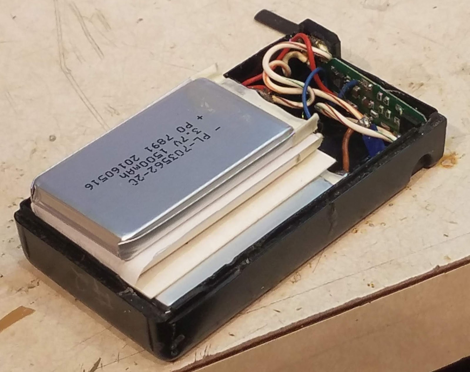
Figure 1:
The 10 year old pack.  The old cells have started to "puff up" -
a sign that they need to be replaced.  The separators between
cells for this pack were just thin cardboard.
Click on the image for a larger version
In 2009, I looked around for cells that would better-fit within the original "high capacity" battery case better than the 18650 cylindrical cells and after a bit of searching, I found the model number 703562-2C sold by Batteryspace.com (information on that cell may be found here) - a 1.5 amp-hour foil-pouch cell that is 7mm thick, 35mm wide and 65mm long and weighing only about 25 grams each (about 0.9 oz).

Taking careful measurements I determined that four of these cells - and the protection circuit - would fit in the case and wired in series-parallel, a 7.2 volt, 3 amp-hour pack could be assembled.  Amazingly enough, these cells are still being sold, available for less than $7.00 each plus shipping.

When using these cells - which are essentially foil pouches with explosive lithium compounds inside - it is imperative that one must take several precautions, including:
  • The use of a "protection" circuit.  Especially when using cells in series, you MUST include a circuit that prevents either cell from being overcharged or over=discharged:  Either state can (and will!) damage the cell, making it more prone to "rapid, explosive self-disassembly".
  • Include current limiting.  A typical "protection circuit" will usually offer overcurrent protection in the event that the terminals accidentally get shorted - and this is a good thing as these cells can produce tens of amps of short-circuit current.   The circuit I used does do this, but there is also a "thermal fuse" included as well for redundancy.  For this radio, 3-5 amps of protection is adequate and will prevent catastrophic results.
  • Allow room for expansion.  These foil-pouch cells will expand slightly with normal use and over time and they should not be packed tightly into the available space - this, to prevent the battery case from being forced apart when this happens, but also to prevent the cells from being crushed/damaged by their own expansion and posing a hazard.
In late 2018, I noticed that one of the two battery packs that I'd put together 9 years earlier had started to swell a bit indicating that they were now at the end of their useful life, so I ordered more cells - and this time, I documented the "rebuild" process.

Warnings and weasel words:

Because Lithium-Ion cells - and other cells - can be dangerous, and there is the possibility of damage or injury, I must insert a few warnings at this point:
  • If you wish to rebuild/build your own battery pack using LiIon - or other types of cells - it is up to you to take the required safety precautions when doing so, and to accept the risk should fire, explosion, damage, injury or even death result.
  • While I can offer advice on how to rebuild battery packs using these cells, I cannot control the quality of the cells, the safety and usability of the build or the way that it is used and implemented.  It is up to you to do due diligence when it comes to safely constructing/using cells and educating yourself on the best way to do - or not do it!
  • Appropriate care must be taken in the use and maintenance of this and other battery/cell types.  It is up to you to determine the most appropriate and safest way to do this. 
    Figure 2:
    The four LiIon cells to be used for the rebuild.
    Click on the image for a larger version.
  • I cannot be responsible for your actions or the results of those actions or any damage/injury that might result.  As mentioned above, make sure that you do your own research, and take due care to ensure the safety in the construction and use of a battery pack.

The rebuild:

Starting out with some "large" battery packs that I'd been using with my FT-530 (e.g. a "high capacity" pack, about twice the length of the original packs) I carefully removed the original contents - including the 2.5mm charging connector, and disconnecting/removing the metal connections for the "drop-in" charger:  Because we will NOT be able to use the original NiCd/NiMH charger, we will not be needing these.

Figure 3:
The four cells installed within the case.  2 mil Nomex sheets have been
placed between the two parallel cells with a 20 mil Nomex
sheet between the two series sets of cells.  The pairs of cells are "staggered"
to better-allow for the expected expansion of foil-pouch cells such as these.
The protection circuit may be seen in the upper-right corner of the pack.
Click on the image for a larger version.
Having on-hand the four LiIon cells required (e.g. 703562-2C sold by Batteryspace.com  - information on that cell may be found here) and a suitable 2 cell "protection circuit" capable of handling 3 amps or so (also available from Batteryspace.com) I set to work.

To prevent abrasion and possible shorting, each cell must be physically insulated from each other:  We do not want to have the possibility of the cells rubbing against each other - or the possibility of unwanted electrical contact.  For this, I'd used the thin cardboard such as that from a cereal box or a box of crackers when I first constructed the battery in 2009, but this time I used various thicknesses of Nomex (tm) sheet - a nearly-indestructible paper-like insulation material:  This is probably overkill as the thin cardboard had worked fine, but I decided to use it because I'd had it on-hand from another project, having obtained it via EvilBay.  The advantage of the nomex over the cardboard is that it is a bit thinner, allowing a bit more room in the pack in the "thickness" dimension.

Figure 4:
 The completed, rebuilt LiIon battery pack, held
together with some polyimide tape - which I
had on-hand.

Click on the image for a larger version.
As it turned out, the width and length of the cells was narrower and quite a bit shorter than the inside of the battery case:  If I could have found cells that were a better "fit" and no thicker I could have managed more than a 3 amp-hour (nominal) capacity for the battery pack.  These cells' thickness by themselves doesn't give much margin for the internal space within the case itself, but by staggering the centers of these cells a bit there is more room for expansion of the cells in their normal change in size as they are cycled and as they age.  The FT-530 case has several millimeters of additional clearance in the dimension of cell thickness to allow for such expansion.

Clear RTV (silicone) sealant/adhesive is used to hold everything together:  A thin layer is used between the two parallel cells to hold the Nomex sheet in place - and to hold the two cells together and more RTV is used to hold the two sets of cells at an offset.  The use of RTV is suggested as it is flexible and has some "give" - something that is absolutely necessary with these types of cells to avoid damage during their normal use and lifetime.

Charging:

One cannot use the original NiCd or NiMH charger for the "new" battery - instead, a constant-voltage, current-limited supply is used.  While this sounds complicated, I simply used an LM317 adjustable voltage regulator - the circuit being taken from the standard data sheet - depicted below in Figure 6 - with the exception that a 5k, 10-turn potentiometer is used to set the voltage, and there is an LED (with series resistor) placed across the output as an indication of applied voltage.

To charge, the regulated supply is set (nominally) to 8.2 volts and allowed to charge for 6-8 hours when powered from a 1-2 amp power supply, after which time the battery should be removed from the voltage source:  In the interest of longevity one should NOT apply charging voltage continuously as maintaining a battery at "full charge voltage" accelerates chemical degradation of any lithium-based rechargeable cell.  The precise amount of time to leave the battery "on charge" isn't critical:  It should be long enough to adequately charge the battery, but it should not be ignored and simply left for long periods.

It is certainly possible to find a cast-off or surplus "8.4 volt" LiIon charger intended for two cells in series and this device could be adapted.  The caveat to this is that this charger must have been designed for a "protected" battery pack - the clue to this being that the charger will have exactly two connections to the pack to be charged.  Of course, it will be up to you to come up with a way to make a connection to the original battery pack - perhaps in a manner similar to that depicted in Figure 5, below.

Making LiIon cells last longer:|
Figure 5:
Homebrew charger for the LiIon pack.  In the lower left is a connector,
made from circuit board material and hobby brass, that slides over the
top of the battery pack to make contact.  The circuit itself (upper right)
is built onto a heat sink and contains an LM-317 voltage regulator
circuit, an LED, and a 5k, 10 turn potentiometer to set the voltage.
The LED, connected on the output side of the regulator, illuminates
when voltage comes from the battery (e.g. to make sure that a connection
is made to a charger) or the 12 volt (nominal) power source for charging.
Click on the image for a larger version.

To further-promote longevity of the battery it has been suggested by battery manufacturers and other "experts" 1 - footnote that the charge voltage be reduced from the nominal 4.2 volt/cell value - a value of 4.05 volts/cell (or 8.1 volts charging) to double the lifetime (in terms of charge cycles) and slow the inevitable degradation over time:  This is likely one of the reasons why I got about 10 years out of the original set when a typical LiIon cell/battery will last about 5 years.

What about capacity loss from not "fully charging" the battery?  Charging to 4.05 volts/cell will yield about 80-85% of capacity as compared to a full charge of a new cell, but it is not uncommon for a new LiIon cell - charged consistently to the "full" 4.2 volts/cell - to lose 15-20% after the first year due to degradation.  What this means is that in the long run, the net loss is mitigated, anyway, also offset by the slower degradation of the cell over time by this same reduction in charging voltage.

Actual use:
Figure 6:
Circuit diagram of the LiIon charger - just a "datasheet standard" circuit
to regulate to the desired charge voltage.  The LED may be any color and
is used to detect when the battery is properly connected to the charger
and to indicate the presence of charge voltage.  U1, the LM317, should be
mounted to a heat sink.  Potentiometer R1 is adjusted to set the output
to the desired full-charge voltage.
Click on the image for a larger version.

Having used LiIon cells with my FT-530 for about 20 years now I would not go back to the NiCd/NiMH types again - except, perhaps, unless they were put in the 10-cell AA battery pack shell that I also have.  For many years my FT-530 has been programmed to turn itself on (using its built-in clock) in the morning to monitor a local repeater - and it will turn itself off after 30 minutes unless I hit a button or transmit:  If I only listen, the radio will go 2-3 months between charges when used this way.

In "heavy" use - such as a public service event where frequent transmission is required - I can use the radio at least "all day" at full power (2-2.5 watts output) without running it down.  When the cells are depleted, I get reasonable warning - particularly since the FT-530 has an on-screen voltmeter than may be enabled.

If I see the battery voltage drop below 6.9-7.0 volts during receive I know that I should consider finding the spare pack - and the radio will continue to work until the point at which the display starts to flash at about 5.5 volts.  Interestingly, the radio will quit (turn itself off) before the "protection circuit" kicks in due to low cell voltage - but little actual battery capacity is left anyway below 6.0 volts, so it appears that a "2S" (e.g. two series-wired) Lithium-Ion cells are a pretty good match for the FT-530.

Comment:  The FT-530 is capable of operating from up to 15 volts, so a "3S" (3 cell in series) pack is possible - but the limited space in this battery pack case means that, at least with these types of cells, that six of these cells cannot be put in series-parallel:  Three of these cells in series would yield a "10.8 volt" 1500 mAH pack rather than the nominal "7.2 volts" at 3000 mAH of the pack described here.

Use of LiIon Packs with other, older radios.

Until, perhaps, the early 2000s, many amateur handheld transceivers were shipped with NiCd or NiMH battery packs - and this shows that with proper care and attention to detail that it should be possible to retrofit one of these battery packs with modern LiIon cells, giving the original radio - which is still likely to be very usable these days - much more operational capacity out in the field.

Before "converting" such a radio, there are several things to consider:
  • The voltage range of the radio.  Keeping in mind that the voltage of a LiIon cell can vary from 4.2 volts, freshly off the charger, down about 3.0 volts meaning that a hypothetical 2-cell battery such as this can produce between 8.4 and 6.0 volts, spending most of its operating time in the 6.8-7.2 volt range.  If, in this 2-cell example, your radio can happily operate in this voltage range, your radio might be a good candidate.
    • Other examples:
      • 3 cells:  9.0-12.6 volts, spending most of its time in the 10.2-10.8 volt range.  May be usable for radios that are capable of operating directly from a 12 volt supply.
      • 4 cells:  12.0-16.4 volts, spending most of its time in the 13.6-14.4 volt range.  Many "12 volt" capable radios have an upper voltage limit of 15.0 volts, so this may be too high for safe operation with a freshly-charged battery. 
  • A means of charging.  Make sure that you can charge any battery that you might put together.  In my case, I built a very simple charger (see figures 5 and 6) but I could have adapted an old LiIon charger - or even used a bench-top power supply that was properly adjusted for the charge voltage.  If your radio has some means of built-in charging, it probably cannot be safely used.
  •  A usable battery pack case.  In many instances one can re-use the original battery pack's case and stuff into it appropriately-sized cells as was done here.  If one does this it will be necessary to carefully measure the internal dimensions and find the prismatic cells that will fit inside - remembering to allow room for the "protection circuit".
* * * * * *

Footnote:

1 - "How to Prolong Lithium-Based batteries" - https://batteryuniversity.com/learn/article/how_to_prolong_lithium_based_batteries


This page stolen from ka7oei.blogspot.com

[End]