A couple of months ago I had also gotten a clone of the AVR ISP MkII with which AVR projects that include the ICSP (In Circuit Serial Programming) interface can be programmed, but the Ultimate 3 kit didn't have the ICSP pins of the processor broken out on the board so I had to build a stand-alone circuit with which I could program the chip after having been removed from its socket on the Ultimate 3 board.
Figure 1, below is the result.
 |
| Figure 1: The ICSP Interface board 8 and 28 pin AVRs built onto a 1-3/4" x 1-1/2" (approx. 45 x 40mm) prototype board. The 6 pin ICSP connector may be seen along the right side of the board. (Yes, I know that the label says "8 & 20" pins - I changed it after taking the picture...) (Click on the image for a slightly larger version) |
In looking on the GoogleWeb I saw a plethora of diagrams showing how these chips would be connected to either a 6 pin or 10 pin ICSP connector, so I built the board above (sans oscillator at first - more on that in a moment) and tried to read the chip's signature....
It didn't work.
Oops - I'd forgotten a power supply, as the AVRISP MkII programmer didn't supply power to the chip being programmed. No problem: I threw a 78L05 and a pair of 0.1uF capacitors on the board so that I could supply a stable, clean source of 5 volts externally. Connecting the programmer again it now read 5.1 volts via the ICSP connector. I again tried reading the chip's signature.
It still didn't work.
Trying the programmer on an Arduino board I verified that it actually worked - and then I remembered that there was a very good chance that these AVRs would need a clock source in order to function. Rummaging around in my collection of resonators I found a 3-lead 4.0 MHz ceramic resonator with built-in capacitors and plopped it onto the board.
Success!
For some reason, I decided that that wasn't enough: I thought "What if the fuses on the chip were configured to take an external clock source and the device was not configured to an external crystal?" - could an AVR be configured to be that way - even during programming? Rather than research that point I decided to completely circumvent the issue and put a 4 MHz "can" oscillator on the board instead of the resonator and connect it to the clock/crystal input pin of the AVR designated as "XTAL1" on each of the two sockets.
At the moment I have only a few AVRs with which to test: One of them was configured to use a 20 MHz crystal while the other was set up to accept an external oscillator for the clock. When originally tested with the 4 MHz ceramic resonator, the one configured to use the crystal did work in this circuit but the other one did not. Once I changed to a 4 MHz oscillator module they could both be read and written.
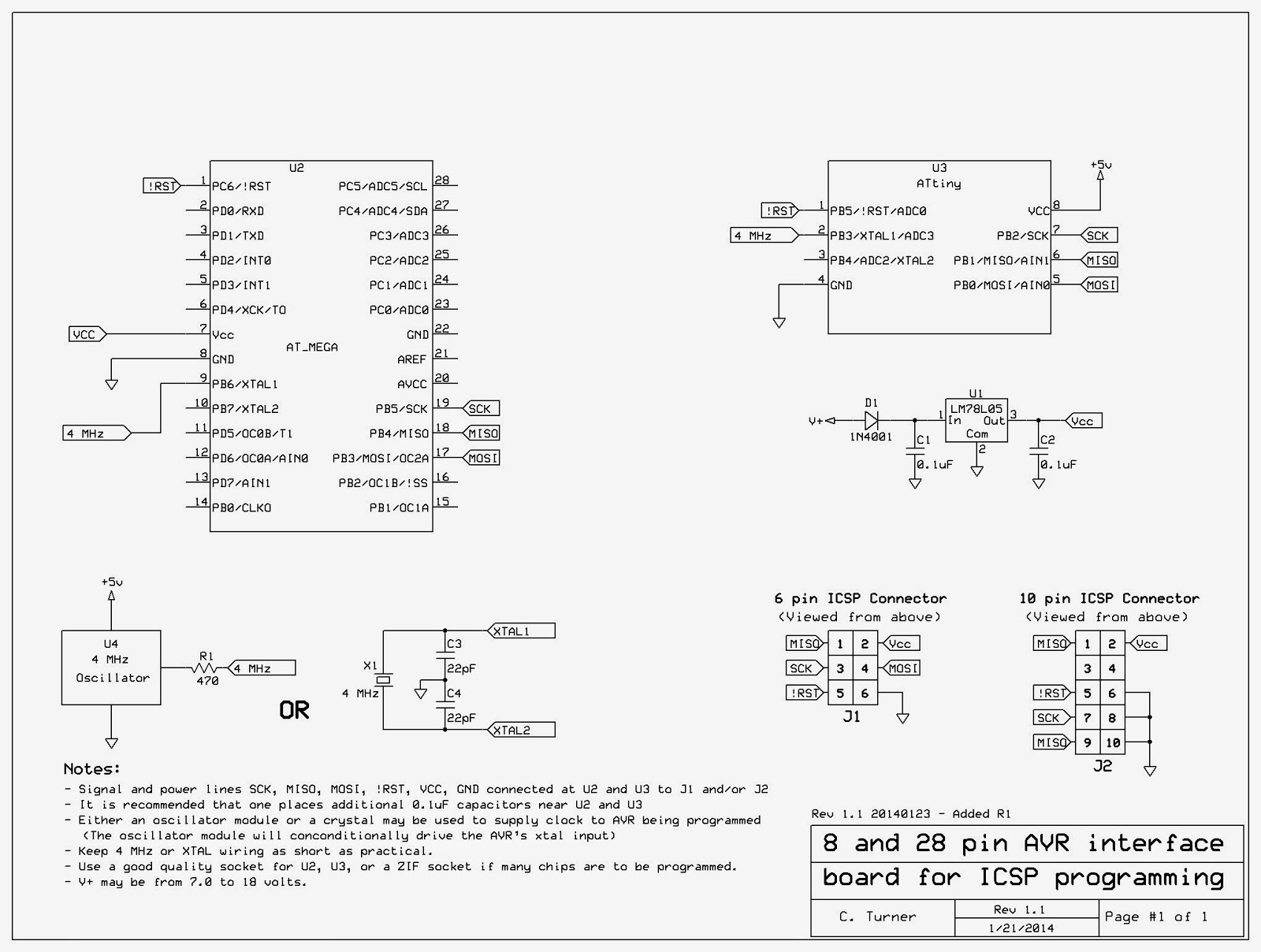 |
| Figure 2: Schematic diagram of the AVR ICSP interface board (Click on the image for a larger version) |
In Figure 2, above, you can see the final result and some notes.
I find it quite interesting that while I could find the ICSP connections for the AVR all over the InterWeb (or is it GoogleFace?) I could find not one of them (at least in the first half dozen pages of results...) that actually made mention of the need for a clock source or a self-contained power supply! The assumption seemed to be that anyone, anywhere, would include the ICSP connections on their project board, already and never have a need to program a "free-standing" chip.
While my programmer has only the 6 pin ICSP connector I dug up the 10 pin connector pinout for the convenience of someone else who might have that. I also included in the notes the option of using either a ceramic resonator/quartz crystal OR a 4 MHz "can" oscillator.
Later, I decided to add R1 on the oscillator module's output - just in case the fuses on the processor had been set to cause this pin be a logic output as might be the case if the AVR's internal oscillator is used - in which case, it probably wouldn't need any external crystal or oscillator at all. The 470 ohm resistor allows the line to be driven easily, but limit the current to a very safe value were it set to a 0 or 1.
Note:
The actual frequency of the crystal, oscillator or resonator is not important, but it must be within the ratings of the processor being programmed at the operating voltage provided by the programming circuit. Also, the programming clock speed - selectable in the programming software - must be no faster than 1/4th of the oscillator/crystal/resonator frequency.
The default of 250 kHz is used in the version of Atmel Studio that I was running. Anything in the 1 MHz to 8 MHz range for a crystal, resonator or oscillator module is likely to work equally well. If the AVR is configured to use a very slow internal oscillator, the programming software would need to have its programming clock frequency changed accordingly.
While I used a 78L05 for the voltage supply to the chip being programmed, about anything that provides a stable and clean source of 3.3-5.5 volts would probably work (you'd have to verify the operating voltage range of the processor that you are programming) and this could even include the use of 3 AA or AAA cells in series to get 3-5 volts, the exact voltage depending on the condition of the battery.
If you do use a battery to provide power for the processor during programming make sure that there is at least one 0.1uF capacitor located near-ish U2 and/or U3. If you use the crystal can oscillator with a battery you will need to add an on/off switch, but if you chose to use the crystal or ceramic resonator, instead, you could forgo the switch - provided that you never left a processor in either the U2 or U3 socket when done!
Comment:
A switch may be a good idea, anyway as it is recommended that one removes the power before plugging in or unplugging the processor from its socket - but I will admit that I frequently don't bother doing that and have never had a problem... yet...There are AVRs out there than those with 8 and 28 pins - and maybe even some 8 or 28 pin devices with pin-outs that don't match Figure 2, but the 8 and 28 pin versions for which the sockets are wired are the two sizes for which I expect to have immediate need.
One thing that the AVR ISP and this board cannot deal with is if the AVR's LVP (Low Voltage Programming) has been disabled. If you configure an AVR such that this feature is disabled it is possible that you will need to seek out a programmer with "High Voltage Programming" to reset the fuse and re-enable LVP.
My prototype board is only 1-3/4"x1-1/2" (approx. 45x40mm) so there wasn't really enough room to put anything on it other than what I did - and I was barely able to cram the 4 MHz can oscillator on the board as it was!
[End]
This page stolen from ka7oei.blogspot.com
No comments:
Post a Comment
PLEASE NOTE:
Be sure to be logged in to your Google account to post.
While I DO appreciate comments, those comments that are just vehicles to other web sites without substantial content in their own right WILL NOT be posted!
If you include a link in your comment that simply points to advertisements or a commercial web page, it WILL be rejected as SPAM!