Monday, June 30, 2014

A 100 watt "Helical" resonator bandpass/notch filters to increase isolation of 20 meter stations during Field Day

Follow-up:
For another article with more measurement and analysis of these filters, see the 31 May, 2019 article - Revisiting the 20 meter "helical resonator" band-pass/notch filters- linked here.

As with many groups, the Utah Amateur Radio Club (UARC) operates both a CW and SSB station on 20 meters during Field Day.  Being that 20 meters is typically one of the "prime" bands where most of the contacts are made during daylight hours and often into the night, it would make sense to optimize operation on that band as much as possible.

Despite separating the antennas as far as is practical with the available geography - about 300 feet (approx. 100 meters) - and arranging the Yagis north-south of each other so that they are pointed generally broadside each other (east/west) for U.S. coverage, we occasionally encounter a bit of interference between the SSB and CW stations on the same band.  This isn't too surprising because, at times, the transmit frequency of one station is just 100-150 kHz away from the receive station of the other and with stations so close together - in terms of frequency and proximity - they are bound to "interfere" with each other, at least occasionally!

Unfortunately, "normal" filtering schemes that one might initially consider don't really apply here.  The methods and means of filtering that one might see applied at HF stations include:
  • Tuning stubs using pieces of coaxial cable - typically in 1/4 and 1/2 wavelength segments.  These are typically used to "notch out" signals from, say, 20 meter operations that are bothering a 15 meter station.  This can happen because many radios filter the band(s) below the rather poorly on receive and/or a 15 meter transmitter will often generate low-level noise on 15 meters and all bands below it which can often be problematically radiated by multi-band antennas such as Yagis.  The "noise problem" is mentioned in more detail, below.
  • Commercially-available bandpass filters (e.g. "Dunestar" ).  This filter would be used to mitigate the same sorts of problems as the notch/stub coaxes mentioned above, but in smaller, more convenient packages.
  • Tunable L/C traps using transmitter variables and standard inductors.  Using the sort of components that one might use for high-power antenna tuners, it is possible to construct L/C filters through which one can transmit that could be used to tune notches to eliminated "problem" signals.  Unfortunately, these are somewhat complicated to use and rather large, so they are rarely seen.
The reason why the above really aren't useful (at least for transmitting) is that they simply don't have a high enough effective "Q".  All that can really do is keep one band (say, 20 meters) out of another band (say, 15 meters) - That is, you couldn't expect it to affect, say, a signal at around 14.050 MHz and have minimal effect at 14.150 or vice-versa since it is impractical to make tuning that sharp using the methods above.  What's worse, if you do build a narrow enough filter to remove a station that is, say, 100 kHz away from you, it has fairly high insertion loss:  This may work for receive if you can separate the two signal paths in your radio, but you certainly can't transmit through it.
Figure 1:
The two 20 meter "Helical" resonators.  The one on the left is a "notch" only
filter used on the SSB station to remove the CW transmitter's energy and the
energy of the SSB transmitter from the CW passband while the one on the right
is a passband filter used with the CW station, both to keep the SSB station's
energy out of its receiver and to reduce low-level noise from the CW
transmitter in of the SSB station's passband.  They are capable of handling
at least 100 watts of RF and the loss caused by the use of
either one of them is on the order of 1dB or less when the coupling is set
for 10-15dB (about 2 S-units) of attenuation at the frequencies to
be rejected.
Click on the image for a larger version.

What's more is that most transmitters produce a low-level, broad-band noise spectra when keyed up that can blanket the entire band - not to mention, sometimes, low-level spurs related to who-knows-what that can sometimes land on the other station's receive frequency.  Even if these spurs are 100 dB down, they may still be strong enough to be an annoyance to the other station on the same band.

A similar noise problem can also exist in a receiver, seemingly created out of nothing even if the transmitter is completely "clean" - a response to various noise sources in the receiver chain in the presence of strong signals.

The situation can seem hopeless, then, if you can't manage to get a huge amount of geographic isolation and/or higher-end rigs that purport to have (or actually have) ultra-clean transmitters and receivers with super-high dynamic range and ultra-clean oscillators.

Or is it?

A few years ago I decided to see if it was possible to make a "20 meter Helical Resonator" so I dug out the formulas, crunched some numbers and observed that such a filter would be possible with practical (and relatively cheap!) materials - just.

Figure 2:
The coil wound on the glass jar along with the
coupling probe.  This particular filter was lined
with copper foil, but it turned out not to make any
difference, so I didn't bother lining the next one!
Click on the image for a larger version.
I went to one of the big-box home improvement stores - Lowes-Depot, I think - and got several one-gallon, metal paint cans.  Noting that their very thin metal construction made them a bit flimsy I decided that they would require a bit of reinforcement to make them mechanically stable but the main requirements - being cheap and 100% metal - were satisfied.  Technically, they were just a bit undersized for a true 20 meter helical resonator, but I figured that if this didn't work, it would be a relatively inexpensive failure.

A friend of mine gave me a chunk of #6 solid copper wire, but copper tubing of a similar outside diameter would have worked just as well, would have been lighter weight and probably have been easier to work with:  Aluminum wire would have worked reasonably well, too, although a larger size (say 4 AWG) would be preferred to overcome the losses compared to those of copper - but it would be a bit more of a challenge to make low-loss, reliable electrical connections.

I wound the wire on a smaller form - some plastic pipe that was 3-1/2" (approx. 9 cm) diameter - and then forced it over an empty "Adams" (tm) peanut butter jar which was just about the right height and diameter to fit inside the 1 gallon can and being made of glass, was already a low-loss material that would have no trouble at all standing up to the high RF voltages that would be present.  Initially taping the wire to the glass, I used RTV ("Silicone") adhesive in several places to secure the turns, avoiding its excess use as I wanted to keep the losses as low as possible.

Comment:  The dimensions of the glass form - the peanut butter jar - are approximately 4-1/8"(10.5 cm) outside diameter and 7-1/2" (16.5 cm) tall.  The coil was wound on approximately 4-1/2" (11.5 cm) of this height.

Having initially wound the wire over a smaller form caused it to fit fairly tightly over the larger, glass form, so it "took" well to staying in place while I carefully separated the turns equally and secured their positions.  Note:  After the RTV had cured, the tape that had been used to temporarily hold the turns in place was removed.
Figure 3:
 The mounting of the SO-239 connector on a piece of aluminum
plate for a more stable platform.  This is riveted to the side of the
paint can, but it could have been screwed in place.  This
particular connector was attached at the seam of the can to
take advantage of the thicker metal there.
Click on the image for a larger version.

Winding more turns than I expected that I would need, I set the coil aside for a day or two to allow the RTV to cure and constructed a capacitive coupling probe from a copper plate that was bent to a radius that (more or less) matched that of the coil - See Figures 2 and 6.  This plate was actually made from the shield of a scrap of "Heliax" (tm) cable that was cut length-wise and then pounded flat.  Between the relatively thick copper of the shield material and the "work hardening" from manipulating this copper, it was pretty stiff - especially after bending it to the radius.  Copper flashing could have also been used, the edges rolled away from the coil form to increase rigidity.

For a connection to coaxial cable I cut a piece of 3/16" (4.8mm) thick aluminum plate that was about 2 times the length of an SO-239 connector and about 1.5 times its width, formed it using a hammer and piece of heavy pipe to the same radius as the paint can, mounted the SO-239 connector to it and then pop-riveted the assembly over a hole that I'd made in the side of the paint can that aligned with the top of the coil.  See Figure 3.

Inside, I connected the center conductor of the SO-239 connector to the copper coupling plate using a length of #12 AWG solid copper wire, forming a capacitive coupling probe which was adjustable in position relative to the coil by virtue of bending both the coupling plate and the wire connecting it to the SO-239 connector.  Picking the same spot on the opposite side of the coil, I duplicated the connector/coupling probe arrangement and put one there as well.

Now, the tricky part:  Setting the frequency tuning range.

Placing and centering the coil in the paint can, the bottom end was grounded via a hole that I'd drilled in the side of the can for that purpose.  I also placed the coupling probe about 3/8" (9-10mm) from the top of the coil as a starting point for determining resonance and coupling, knowing that this was likely to change.  Using an antenna analyzer I swept the frequency up and down and saw a very prominent deflection that I believed to be the self resonance of the coil at around 12 MHz in my case - and placing my hand near the top of the coil and causing the frequency to shift downwards due to the added capacitance confirmed this.  Taking a fraction of a turn off at a time, I soon moved the frequency up to around 14.5-15 MHz.
Figure 4:
A tuning disk of double-sided, glass-epoxy circuit board
material that was cut using a hole saw and soldered
to the threaded rod.  This disk must be as flat/parallel to
the lid as possible and remain so during rotation
for smooth, even tuning.
Click on the image for a larger version.

In the center of the paint can lid I drilled a hole large enough to accommodate a 1/4"-20 nut and de-burred it.  On the top side of the lid I soldered a brass 1/4"-20 nut using plumbing solder and a hot soldering iron rather than a torch as the latter would have likely ruined the can's plating and made soldering much more difficult.

For the paint can lid I cut a round piece of wooden paneling about the diameter of the lid with a hole saw and made a hole in its center large enough to accommodate a 1/4"-20  nut.  and used RTV to attach it to the top side - this, to stiffen it and prevent it from wobbling during adjustment - see Figure 5.

Onto some threaded rod (brass rod is easiest to work with) I soldered a disk of glass-epoxy circuit board material - also cut with a hole saw - to form a capacitive plate that would go up and down to allow tuning, making this disk as close to a right angle to the rod as possible (e.g. parallel to the lid) so that when rotated, the disk maintained an even distance to the top of the coil as it went up and down.  If the disk isn't perfectly "flat", the frequency will be seen to "wobble" up and down while adjusting the tuning.  This same sort of thing can happen if the disk isn't perfectly round and the hole isn't centered, but cutting it with a standard hole saw reduces those problems.

The metal from which this disk is cut isn't really important as it could be also be aluminum or even steel:  It just needs to be stiff, flat and round.  If it cannot be soldered to the threaded rod - which may be the case if steel/stainless threaded rod was used -  then the disk may be electrically "connected" using 1/4"-20 bolts and some lock washers as the protrusion of the bolt through the center should have minimal effect except for the fact that the bolt on the "top" side will prevent the disk from being adjusted as close to the lid of the paint can and slightly reduce the tuning range.  Note:  In Figure 4 I used double-sided circuit board material.  If single-sided circuit board material is used, place the copper side down, toward the coil.

The rod was then threaded through the bottom of the lid of the paint can and a lock (e.g. "split") washer and a flat washer along with another nut used as a "jam" nut were spun onto the rod to give it a bit of tension and the threaded rod was then lubricated with a drop of oil to make its operation smooth.  As can be seen in Figure 5, a piece of scrap wire from the coil was soldered to this nut and secured with small straps to maintain the tension on this jam nut.

I set the disk as high as it would go (against the lid), installed the lid and then re-checked the frequency and as expected found that it was again low (around 13 MHz) due to the capacitance of the metal lid itself as well as the disk and then did more trimming of the coil, a process that required repeatedly taking the lid off, trimming the coil, and putting it back on again to check.

Eventually, I got to the point where I could tune through the 20 meter amateur band and was ready to do some initial testing.

Using an HF transmitter set to just a few watts and a VSWR bridge and combination power meter on one side and a 50 ohm dummy load and another power meter on the other side, I tuned through resonance and noted that I had both a high amount of insertion loss and a high VSWR at resonance.
Figure 5:
The top of the can, reinforced with a disk of thin paneling/
plywood that had been glued to the top with RTV to make the
thin metal top of the paint can much more solid.  Soldered
to the lid - but not visible - is a brass 1/4-20 nut through which
the tuning rod is threaded.  There is a flat and split ("lock") washer
used to set the tension and the piece of copper wire seen in
the picture above is used to prevent the jam nut from
spinning as the knob is turned.
Click on the image for a larger version.

I moved both of the the coupling probes equally closer to the coil itself and taking a bit more of its winding off - as the proximity of the probes actually lowered the resonant frequency.  After a few more iterations of trimming the coil I found a point where I was able to get around 80% of power to pass through the filter at resonance (about 1dB loss) and a reasonable VSWR - less than 1.5:1 - and achieve a bandwidth of only a few 10's of kHz:  This would be my CW station bandpass filter!

Notes: 

  • Had I cut too much wire off and raised the frequency too high I would have simply soldered - using a very hot iron - a short piece of pre-bent, to match the curve of the glass - section of #12 or #14 wire, to extend the top of the coil:  At the very top, the thickness of the wire in the coil at the top ("high voltage") end is less important in determining its loss characteristics and a few inches/centimeters of smaller-diameter wire here will have no ill effects.
  • Avoid the temptation to increase the coupling too much to reduce losses much below 1dB or so.  If you do this, the resonator will be over-coupled and its filtering effects in the SSB portion of the band will be reduced.   If the transceiver has a built-in antenna tuner to help sort out the mismatch that may be caused by the insertion of one of these filters - particularly as you move away from the center frequency - by all means, use it!
  • It is in the "narrowness" of the filter that the importance of using large outside-diameter conductor for the coil becomes important.  The first attempt at a bandpass filter used 12 AWG wire and dramatically inferior results were experienced, with the filter offering only 3 dB or so of attenuation 100 kHz away on 20 meters.  The #6 wire used in these coils was probably a bit overkill and #8 AWG would have probably been fine, as would copper tubing of similar outside-diameter (e.g. 3/16" or approx. 4mm outside diameter.)  Remember:  RF flows on the outside of the conductor, so there's no real need to use a solid conductor for the coil - but make sure that you use only clean copper or silver-plated material for it.  Beyond a certain point, however, the "loaded Q" - that is, our coupling (via probes) into the coil to put our transmitted energy into it - and then take it back out again - becomes dominant and "improving" the coil itself even more by using still-larger wire, for example, reaches a point of diminishing returns.
Once I was satisfied that I'd gotten the tuning where I'd wanted it I carefully attached the glass peanut butter jar to the bottom of the paint can with plenty of RTV adhesive to the bottom of the same can. On the bottom (outside) of the can I "RTVed" another disk of scrap of wooden paneling that I'd cut with a large hole saw (or freehand) to prevent the thin, metal bottom from wobbling and affecting the tuning.  I then set this assembly outside in the hot sun for a few days with the lid removed to let the RTV cure.


A "Notch" filter:

I then replicated the above - but this time, I built a filter with just ONE coupling probe:  Instead of a bandpass filter, this would be a "suck-out" (e.g. "Notch") filter.

For adjusting the coupling of the notch filter, the easiest way is this:
  1. Connect, using a UHF "Tee" connector", to a radio and a 50 ohm dummy load with a VSWR meter connected between the radio and the Tee connector.
  2. Set the notch at 14.050 MHz (or the desired 20 meter CW frequency) using an antenna analyzer.
  3. Tune the radio to 14.150 and connect it inline with the notch filter.
  4. Transmit into the dummy load with the notch inline and note the VSWR.
  5. If the VSWR is lower than about 1.3-1.5:1, move the coupling probe closer to the coil, noting that you'll have to re-tune the coil - possibly removing some wire.  The idea here is to increase the coupling - something that will raise the VSWR a bit - the target being around 1.3: to 1.5:1.
  6. Go back to step 2 as necessary.
Note that a VSWR of 1.3-1.5:1 will not adversely affect operation - particularly if your radio has a built-in tuner - but it does indicate that the notch is just starting to have an effect.  If you have the means to do so (e.g. tracking generator and spectrum analyzer or signal generator and high-sensitivity power sensor) you can verify that at the notch frequency.

From experimentation, it has been determined that at about 100 kHz away from the notch, when the notch filter itself causes a VSWR of about 1.5:1 to occur in an (otherwise "flat" 1:1 match) it will notch out the energy at the notch's center frequency.


Note: 
As can be see in Figures 2 and 6, I lined one paint can with copper foil.  The other filter, I left alone, with its original gray protective paint inside the pain can:  There was no difference in apparent "Q" or performance between the copper and steel!
This result was not unexpected as the current is rather widely distributed along the inside of the "cavity" and the ohmic losses there are of less importance than those of the coil itself.  Any future duplications of these filters would not use copper foil lined cans.

How the two filters are used at a Field Day site:

With both a bandpass filter and a notch filter available at a Field Day site, the two are used in combination thusly:

Figure 6:
A closer view of the capacitive probe and its connection to
the SO-239 connector.  This arrangement is somewhat
flimsy, mechanically, and should be re-thought.
This particular filter was lined with copper foil to see if
performance was improved over the plated, painted interior
of the original paint can:  No improvement was noted.
Click on the image for a larger version.
  • The Bandpass filter is placed on the CW station, in series with the transceiver.  With its usable passband of +/- 15 kHz or less, it covers a reasonable chunk of the 20 meter CW passband, but it is easily retuned by a operator who simply turns the knob on top while watching the reflected power and will attenuate energy from the SSB station at 14.150, the amount of attenuation increasing as one moved up the SSB portion of the band.  This passband response will reduce not only the signal level from the SSB station to minimize the possibility of receiver overload, but will also attenuate any broadband noise that the transmitter might produce that could degrade the 20 meter SSB operation.  Most CW operation occurs within a 10-15 kHz of a central "spot" - particularly if one "runs" a frequency - so frequent retuning is usually not required.
  • The "notch" filter is connected "across" the SSB station's transceiver coax with a UHF "Tee" connector, but is tuned for the center of the CW passband where such operations will take place.  At SSB frequencies, it has practically no effect whatsoever, but at the CW frequencies will be attenuated, minimizing both overload by the CW station and also notching out broadband noise that might be produced by the SSB transmitter itself that might degrade reception at the CW frequencies.  As long as the SSB operator doesn't transmit anywhere below 14.125 (which should never happen!) the VSWR will be practically unaffected.

Does it work?


Yes, actually.  While we haven't needed it every year (we don't know why we can get away without it some years even though we have been using the same rigs and antennas for years now...) when placed into service, it does completely remove - or very much knock down - inter-station interference between 20 meter operations while easily handling the 100 watt output of the radios that we are using.
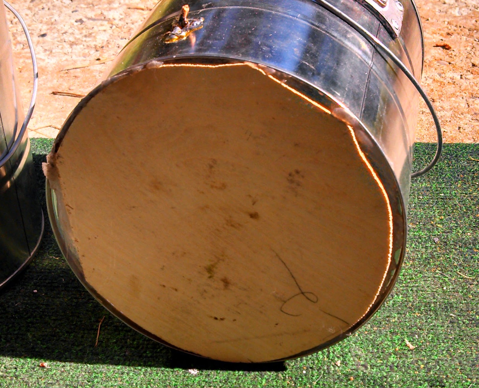
Figure 7:
The bottom of the paint can, reinforced with a piece of thin
plywood/paneling to keep the glass coil form from wobbling
about.  This piece of wood is attached using RTV adhesive
and allowed to cure for several days before handling.
Click on the image for a larger version.


Notes on these filters:

  • Paint cans are quite flimsy.  As you can see from the pictures, several measures had to be taken to "beef up" the paint cans with pieces of paneling to overcome their inherent mechanical instability.  Without these steps, tuning  could be radically affected by just touching the top of the filter, the weight of the coax hanging on the a connector, or just bumping it while handling it!  Even after doing all of these things they are still quite fragile and likely to be de-tuned (or broken!) if dropped!
  • They are a pain to tune the first time - and a bit of a pain to set up at each Field Day!  After the initial tune-up, you need to have on-hand an antenna analyzer to know where the notch is and a reflectometer (e.g. VSWR meter) - or better yet, a VNA - is imperative for the CW station to know when the bandpass filter is centered on the operating frequency.
  • There's no practical reason why similar filters couldn't be constructed for the 10 and 15 meter bands - or other frequencies in between. For lower bands (e.g. 40, 80) you would need much larger cans:  Think "bucket" sized!
* * *

Note:
For follow-up article with more measurement and analysis of these filters, see the 31 May, 2019 article - "Revisiting the 20 meter "helical resonator" band-pass/notch filters" - linked here.

Sweeps of these filters and analysis:
Figure 8:
A frequency sweep of the notch filter, tuned to the CW segment of 20 meters.
The measured notch depth was on the order of 10 dB.  This filter is designed to
be placed in the feedline of the 20 meter SSB station to reduce energy from
the 20 meter CW station.
Click on the image for a slightly larger version.

The Notch filter

After several years of having been used, I finally got around to "sweeping" them using a spectrum analyzer.  Not having a tracking generator on-hand, I used a broadband noise source, setting the resolution bandwidth to 3 kHz to provide the needed frequency resolution and the video bandwidth to 10 Hz to "smooth" the trace.  The result of sweeping the notch filter may be seen in Figure 8.

Admittedly, the depth of this notch is as great as I'd hoped and while I was at it, I did a bit of experimentation - moving the capacitive coupling probe closer and farther away from the coil.  As it turned out, moving the probe closer to the coil widened the notch and reduced its depth even more while moving the probe away narrowed the notch and also reduced its depth.  This result implies that the notch depth is, at least in part, limited by the unloaded "Q" of the coil within:  You may recall that this effect was briefly mentioned above when I originally wound the coil with 12 AWG wire.

How do I improve the performance?  There are several options:
  • Use a larger coil.  As noted above, 1 gallon paint cans are a bit small for 20 meters, so a "full sized" coil would probably have a better unloaded "Q", but something larger than a paint can would be required.
  • Use larger conductor for the coil.  The 6 AWG wire is 0.162" (4.1mm) in diameter and being wire, it is solid - and heavy.  Because of the "skin effect", RF energy flows only on the outside of the conductor, so tubing may be used, instead with the added advantage of being lighter and a bit easier to handle.  Obvious alternatives are "1/4" inch tubing (actual O.D. of 0.375", 9.5mm) and "3/8" inch tubing (actual O.D. of 0.5", 12.2mm) which would increase the surface area by a factor of and 2.3 3, respectively, significantly reducing the RF resistance - but it would probably be difficult to fit a "larger" coil within a 1 gallon paint can.
  • Reduce the loss of the coil former.  As noted, the coil is supported by a glass jar with the windings held in place with blobs of RTV.  While glass is a pretty good choice for this task, a "skeletal" coil former made of polycarbonate or other low-loss plastic would offer slightly lower loss, be much lighter in weight and allow the coil to be trimmed/lengthened somewhat more easily.  Even if it has only a small effect as compared to that of using a larger conductor, it would be worth doing owing to the savings in weight and being designed to be specifically suited for the task at hand.
  • Use more than one pass/notch element.  Cascading notch and/or band-pass resonators will improve off-frequency rejection and allow better control of the shape of the pass/reject band.
Increasing the size of both the container and the conductor would and the selection of appropriate stubs, etc., I'm certain, make a very significant improvement in the depth - probably permitting 20 dB or more at the center frequency while also making this notch a bit narrower.

One thing that somewhat improved the notch (by 3-4 dB) was using a stub of less than 1/4 wave (electrical) length piece of coaxial cable between the signal source and the notch cavity:  The lower impedance of the notch is transformed to a higher impedance at the "radio" end by this stub section, slightly deepening the notch.

While the notch depth is "only" around 10dB this still represents a significant decrease in the energy from another transmitter.  If one takes the oft-quoted advice that states that 1dB increase in signal represents 3dB in undesired mixing products at face value, things like intermodulation distortion in the receiver can be easily reduced by 20 dB or more.

Figure 9:
A frequency sweep of the band-pass filter, tuned to the
center of the 20 meter CW band.  This filter is designed
to be placed inline with the CW station to reject energy from
the 20 meter SSB station - and other stations on other
bands.
Click on the image for a slightly larger version.
The bandpass filter:

Because it is identical, the bandpass filter's response is also a bit worse than I was hoping - and for the same reasons as the notch filter.  In doing experimentation, moving the probes closer expectedly increased the bandwidth, but moving them farther away did not narrow the bandwidth much and significantly increased the insertion loss - yet another indication that the unloaded "Q" of the coil is a bit poorer than desired.

As can be seen from Figure 9, the attenuation at a frequency 220 kHz removed (about 14.250 MHz) is only about 6 dB, or 1 S-unit while the insertion loss at the center frequency was just under 1 dB.  To increase the "Q", the same sort of things mentioned above could be done to improve the coil and this would further increase the off-frequency attenuation while maintaining the same amount of loss - but at the expense of commensurately reduced pass-bandwidth.  As noted above, in the case of the CW station, it is very easy to retune the filter as one moves around in frequency (e.g. watching the reflected power while transmitting and adjusting the tuning) or one can, to a limited extend, rely on the antenna tuner to take some of the resulting mismatch into account without causing much additional loss.

Figure 9 reveals a few other things as well:  It functions well to remove energy from stations operating on other bands.  For example, the filter will attenuate 30 and 40 meter signals by more than 60dB while knocking down 17 and 15 meter signals by more than 40dB.  Another thing to note is that the passband sweep is somewhat asymmetrical:  The attenuation at a given frequency is somewhat greater below the center frequency than above.  To a degree, this is due to fact that the percentage difference in frequencies above the center frequency as represented on the plot is lower than those below the plot, but it is also typical of capacitive coupling.  If inductive coupling were used, this response would be somewhat more symmetrical - but experimentally adjusting the amount of coupling in such a filter is decidedly more difficult to do!

* * *

Comments on the rigs that UARC uses for Field Day:

The rigs that UARC has used for the 20 meter stations for several years have been old Kenwood TS-450SATs - the ones with built-in antenna tuners.  We have "standardized" on these since they seem to be relatively clean and able to withstand strong, nearby signals - even on the same bands - as compared to other rigs.  We have "discovered" a few interesting things, however:

Most radios produce "Below Band" noise spectra when keyed up:

Almost all modern, solid state rigs from all manufacturers tend to put out a noise spectra that blankets all HF frequencies ON and BELOW the band on which they are being operated.  What this means, is that if you are operating on 20 meters using a multi-band antenna such as a Windom or Yagi, when that radio keys up on 20 meters, those operating on 20 meters and lower and lower bands will experience an increase in the noise floor - even if there is no modulation!

Note also that this noise could also appear above the current band, depending on the low-pass filter.  For example, it could be present on 17 meters when operating on 20 meters if those two bands use the same low-pass filter, but this depends on the radio's design.

In the case of the TS-450s with the built-in antenna tuners, we have found that simply enabling the antenna tuners - even when operating into a 50 ohm load and the tuner isn't really needed - will attenuate this noise by 15-40 dB on all other bands by causing the tuner to function as a low-Q bandpass filter for both receive and transmit and for this reason there is now a label on all of our TS-450s admonishing the operators to always keep the antenna tuner inline!  After all, no-one really notices the extra 0.25-0.5 dB or so (measured!) loss that the tuner causes at or near 50 ohms!

As noted above, other ways to eliminate transmitter-related noise and QRM on other bands include:
  • The use of 1/4 and 1/2 wave notch/stub coaxial filters.  These are band-specific and notch ("suck out") the frequencies for which they are tuned will leaving other frequencies unaffected... more or less.  One must make sure, however, that when changing bands, that the notch is removed and (if needed) replaced with the appropriate notch for another band to prevent a different interference problem or, above all else, you must make sure that you do not transmit on the band for which the notch you currently have installed is tuned!
  • The use of commercial, high-power bandpass filters such as "Dunestar" (tm).  These are fairly broad, bandpass filters that cover (more or less) an entire amateur band.  These do a decent job of knocking down out-of-band energy on both receive and transmit, but they can be quite expensive to implement - particularly if you have a set of these at each station!  As with the notch filters, they must be changed when you change bands!

A notable exception to this seems to be rigs with tube finals.  This isn't too surprising as the Pi network output of these rigs is inherently narrowband - as is often the preselector/driver - so they are practically incapable of producing broadband noise that extends outside the currently-operating band!  Because of the receiver's preselector front end that these same radios typically have, they also seem practically immune to QRM from operation on other amateur bands as well!


Certain radios are banned from our field day site!

The one radio that is explicitly banned from our Field Day site is the Icom IC-706 and its relatives of the same/similar vintage.

When this radio first came out, one was set up as the 20 meter SSB operating positions and within a few minutes of Field Day having started we had to take it off the air because it made operation of the 20 meter CW station - as well as the 40 meter SSB station - completely impossible.  Additionally, its receiver was completely demolished by the other transmitters' on the air as well, no matter what band they seemed to be on.  At the time we didn't have available band-pass filters, which would have probably helped the situation.

I don't remember what we replaced it with - our old "backup rig", a Kenwood TS-820, I think - but after that, all was well.


The realities of Field Day:

(That is, we use the rigs that we have!)

Having said all of the above, I'm sure that someone reading this will say "You wouldn't have any of these problems if you got a bunch of (fill in the blank) radios!"

I do know of a few higher-end radios that do seem to co-habitate with each other without causing mutually-assured QRM, but unless you have a bunch of club members that happen to bring those same radios every time, or unless the club just happens to own such radios - either donated to them or because of a large enough budget - it must make do with what one has onhand.

That is the case with most of "us hams", isn't it!

[End]

This page stolen from ka7oei.blogspot.com

Monday, May 26, 2014

How USB car power adapters can ruin 2 meter mobile reception!

For an update on this article, see the posting about a "Quiet" vehicle USB power supply - LINK.

For decades now, the ubiquitous power adapter found in vehicles has been the "Cigarette Lighter Plug" - a 12 volt receptacle found in pretty much every vehicle made for more than more than half a century.

Now, enter the USB connector.

Not necessarily for data connectivity, these provide 5 volts at up to 3 amps and are used to power/charge about anything from a cell phone, smart phone, tablet, game device, E-reader - even modern Handie-Talkie - to name but a small number of possibilities!  If your vehicle is fairly new, it will already be equipped with a couple of these, but if not, you'll probably have to get something like the one shown in Figure 1, below.
Figure 1:  A typical USB power adapter, available practically everywhere -
and if you have one in your car, it's probably clobbering
YOUR 2 meter reception!
Click on the image for a slightly larger version.

These things seem to be everywhere, and they are pretty much all alike:  They are small and fit pretty much entirely inside the cigarette lighter plug receptacle itself.

While the two USB outlets have different current ratings printed on them, they are actually connected in parallel - but on the two center pins (the "data" pins of the USB connector) there are different resistances that indicate to the device connected to it how much current they can pull:  Not all devices actually pay attention to these "programming resistances" but some (particularly some Apple [tm] devices) do - although plugging into the "wrong" outlet will (supposedly) result in just lower charging rate.

What's wrong with these USB power devices?

Functionally, these devices - at least the ones at which I have looked - seem to "work" just fine:  They output a "reasonably" clean 5 volt source of charging voltage (perhaps 100 millivolts of ripple at 3 amps - nothing that these devices can't deal with, and cleaner than many "wall" chargers) so what's wrong with them?

Nothing - unless you want to listen to the radio.

I got one of these to charge my cell phone and power the GPS receiver in my car to replace the "Y" cigarette lighter adapter that I'd been using in my car - a rather awkward affair that was always in the way of the gearshift and something that kept un-plugging itself due to its swinging around under its own weight, and into it was plugged the original Garmin power adapter and an OEM Motorola car charger - both of which were "reasonably" clean - causing a little bit of QRM only in the weakest-signal areas.

Immediately upon plugging in this new device, pictured in Figure 1, I noticed that something was amiss:

2 meter reception practically disappeared!

70cm reception wasn't as badly affected - but I did notice an impact there as well - and I even noticed that broadcast FM reception was adversely affected when I went up some of the local canyons, all of this clearly evident when I unplugged the adapter and suddenly, everything was "normal" again.

Attempts at modification:

The first thing I did was attempt to modify this adapter to reduce its emission of "grunge" which took the form of a white noise "hiss" across the spectrum - at least at VHF and above - and I did the following:
  • The addition of a choke (10 uH) on the DC input of the switching regulator.
  • The addition of an SMD monolithic capacitor on the input of the switching regulator.
This and the above removed all traces of noise on the DC input as measured using an oscilloscope,  but a quick check back in the car revealed that this made no difference in the amount of QRM being generated.

I should have known better:  Removing the USB cables then revealed that the "grunge" was being radiated almost entirely on the DC output rather than the DC input, so I went back to the the workbench and did more modification:
Figure 2:
Modifications made to the bottom of the board to make it "quieter" from
and RF standpoint.  Some of the SMD caps can be seen, as can the
RFI filter with integrated beads.
Click on the image for a slightly larger version.

  • I added SMD monolithic capacitors to better-bypass the DC output
  • I also noticed that the "grounding" of the DC input, that of the main switching circuit and of the DC output were not solidly connected to each other - that is, they were connected through some rather narrow traces that could offer some potentially high impedances.  I bolstered these using pieces of copper strap and wire to reduce these possibly high-impedance paths.
  • Routed the DC output through an integrated RFI filter consisting of two ferrite beads and a ceramic capacitor - the red/orange thing that can be seen in Figure 2, above.
Figure 3:
Modifications made to the top of the board.  In the upper-
right corner can be seen the added RF choke while
some of the added grounding can be seen along
the bottom edge.  The cardboard was added to prevent
the added grounding and components from
shorting out when the unit was reassembled.
Click on the image for a slightly larger version.


Doing the modifications did help a bit - but the unit still caused a considerable amount of degradation to 2 meter reception.

How bad was it?

Making the modifications depicted in Figure 2 and Figure 3 reduced the RFI by about 15-20dB which meant that I could now hear strong, local repeaters around town OK, but more distant repeaters with the weaker signal were still significantly degraded.

After modifications, how bad was the degradation on 2 meters?

To answer that question I connected a communications test set to the mobile rig via an "Iso-Tee" and ran a SINAD test with the GPS receiver and a cell phone connected.

The result?

18 dB of degradation on 2 meters.

Still pretty bad - And this was after modification.

Prior to modification, the degradation was on the order of 30-35dB on 2 meters!  I didn't make any measurements on 70cm or quantify the degradation on the FM broadcast band.

If I disconnected the USB cable to the GPS receiver, the degradation dropped to about 12 dB, which made sense since that particular cable ran up onto the dashboard, while the phone sat on the console, down between the passenger and driver seats.

While I was at it, I tried adding some snap-on ferrites to the USB cables to on the output of the adapter, but I could find little actual improvement - but that wasn't too surprising as these devices (the ferrites) are generally better at keeping RFI from getting into devices than getting out of them.

By re-routing USB cables, I could cause the RFI level to vary, but I couldn't get it much better than the 12 dB value mentioned above, but I could make it much worse - well into the 20's.

What to do?

Figure 4: 
 Another typical 5 volt car-type power adapter.  I have several that look
like this on the outside, but on the inside, who knows what you'll find?  One of
them was a well-constructed, well-filtered switching regulator while another
switcher was utter garbage - while yet another one consisted of nothing other
than a 78L05 regulator and a couple of electrolytic capacitors:  While it was
"quiet" from an RF standpoint, but capable of no more than 100 mA
of current, at most - barely enough to charge a phone, slowly, and
not nearly enough to power up the GPS receiver.
At the moment, I don't have any suggestion as to what brand of car USB power converter is "clean" in terms of RFI, but it would suggest that one should avoid those like the one picture in Figure 1.

In looking around, I've also tested a number of other units - some of them being much larger, such as the one pictured in Figure 4, below.  I have several of these - all of them look pretty much alike on the outside but inside, none of them look alike.  One of them came with an old cell phone as is quite well constructed with what looks like proper filtering on the input and output - but with a rating of only 500 mA, it wouldn't be able to power anything but the GPS receiver, alone - if that - let alone several devices at once.

What I finally did was to construct my very own, custom, car USB power adapter using a pair of 3 amp switching converters, placed inside a die-cast aluminum box with extensive input and output L/C filtering:  This unit has proven to be absolutely clean in terms of RFI and you can read about that device here - LINK.


In the meantime, if you have noticed that your 2 meter reception seems to have gone to hell, try unplugging your USB power adapter for a few seconds and see if that has anything to do with it...


How quiet are the USB power converters built into recent-vintage vehicles?

I have no idea, but most people report that they do not seem to cause obvious interference.


Links to other articles about power supply noise reduction found at ka7oei.blogspot.com:


[End]

This page stolen from ka7oei.blogspot.com

Wednesday, April 2, 2014

Making a cheap Chinese battery tester more accurate and useful

A few months ago I was ordering some stuff on EvilBay from a vendor and noticed, for only $5 or so, what looked like a nice, little battery tester with an LCD readout showing voltage.

"Only $5 - I'll get one."

Well, it arrived and I stuck a new 1.5 volt battery on it and it read a bit low - around 1.45 volts.  Grabbing a real voltmeter, I saw that the battery was really closer to 1.56 volts when connected to the battery tester so I put it on the workbench and ramped the voltage up and down, finding out that only around 1.35 volts or so was it actually correct - above or below this, it departed radically from where it should have been.  After all, what's the point of having two digits to the right of the decimal point if the first one isn't even likely to be correct?

The battery tester after modification - reading the correct cell voltage on
a fresh AA cell!
Click on the image for a larger version.
Now, I know what to expect for $5 or so, but I decided to take this as a technical challenge - even though it might smack a bit of "turd polishing":  "After all", I though,  "How hard could it be to fix this?"  So I decided to reverse-engineer this thing.

Popping the unit open I could see that it was built not too unlike those cheap Harbor Freight voltmeters:  A section of voltage dividers that feed into a black glob of epoxy hiding a die-mounted chip that does the magic that drives the LCD.  What this meant was that I needed only to identify the power supply and signal input lines for the DVM chip and work backwards.

Alternately powering the circuit from the 1.5 volt and the 9 volt battery test inputs, dangerously wielding a voltmeter and scribbling on a piece of paper I soon had an idea of the "lay of the land" and worked backwards from there, coming up with the following diagram:

A partial schematic of the "front end" portion of the battery tester using the silkscreen parts designation from the circuit board with a facsimile of the original circuit in the upper diagram and the added modifications to make it accurately read 1.5 volt batteries in the lower diagram   While the resistor values in the original section could be easily read and/or measured, I did not bother doing so with the capacitors and a few of the other components.  I'm pretty sure that this diagram is at least "mostly" correct!
Click on the image for a larger version.

A quick analysis of the diagram above will reveal the problem:  Diode V4.  (No, I don't know why they used "V" do indicate diodes - that's what the silkscreen on the board says...) What the designers apparently did was to "fudge" the scaling values that the 0.6 volt or so drop of V4 would  come out about right at "nominal" battery voltages.

At this point I decided to do what the designers should have done in the first place:  Properly measure the 1.5 volt input and one of the ways to do this was to use an analog switch.  Fortunately, there are some other signals available, such as "Q2" - a "blocking" type voltage converter (think "Joule Thief" - Google it!) that produces 6-12 volts from a 1.5 volt cell that is then regulated downwards again to allow the DVM chip to be powered properly - and also provides at least a small load with which to test the cell.  Since this is used only when a 1.5 volt cell is connected, its output could also be used as a signal to indicate when the "1.5 volt mode" is to be used.

In the diagram above, a TC4S66F chip is used which is essentially one quarter of a CD4066 quad analog SPST switch.  While there is plenty of room in the case for a full-sized 14 pin DIP and a small piece of prototype board within the case TC4S66F chip as there is a large enough area of ground to which it could be easily attached as can be seen in the picture below.   

Note:
  • The TC4S66F may be discontinued at the time of this update (3/15).  While there may be similar devices by other manufacturers, an entire CD4066 - either in full-sized DIP format or SMD - could be used instead, using just one of its four gates, or all four gates in parallel.

The way it works it this:
  • The TC4S66F chip is powered from the same supply input as the 3 volt regulator which could be either the 9 volt battery or the 6-12 volt switching converter powered by the 1.5 volt cell.
  • If the voltage source is a 1.5 volt cell, Q2 is up-converting and a voltage is present between "V4" and V3 (see lower diagram) which closes the SPST switch within the TC4S66F.  With the TC4S66F's switch closed, the 1.5 volt input is connected to the resistive divider of the DVM chip via Rb, which is used to calibrate the input.  Rb also servers to protect the TC4S66F in the event that the 1.5 volt cell is connected backwards by limiting the amount of current that could flow into its input protection diode as well as to (somewhat) limit the amount of ESD discharge current that could occur.
  • If the voltage source is the 9 volt battery, Q2 is not active and the TC4S66F's switch is open, with the DVM voltage source coming solely from the scaled 9 volt input.  (Ra is used to make sure that Ca, the filter capacitor on the output of the voltage convert is fully discharged.)
The interior of the modified battery tester showing the added components connected with the #30 wire-wrap wire.  The added components were later stabilized with RTV (a.k.a. "silicone") sealant.
Click on the image for a larger version.


The results:

With the modifications complete I find that the accuracy in the 9 volt range is within about 20 millivolts and that the accuracy in the 1.5 volt range is within about 5 millivolts - plenty good enough for about any practical purpose! 

Was it worth the trouble?  Probably not, but it was still a fun project and an interesting exercise.

The one thing that makes me nervous is that the regulator chip's maximum voltage is on the order of 13 volts - and with a fresh 1.5 volt cell - which can output 1.65 volts in some cases - the Q2 converter can output slightly more than 13 volts!

(It was only $5 anyway, right?)


Comment: 
Whatever you do, do NOT test Lithium-Ion cells with one of these testers or you will likely blow it up, modified or not!
The output of the voltage converter (Q2) on the "1.5 volt" input is roughly proportional to the input and connecting such a voltage would far exceed the rating of Q1, the regulator and likely Q2 itself - not to mention the fact that the display will read, at most, "1.99" volts in this mode, anyway!
[End]

This page stolen from ka7oei.blogspot.com

Monday, March 31, 2014

Examining the Glencom VC510 UHF to L-Band Upconverter

This is a curious little device - of which several have fallen into my hands.

Often available on EvilBay for fairly cheap, these are in some nice, die-cast Hammond (tm) aluminum boxes approximately 7.25"L x 4.5625"W x 2.125"H (185mm x 118mm x 54mm) in size with two good-quality "N" type connectors connected with short lengths of UT-141 PTFE cable and an board-mounted "F" connector.

The question that seems to be asked by others who run across these devices on the GoogleWeb is "What are these for?"

Well, I can answer that.
Figure 1:
The case of the VC510 "Upconverter"
Click on the image for a larger version.

From the early 90's and into the mid 2000's Hughes Network Systems had a VSAT (Very Small Aperture Terminal Satellite) product referred to as "ISBN" - and an early version of this was called the "Type 2" with much of the hardware being made by NEC in Japan.  Connecting the rooftop satellite transceiver - typically operating in the U.S. market on the Ku band - to the indoor data interface unit was a single coaxial cable that carried not only the power, but all of the myriad control signals used for transmitting - but also the entire 500 MHz of the satellite passband.

Now, you would think that, like everything else satellite that the receive signal would occupy the "L-Band" range of 950-1450 MHz, being down-converted from 11700-12200 - but you would be wrong.  For various and sundry technical reasons, the receive signals were conveyed on the cable from 1000 to 500 MHz - "upside-down" owing to a "high-side" local oscillator within the rooftop unit itself, making it incompatible with L-band gear.

Except that NEC/Hughes had thought of that:  They'd handily included a simple converter within the unit that, using a 1950 MHz oscillator, converted that "upside-down" signal to the proper 950-1450 MHz L-band signal again.

Except that it didn't really work all that well.

Figure 2:
The circuit board of the VC510.  There is also a version that has a
surface-mount 74LS parts instead of the DIP parts shown that is
(pretty much) electrically identical in all other ways.
Click on the image for a larger version.
You see, at about this time, digital signals - data, voice and video - were starting to appear on the satellite bands and this built in L-band converter - while adequate for wideband analog video signals was too unstable and inaccurate for digital signals so the device pictured above was devised to fit the bill, doing what the built-in converter should have done correctly in the first place!

Dissecting the VC510:

Essentially, the VC510 does the same thing as the converter in the original NEC unit should have done:  Mix the 1000-500 MHz signals with a 1950 MHz local oscillator to yield a stable, clean 950-1450 MHz L-band signal - but how did they do it?

To answer this question, I decided "reverse-engineer" the board and came up with the diagram, below.

Figure 3:
A reconstructed circuit diagram of the VC510.
The component designations are arbitrary and are not marked on the board anywhere but with a a circuit this straightforward, it should be pretty easy to work out what's what!
Click on the image for a larger version.
How it works - The frequency converter portion:

The signal from the rooftop unit is coupled via the "line sampler" - a stripline directional coupler etched onto the circuit board that also extracts a bit of the DC power from the coaxial cable as well:  This directional coupler has a negligible effect on the signals passing through it.

From this directional coupler is an elliptical-type low-pass filter that removes signals above approximately 1000 MHz (there may have been a signal at around 1350 MHz - I don't know this for certain) and is amplified by U1 by about 12dB which is then applied to U2, an RMS-11X doubly-balanced mixer which causes a loss of approximately 7 dB.  Mixed with the 1950 MHz signal from the local oscillator the output is passed through an attenuator and then another low-pass filter with a cut-off frequency of approximately 1800-2000 MHz and then amplified by U3 by for another 12dB gain which is the L-Band output.

The local oscillator:

Q1, an AT-41511 transistor along with varactor diode D1 forms a VCO, the output of which is coupled via an attenuator pad to U4, a MMIC that amplifies the signal by 10 dB - some of which is siphoned off and applied to U6, an MB506 divide-by-256 prescaler that takes the 1950 MHz signal down to 7.6171875 MHz (when the PLL is locked) - while the remainder goes to U5 to be amplified again and applied to U2, the RMS-11X mixer.

The main reference oscillator is based around a 7.6171875 MHz (approximately!) crystal, using a 74LS00 NAND gate and fed to a pair of 74LS74 D-type flip-flops wired as a "charge-pump":  If the frequency is too high, a bit of charge is subtracted from C28 and added to C29 and vice-versa if the frequency is too low. U9, a TL071 op amp which is used as a loop filter/integrator and does the phase/frequency control, locking the VCO to the frequency reference provided by the crystal.

In all, there's nothing about the above circuitry that is particularly fancy or requires exotic components - just the application of fairly inexpensive, standard components using designs that had been around since the late 60's or early 70's - except, perhaps, for U6, the prescaler.

Notes:
  • U1 and U2 are very similar to the MSA-2086 (but a different package) and good from DC to at least 2.5 GHz and typically have 10-12 dB gain over this range and a 6-7 dB noise figure with a 1dB compression power output of around +4dBm  The typical bias current is 25 mA with 5.0 volts at the output terminal.   This device is generally equivalent to the Mini-Circuits MAR-2.
  • The MSA-1105 used for U4 and U5 is good from below 50 MHz to 1300 MHz at the -3dB points with a typical gain of 10-12 dB and usable to over 2 GHz with a gain reduction to around 6dB.  Up to 1.3 GHz the 1dB compression power output is typically +18dBm dropping to around +15 dBm at 2 GHz with the noise figure below 1 GHz typically being below 4 dB and rising to around 5.5 dB at 2 GHz.  The typical bias current is 60 mA with 5.5 volts at the output terminal.  This device is generally equivalent to the Mini-Circuits MAV-11.

Testing on the workbench:

Surprisingly, the unit produced a fairly good CW "note" - almost suitable for CW/SSB operation - something that could have probably been cleaned up had a better crystal reference oscillator used.  With no modification at all, the VCO's lock range turned out to be approximately 1600-2150 MHz by varying the frequency fed to the crystal oscillator from 6.25-8.398 MHz - but it could probably extended by modification of the cutting/bridging some traces in the VCO section.

As it is, the "gate-type" crystal oscillator based on the '7400 is not accurate/thermally stable enough for SSB/CW operation - or even narrowband FM operation - so if this sort of operation is anticipated, a different, more thermally-stable oscillator is likely required!

So, what's it good for?

It's hard to say, but some of the ATV folks seem to have found use of these devices as 23cm and/or 13cm ATV converters and in theory it could be used to convert 2 gig WiFi to other frequency ranges or even be the front end of a simple spectrum analyzer for the low GHz range.

Because the RMS-11X mixer is rated for as low as 5 MHz on all ports, up to 1000 MHz on the IF port (to which the F-connector sends the signal) and to 1900 MHz on the LO and RF ports, it should be perfectly usable to at least 2500 MHz - perhaps higher, especially if preceded with a low-noise amplifier.


A few comments about modification:

- L1/L2/L3 are circuit board inductor traces that can be sliced.  If the accompanying capacitors are removed, the low-pass response of this filter is eliminated and useful response is extended well past 2 GHz.

- L4 is a circuit board inductor and its low-pass response is also eliminated if its accompanying capacitors are removed.

- If the L1-L4 filtering is removed, additional (narrowband) filtering for the frequencies of interest should be added to the input and output to prevent/minimize spurious responses.

- As noted on the schematic, there are also some traces that could be sliced/jumpered in the VCO section.  It is likely that modification of these could change the VCO tuning range from that noted above.

Please note that the rating of the prescaler, MMIC amplifiers and the mixer would limit the upper end of the useful range of the VCO to something in the 2.2-2.4 GHz range at most, but it should be possible - in theory - to take the VCO down to well below 1 GHz with the addition of a physically larger inductor.  If this is done, one might want to rewire the prescaler as well to give a different divisor ratio (e.g. divide-by-128 or even divide-by-64) using the information on the diagram.


Now you know!

[End]

This page stolen from ka7oei.blogspot.com

Monday, February 17, 2014

Analysis of a repeater's antenna pattern

Back in 1997 the antennas on the Utah Amateur Radio Club's 146.760 repeater were relocated and replaced - this, because the original, guyed tower on which the antennas were located was being replaced by a free-standing 120' tower.

Because the (separate) transmit and receive antennas were, at that time, over 20 years old (but still in perfect condition owing to radome placed over them when they were originally installed) we decided to start anew with the 2 meter antennas, putting the new antennas at the locations prescribed by the owner:  The receive antenna on top at the 120 foot level and the transmit antenna at the 60 foot level.  Upon installing the new antennas and running the new Heliax (tm) in a cable tray with almost nothing else in it (yet) we noted that we were the first to attach anything to the (also) brand-new ground system.  (We also noted that some hardware for part of the ground system had been installed incorrectly - which we fixed!)

While the receive antenna - being the tallest thing on the tower - worked quite well we could tell that something was amiss with the transmit antenna.  From the time that it had been installed we got reports that the signals to the north were noticeably weaker than they had been on the old tower/antenna and anecdotally, they seemed to get worse as the tower was finally built-up and more antennas, dishes and cables were gradually installed over the years.

Reading
(HEX)
SSB/CW/AM
signal strength
(dbm)
FM
signal strength
(dbm)
0 <-108 <-114.5
1 >-108.3 >-113.8
2 >-107.3 >-113.0
3 >-106.7 >-111.6
4 >-106.0 >-110.2
5 >-105.1 >-108.8
6 >-104.2 >-106.4
7 >-103.0 >-104.7
8 >-100.4 >-102.8
9 >-84 >-101.0
A >-74.5 >-99.5
B >-70.1 >-97.8
C >-58.9 >-96.8
D >-50.8 >-95.8
E >-40.8 >-94.6
F >-30.1 >-93.5
Table 1
Serial-port S-Meter readings versus signal input (as read via the serial port) on 2 meters for my FT-817 as shipped from the factory.
Not wanting to rush into these things, it wasn't until 2001 that we decided to make some scientific measurements.  One option was to drag along a signal level meter or spectrum analyzer and, every so-often, stop and make signal level measurements.  Since this method was likely to be very tedious and, in some areas may not even be very practical, I decided that there had to be a better way!

The FT-817 as a test instrument:

Not too long before this I'd bought a Yaesu FT-817 and noticed that it had the capability of reading the S-Meter via the serial port, but it had a rather useless signal strength span when it came to making meaningful measurements of real-world repeaters.

As can be seen from TABLE 1 the readings aren't entirely useful.  While each step is approximately 1 dB (more or less) the useful range goes from -114.5 to about -93.5 dBm - this entire range being generally weaker than what one might see from a local repeater.  At the same time I also made measurements of the S-meter reading when in SSB/CW/AM mode to see if that would be useful and while it covered far more range, the steps were uselessly small at the weak signal end (e.g. <1dB) but uselessly large at the high-signal end! (This indicates another, well-known problem with the FT-817's AGC, but that's another story...)

At about this same time I'd become interested in another aspect of the FT-817:  It's "soft" calibration settings.  I believed that these settings, in a special "calibration" menu, were too numerous and tedious to have someone on an assembly line adjust so I figured that there MUST be a way in which a radio was semi-automatically calibrated at the factory - and I was right!

What I found were some "undocumented" commands via the serial port - some of which obviously read from and wrote to the EEPROM - and I quickly wrote a program that would allow me to determine what memory locations were used for what:  The program would download the current EEPROM content, I would change a setting, and then the program would tell me what had changed after downloading it again.  I'd documented my findings on a web page and in the years that followed, all sorts of things followed-on from this information (e.g. "FT-817 Commander", the "SoftJump" program, various remote meters for FT-817 signal strength, ALC, SWR and transmit power - just to name a few).
 
Reading
(HEX)
FM
Signal
Strength
(dbm)
Reading
(HEX)
FM
Signal
Strength
(dbm)
0 <-110.7 8 -94.2
1 -108.9 9 -91.5
2 -106.2 A -89.2
3 -104.2 B -87.2
4 -102.3 C -85.2
5 -100.6 D -82.1
6 -98.9 E -78.1
7 -96.7 F >-75.7
Table 2
Serial-port S-Meter readings versus signal input using FM mode (as read via the serial port) after the described recalibration of the FM-S1 and FM-FS parameters. 
In  this early stage there were two "Soft Calibrate" (and now, EEPROM) settings that most interested me:  The ones that corresponded with S-Meter calibration, namely #9 - "FM-S1" and #10 - "FM-FS" which, I correctly surmised, related to the settings for the S1 and Full-Scale readings.  Through experimentation by using a calibrated signal generator and observing the readings on the serial port I determined that the original settings badly shortchanged the dynamic range of the FM S-meter and simply by readjusting these two settings could provide a wider and more useful FM S-Meter range as TABLE 2 demonstrates.

Now the meter was useful over a range of more than 30 dB and it still had reasonable resolution - between 2-3dB per step, but I still had a problem:  The usable range - from about -108 dBm to about -80dBm was still too low for the expected signal strength of typical, local repeaters which could vary from about -50 to -80 dBm at the receiver's input terminal.

Fortunately, I knew of another setting or two within the radio that proved to be useful - Calibration menu # 5 "VHFRXG".  This setting adjusted the bias of a PIN diode in the FT-817's IF and I found that it could usefully add at least 30 dB of attenuation, extending the S-meter to signals stronger that -50dBm!

What was more, I found that this setting - because it was done in the IF - was the same for every band (using the corresponding calibration points for HF, 6 meters and UHF) and it turned out to be consistent (within a 2-3dB) over a very wide temperature range (e.g. "Hot Car" to "Deep Freeze").  I found three more values for the "xxxRXG" parameter that adjusted the gain by approximately 10 dB (and precisely measured that amount of attenuation) and was ready to go!
 
Reading
(HEX)
VHFRXG
99
VHFRXG
57
VHFRXG
49
VHFRXG
43
0 <-110.7 <-98.5 <-88.1 <-78.7
1 -108.9 -96.8 -86.7 -77.7
9 -91.5 -79.5 -69.6 -60.4
D -82.1 -70.5 -60.2 -50.9
E -78.1 -66.3 -56.5 -46.9
F >-75.7 >-63.8 >-53.6 >-44.5
Average 
Difference 
(db)
 - 12.0 22.0 31.1
Table 3
Sample values of the VHFRXG parameter (soft calibration menu item #5) versus the signal input level.  The bottom row shows the average difference between the "unattenuated" reading (VHFRXG = 99) versus the reading obtained with differing amounts of "attenuation".
Note:  The above values are for my FT-817.  Every '817 will be different, requiring individual calibration to assure accuracy.

Putting it all together:

I could now get down to the business of writing a program that would take all of this data and make sense out of it.

What I had now were lots of bits of information that I could use to analyze the problem related to the repeater's transmit coverage:
  • Using the FT-817, I could now read the signal level arriving at its antenna terminal.
  • Knowing the type of antenna and amount of coax, I could make an estimate of antenna gain and other losses to correct the signal level reading.
  • The GPS location of the repeater was known from previous on-site measurements.
  • The repeater's transmit antenna gain and losses (coax, cavity, etc.) were known.
  • Using a portable GPS receiver connected to the computer, I knew MY location via the NMEA strings emitted by a GPS receiver and fed to the computer.  The laptop that I was using had only one serial port so I used a relay controlled by the handshake line two switch between the FT-817 and the GPS receiver every 30 seconds or so to record the location.
  • Knowing my location with respect to that of the repeater, I could calculate the distance between my antenna and the repeater's antenna as well as the bearings to/from the two antennas.
  • Using fairly simple formulas, I could calculate the free-space path loss between my current location and the repeater antenna.
  • Knowing the transmit antenna gain and loss parameters, my own receiver's antenna gain and loss parameters and the amount of expected path loss, I could could calculate how much signal I should (theoretically!) expect from the repeater.
  • Since I was able to directly measure my received signal strength, I could calculate the "Excess Path Loss" - that is, the difference between the predicted signal level and the actual signal level.  This value could vary from being negative, indicating a higher signal level than expected, to positive, indicating greater path loss than expected.  Both a "real-time" and a "sliding average" reading were made available, the latter smoothing out short-term variations in signal level due to Fresnel effects, uncertainty in measurements and the effects of nearby obstructions such as buildings and vehicles.
  • Since it was a computer, this was done automatically and the results saved to a text file for later analysis.  This included time stamps and all of the raw data as well as the "cooked" data such as excess path loss, bearing to/from the site, etc.
  • The program also allowed brief text notes to be inserted in the file permitting one to take notes about local obstacles that might skew readings, etc.
What this meant was that while I drove a path that circumnavigated the 146.760 repeater, my passenger could look at the computer's screen which was providing a real-time display of the calculated parameters.  The biggest advantage was that we could be zooming down the highway, taking readings very frequently.  With the real-time display we could also take a different route if we suspected that some local obstructions excessively skewed the readings.

So, during April 2001 - after testing the program on a few other local repeaters and finding that the readings agreed within a few dB of theoretical - Gordon, K7HFV and myself took a day-long drive, circumnavigating the 146.76 repeater.  While much of this was via paved roads there was a significant segment consisting of high-clearance four-wheel drive dirt and gravel roads that took more time to traverse than the rest of the trip put together!

Having made the trip "behind" Lake Mountain to the west we were coming close to closing the circle when, while driving along the highway, Gordon started reading out "additional path loss" numbers like "-10... -15... -25... -35... -25... -15... -10..."  While in full, line-of-sight view of the transmit antenna we had passed through a 30+ dB deep null in the transmit pattern while traveling a fairly short distance!  Not sure of what we just saw, I did a legal U-turn and re-traced the path going the other way - and then back again, each time seeing the same numbers go by on the display on three occasions!

Figure 1: 
The measured antenna pattern (the shaded circle near the center) and the calculated coverage of the 146.760 repeater based on this pattern and actual terrain data.
Click on the image for a larger version.
We now had our answer as to how severe the null was - and the results may be seen in Figure 1.  After analyzing the logged data I was able to determine the approximate antenna pattern and input this data into the "RadioMobile" program by VE2DBE.  As expected, it showed a rather deep null almost exactly straight north, encompassing a significant portion of the Salt Lake valley and communities to the north.

What to do about the null?

Even though we've known about this problem for some time now, the big question is "What to do about it?"  On this site, the receive antenna is just that:  A receive-only antenna, and we cannot transmit from that location - which, being on the top of the tower, is free of this null.  At the level of the transmit antenna we have the problem of there being very limited options as to where and how we may mount our antenna to avoid the mechanical obstacles.  We have some ideas in mind, but we are still considering the options!

A slightly more in-depth version of this article may be found here (link).

For more information about the FT-817's inner workings, visit the KA7OEI FT-817 pages (link)


Update:

In the fall of 2014 a "fill" antenna was added to (hopefully) minimize the null caused by the "tower clutter".  While anecdotal evidence indicates that this has improved coverage in the "null zone", at the time of this update (3/15) we have yet to re-do at least part of the circumnavigation to quantify the effect of this change.

[End]

This page stolen from ka7oei.blogspot.com