Friday, July 5, 2013

A "simple, effective, yet inefficient" solar charge controller.

A friend of mine had an immediate need for a way to safely charge a lead-acid battery from a 29 volt solar panel.  Because it was the evening before he was to leave - and there was NO WAY to get a commercially-made controller either via post or from a local source - he asked me to throw something together in a hurry.

This was in preparation for a week of vehicle camping while providing enough power for a CPAP machine or two and to keep cell phones and cameras charged, but because the use of a generator was not allowed, charging the battery that way was just out of the question.  The power usage of the CPAP machine was rather significant (1-2 amps while running) so a fairly large solar panel - and a decently large storage battery - was required in order to maintain a positive energy budget over the period.

A quick back-of-the-envelope calculation showed that for 8 hours of operation of a single CPAP machine and the charging of a cell phone, at least 30 watts of available energy would be required, taking into account the charge efficiency of a typical battery and the fact that whatever panel one chose it would, on average, only produce about 60% of its peak power during daylight hours - assuming a nice, clear southern view of the sky with minimal obstruction toward the east or west and the occasional cloudiness.

To that end, he obtained a 215 watt solar panel at a very good price - much more than twice the capacity than what was actually needed, but it was likely to provide the energy budget even on a cloudy day - were it used efficiently.  Again, on such short notice a suitable charge controller that could handle the panel's output (about 9 amps at 29 volts) wasn't available.  Very quickly I saw that without a highly-efficient (switching-type MPPT) controller I would be able to utilize less than half of the panel's wattage, but it looked as though there would be more than enough current.

"What if I were to use this with a '12 volt' panel?"

That would be preferable, of course!  The panel that my friend obtained would not only be usable for this particular outing, but for future plans on a small solar energy farm at his home.

If one were to use the described charge controller with a "12 volt" solar panel (e.g. one with an open-circuit voltage of about 16-20 volts instead of around 39 volts) that would place the "optimum" power point of the panel closer to 14-16 volts.  In this case, this sort of simple on/off controller would be be able to capture much more of the panel's total available power since the "voltage mismatch" between it and the battery would be far less.

Read more about "optimum power", below.
Figure 1:
The charge controller with connecting leads.

Controlling current flow without heat:

Here's the thing about efficiently switching current on and off:  If you have a switch, you need to have it firmly "on" so that the current flowing through it doesn't generate heat due to resistance - and a high-current power FET will do this nicely.  The one that I chose had no more than 0.02 ohms of "ON" resistance and with 10 amps, this would produce a measly 2 watts of heat.  Conversely, when the FET is off it isn't passing any current at all so it isn't even thinking about getting hot.

It's in that "in-between" state that the problem lies:  If there is resistance - say, from the FET not being turned on fully - it will immediately get hot and if one can't get rid of that heat, it will be destroyed.  One must switch the FET on and off quickly so that it spends as little time in that "in-between" state as possible.

On my first version of this controller using a TL431, this could happen fast enough that the FET was being turned on/off very quickly, spending too much of its time midway between "on" and "off" and getting hot.  After a few initial attempts to slow things down with the addition of some capacitors and adding a bit of hysteresis using a few resistors, I realized that in order to make it work it would have to get more complicated, so I decided to scrap the initial version for something "simpler."

Instead, I would use a computer!  See the diagram in Figure 3.

At first glance it would seem that the use of a computer was not going in the direction of avoiding complexity, but standing back for a moment let's take a look at what is needed for a simple PIC microcontroller-based solar charge controller:
  • A PIC.  I would use the 8-pin PIC12F683 which has an onboard A/D converter, watchdog timer and clock oscillator.
  • A voltage regulator.  To allow the PIC to run from the 12 volt battery being charged, I would use a 78L05 to provide 5 volts which I would also use as a voltage reference.
  • A power FET.  This would be used to connect/disconnect the solar panel from the battery, depending on the state-of-charge (voltage) on the battery.
  • A status LED.  Just because I could, I decided to use a red/green LED to indicate that the unit was powered up and actually doing something.  Separate LEDs could be used if that's all you have.
  • Other circuitry.  There was a 10-turn potentiometer for voltage calibration, a pair of transistors to drive the FET and a few miscellaneous resistors and capacitors.
The real magic was to be done in software and I decided to make it work like this:
  • Measure the voltage on the battery.
  • If the battery voltage is above 13.8 volts, disconnect the solar panel from the battery and make the status LED glow green.  Wait for at least 1/2 second before doing anything else - such as reconnecting the solar panel for additional charging.
  • If the battery voltage is below 13.2 volts, connect the solar panel to the battery and wait for at least 1/1000th of a second before doing anything else to the battery.  When in this state, make the LED glow red for at least 1/20th of a second (even if the battery was disconnected 1/1000th of a second later) so that even a brief flash would be more visible.
  • Every 5 seconds, the charging switch (FET Q3) would be opened very briefly and the device will measure the solar panel's open-circuit voltage.  If it was too low - which would happen if there was no sun - the unit would stop charging and indicate this to the user by briefly flashing the LED yellow every 2 seconds.
In other words, the unit could immediately (after 1/1000th of a second) disconnect the solar panel from the battery if the voltage on the battery were above the "full charge" voltage, but it would wait for at least 1/2 second before deciding to reconnect the solar panel if the battery were too low.   

(Note:  Practically speaking, R1/R2 and C3 slow the response to the changing voltage somewhat so it probably doesn't respond quite as fast as 1/1000ths of a second.)

Figure 2:
A close-up view of the controller in its protective case.

The reason for the immediate response if the voltage were on the high side would be to minimize the time that the battery and/or the equipment connected to it was exposed to voltages that might be in excess of, say, 14 volts.  If the battery to which the unit is connected, this is unlikely since the capacitance of the battery alone - not to mention the electrochemical processes - would prevent the voltage from increasing too rapidly.

The reason for the 1/2 second delay if the voltage were on the low site would be to allow the battery voltage to settle down when the charging current was removed, but also to prevent the FET from being turned on and off too quickly and too frequently.  As we know from above, if the FET is fully on or off it's not going to generate much heat at all and by minimizing the rate at which it will switch between those states, heat generation can be minimized.

These two thresholds (13.2 and 13.8 volts) weren't chosen by accident.  If a healthy 12 volt lead acid battery ever does reach 13.8 volts, it is guaranteed to be at least mostly (if not fully) charged. If this same battery is allowed to "float" (e.g. no load) at this same charge level, it will take some time to drift back down to 13.2 volts. If the battery still has a bit of charging to do it will rather quickly drop back down to (and below) 13.2 volts - particularly if there is a load.
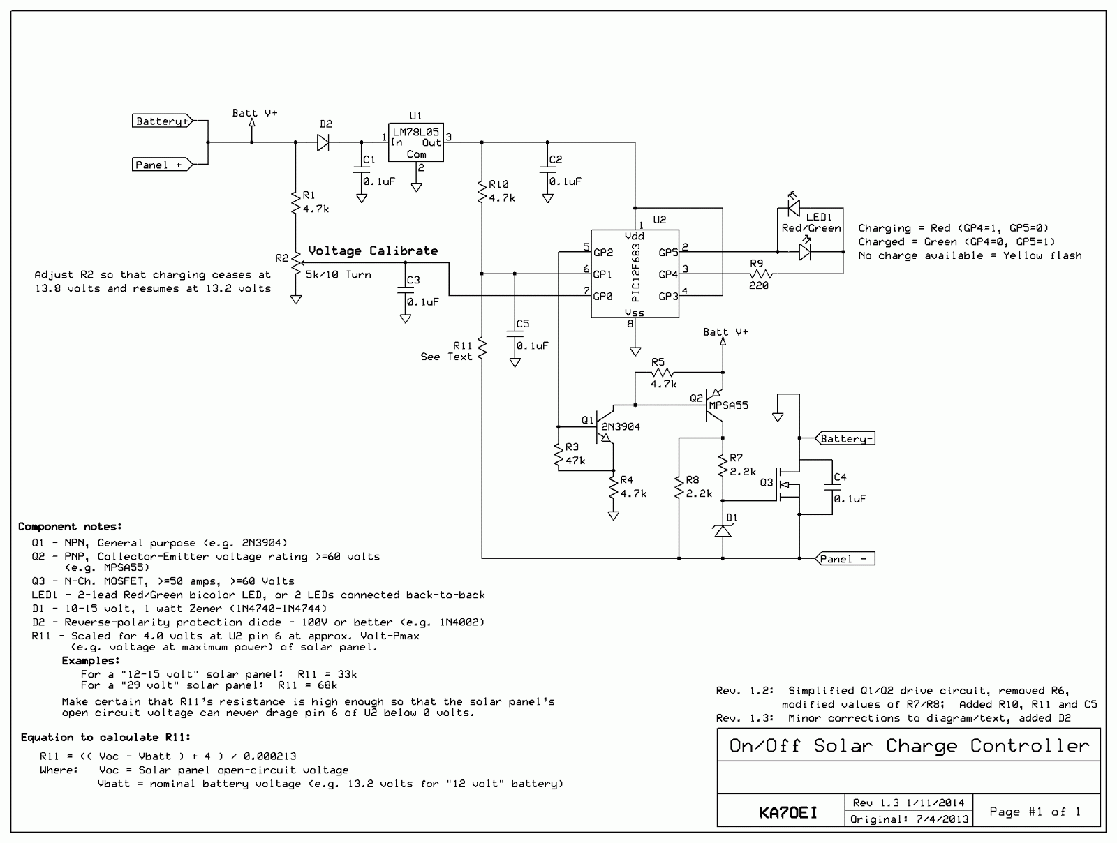
Figure 3.
Schematic diagram of the solar charge controller.  The circuit shown is intended for
"12 volt" (6-cell) lead-acid batteries.
It can be constructed using the PIC12F675 instead - see notes, below.
See notes and text for additional details about this circuit and its use.
Click on the image for a larger version.

So, there you have it, a very simple charge controller!

The .HEX files for programming a processor yourself:

Two .HEX files have been produced:  One for the PIC12F683 as described in the text, and another using the PIC12F675.  These files are NOT interchangeable or likely to be appropriate for other devices.

For the .HEX files, go to the page indicated by the link, below:
  
Web page with .HEX files for solar charge controller  (link)

If you cannot program a processor yourself and are interested in obtaining one, contact me.

Additional comments:

How it's connected to the battery:

As can be seen in Figure 1 large alligator clips are used to connect the battery.  Because the FET switch is in the negative lead, the positive terminal of the battery and the positive terminal of the solar panel are connected together at the battery.  It is recommended that short, heavy leads connect this unit directly to the battery to maximize charge efficiency and to best allow the controller itself to measure the battery voltage:  Long, skinny leads would cause a voltage drop, making the unit "think" that the battery was more-fully charged than it actually was.

A few warnings about the battery connection:

Because there is not extensive protection against high or reverse-applied voltages it is recommended that one connect the charge controller to the battery and then connect the solar panel, and when you are done, do the reverse - disconnect the solar panel then disconnect the battery.

Another extremely important point:  Make certain that the device being powered by the battery is firmly connected to the battery!

Because this device could put the full solar panel voltage across the terminals (in this case, 39 volts) a 12 volt device could be destroyed immediately by over voltage!  If you are using a battery that is in any sort of reasonable condition, this should never happen, but if your battery connections were loose - say, you had alligator clips from the device being powered connected to the battery and you had alligator clips from the charger connected to those clips - and the first set were to accidentally fall off, you could destroy your devices.

It is for this reason that you should always use the "permanent" connections to the battery to connect your devices (e.g. the battery posts.) so that you cannot accidentally have a connection to the solar panel without having the battery in the circuit.

Also, there's no "high-voltage" disconnect to protect the battery and the connected devices should the charge controller accidentally get "stuck" (due to the FET being damaged by lightning, for example) in the "on" state and continually applying current to the battery.  If this were to happen it is likely that the battery could be destroyed by gross over charging and the devices attached to it may be damaged as well.  In this circuit, the FET is reasonably well-protected against such things, certainly not against a very nearby or direct hit!


Explanation of the voltage thresholds:

In software, the battery is connected if its voltage drops below 13.2 volts and is disconnected if the voltage is higher than 13.8 volts:  In between these two voltages, the state is undetermined:  If the voltage had been below 13.2 volts, the panel will be connected (to charge the battery) but if the voltage had been above 13.8 volts, the panel will be disconnected.  Generally speaking, the panel will be connected as soon as the voltage is applied since it is unlikely that a battery that had been sitting for more than a few hours and not connected to a charger as its voltage will likely be well below 13.2 volts.

One could also use this same circuit for charging 6 volt and 24 volt systems as the ratio of the two voltages (on and off) would be correct for lead-acid batteries in this situations, too.  To do this, one may have to select an appropriate value for R1 as well as take into consideration the fact that U1, the voltage regulator, may not operate properly.

For example, at 6 volts unless a low-dropout regulator were used, or one used a different regulator to operate U2 at a lower voltage - say, 3.3-4 volts.  For 24 volts it may be wise to use a regulator that can withstand high voltages (>30 volts) for U1 or put in series with it a 10-15 volt Zener diode, taking care to leave the "top" end of R1 at the battery potential.   If you do change the voltage a which the PIC operates, you'll need to take into account that the voltage scaling resistors (R1/R2 for the battery voltage and R10/R11 used for monitoring the solar panel's open circuit voltage) are appropriately adjusted.

For other types of batteries (e.g. lithium-ion, NiCd or NiMH) this same sort of scheme could also be used, but very different charge-control schemes and voltage thresholds would have to be used to do this safely and this would imply a modification of the code.  Especially if you have several different types of battery chemistries, you may be better off having a small-ish lead-acid 12 volt battery to which these other chargers are connected to function as a low impedance "ballast".

In other words:  Do not use this circuit for any battery types other than lead-acid!

Why switch the panel in/out via its negative lead?

For this design I decided to put the power switching transistor in the negative lead of the solar panel rather than the positive lead and the reason for this is simple:  It was easier to do!

To have put it in the positive lead would have required one of two things:
  • The generation of a "boost" voltage.  I could have used an N-channel FET between the solar panel positive lead and and the battery's positive lead, but I would have trouble driving it.  The reason for this is that in order to turn on an N-channel FET fully, I would need to apply a gate voltage that would be at least 5-10 volts higher than the battery voltage.  Unfortunately, we cannot use the higher open-circuit solar panel voltage for this because if the FET were turned fully on, our solar panel V+ voltage would be the same as the battery V+ voltage.  In order to make this work we'd need to have a circuit that would generate a voltage that was higher than the positive battery voltage.
  • The use of a complementary device.  I could have used an opposite-polarity device such as a P-Channel power FET.  By doing so I could have "pulled down" on the gate/base and turned on the transistor, but there's a problem:  P-Channel FETs are harder to find, a bit more expensive, and typically have higher "ON" resistance than their N-Channel counterparts.  In other words, you can more easily and cheaply find N-channel FETs.
Why use a FET instead of a bipolar transistor in the first place?  Power FETs have the nice property that if you elevate the gate potential far enough "above" the source potential, they essentially turn into a low-loss "on" switch without requiring any drive current.  A bipolar power transistor, on the other hand, would require 1-5 percent (or more!) of the total device current being drawn through its base lead to make it fully conduct, and it would still drop more voltage across it and generate more heat than a FET.

Again, by switching the negative lead of the solar panel I could use a standard N-Channel FET:  Since the source lead of that FET would be pulled down and "away" from the +12 volt terminal of the battery (even to a potential that is negative with respect to the battery minus lead) by the solar panel - and since the PNP driving it was at the battery + potential, we already had a ready-made source of drive voltage for it.

How the circuit works:

U1, a 78LO5 3-terminal voltage regulator supplies a clean source of 5 volts for the microcontroller - and also serves as the voltage reference to determine the charge state of the battery.  The raw battery voltage is scaled first with R1 and then with potentiometer R2, the latter being adjustable so that the "on" and "off" thresholds for charging can be calibrated.

If U2, the PIC12F683 (or PIC12F675) microcontroller sees that the voltage is too low (nominally below 13.2 volts) its sets pin 5 (GP2) high which turns on NPN transistor Q1 which, in turn, pulls "down" on the base of PNP transistor, Q2 to turn it on.  Resistor R4 limits the base current in both Q1 and Q2 while R3 guarantees that if U2's output is in a high-impedance state (such as during startup) that Q1 is turned off by default:  R5 performs a similar function for Q2, respectively as well as speeding up the rate at which it can be turned "off".

When Q2 is turned on, approximately "Batt+" volts (nominally the battery voltage - in the 12-13 volt area) appears at its collector which pulls up on the junction of R7 and R8 which, if the sun is shining, was already at a voltage that is equal to the open-circuit output voltage of the solar panel minus the battery's present terminal voltage:  In the case of the solar panels chosen, the open-circuit, full-sun voltage is around 39 volts so if the battery is at 12.5 volts, the drain of Q3 will have been at -26.5 volts with respect to "ground" - the negative terminal of the battery, or close to the full 39 volts of the solar panel's open circuit voltage.

Pulling the gate of Q3 "upwards" (e.g. making it positive) will turn it on, connecting the negative lead of the solar panel to the negative battery lead.  At this point the gate voltage will drop to about 12-13 volts, but this is sufficient to keep the device chosen fully turned on.  Because the gate-source voltage could conceivably exceed 20 volts or so - the (typical) maximum rating for such a device - at the instant that we turn it on Zener diode D1 in conjunction with R7 form a simple shunt regulator to limit its maximum voltage to a safe level.

Once the voltage rises above 13.8 volts U2, the controller, sets Pin 5 low which turns off Q1 and Q2 and allows R6 to pull Q3's gate voltage down to its source voltage and turn it off, disconnecting the solar panel from the battery.  C4, a 0.1uF capacitor, is placed across the FET so that any "ringing" or transients generated by the FET's being turned on and off are suppressed as well as providing a degree of RFI and static protection.

For this circuit to work properly, Q2 must be rated for the voltages that it will encounter so an MPSA55 was used which has a rating of 60 volts.  Q3 must also be rated for the expected voltage, low "on" resistance and several times the maximum current expected from the panel so a 100 volt, 50+ amp device was used to provide plenty of margin.

The reason for the use of both Q1 and Q2 is so that one can apply the battery voltage to the gate of Q3 when it is "on" to make certain that its resistance (and loss) is as low as possible:  Were Q2 driven directly by U2, we could only attach its emitter to the +5 volt supply and it was turned on, only about 5 volts could have been applied to Q3's gate which, for "normal" N-channel power FETs, may not be enough to drive it into full conduction and minimize its ON resistance.

In looking at Figure 1 and Figure 2 you may note that there is no obvious heat sink on Q3.  In actual operation, with 5-9 amps of current, it ran only very slightly warm but there was plenty of convection coupling (air cooling) as well as heat conduction via the heavy wire (#10-#12 AWG) that was soldered directly to the tab of Q3, its Drain lead which, in turn, connects to the negative lead of the battery.

Added later (after the pictures were taken) is the circuit consisting of R10, R11 and C5.  Forming a voltage divider, this allows the measurement of the voltage across the solar panel when Q3 is turned OFF to determine if there is any usable light falling on the solar panel.  If there is not, the computer will keep the solar panel disconnected and occasionally flash LED1 yellow to indicate that there's presently no power available from the solar panel.  To do make this determination while it is charging (e.g. the LED is red) the panel will occasionally be disconnected for a very brief moment to measure the voltage across the panel.  Of course, if it is not charging (LED is green) it doesn't need to disconnect the solar panel at all to make this reading.

If the panel is being illuminated and Q3 is off, the "Panel -" voltage will go negative with respect to the PIC's ground and via R11, pull U2, pin 6 down from the +5 volt supply   If the voltage on pin 6 of U2 is below about 4.0 volts when the panel is disconnected via Q3 - which indicates that the panel is capable of providing at least some charging current - we know that it is worth attempting to charge the panel.  If the voltage is higher than 4.0 volts when the panel is disconnected via Q3 we can safely assume that there is too little light to bother with and this will put the controller in a mode where it will not attempt to charge the panel and cause the LED to flash yellow every two seconds or so.  (If you have two separate LEDs, both will flash at the same time.)

Calculating the value of R11:

Note that the value of R11 should be chosen for the type of panel to be used.  Nominally, the voltage at pin 6 of U2 should be 4 volts (or lower) at the voltage at which the panel outputs maximum power (this is usually listed in the specs) and R11 should be high enough that at when the panel is open-circuit in full sun, that maximum voltage (often noted as "Voc" in the specs) is not high enough to try to drag pin 6 below ground.

On the diagram are two values shown:  33k for a panel typically used to charge 12 volt batteries directly (e.g. maximum power at around 14-17 volts, 24 volts open-circuit, maximum) and 68k for the panels that we used here (29 volts at maximum power, 39 volts or so open-circuit.)  On the diagram the formula:

R11 = (( Voc - Vbatt ) + 4 ) / 0.000213

Is given.  Since the supply voltage is 5 volts - and we want 4 volts at Pin 6, we want 1 volt of drop across R10 which yields approximately 213 microamps as noted in the above equation.  Kirkhoff's law dictates that the same current must flow through R11 to obtain that same voltage drop across R10 so we add 4 volts to the difference between our expected solar panel open-circuit voltage and get about 31k:  33k is chosen since that is the nearest common resistor value, yielding a "low voltage cutoff" of about 16 volts open-circuit panel voltage.

The "Vbatt" term is one that we must approximate:  If we used precision, fixed resistors for R1/R2 we would know the precise divisor ratio and be able to calculate the battery voltage and subtract it from the open-circuit panel voltage - but since this circuit doesn't do that, we must pick R11 to suit our needs.  In general, if we assume Vbatt to be 13.2 volts, the charge-cutoff circuitry will work fine for a "12 volt" lead-acid battery regardless of its charge state - as long as it is above 6 volts or so since we must have at least enough battery voltage to power our PIC circuit.

Comments:
  • Charging a completely dead battery:  If you were to have this circuit connected to a completely dead battery, charging would never start since the PIC could not be powered from the battery.  Were this to happen - and the solar panel was producing power - one would temporarily connect the Panel - and the Battery - connections together to provide a "bootstrap" charge to the battery.  It may take several minutes for the battery to have enough charge voltage to keep the circuit operational - and this would be true only if the battery was good.  A few warnings if you do this:  Disconnect EVERYTHING ELSE from the battery as it may be bad, and the full panel voltage may appear across the battery if you connect it directly to the panel.  If you do connect the panel directly to the battery in this way, do not walk away - keep monitoring the voltage until it reaches the low-mid 12 volt area.  Finally, be careful when connecting/disconnecting battery connections as sparks may cause hydrogen/oxygen gas explosions.
  • If you were to use a 29 volt panel to charge a 12 volt battery (read below about the efficiency losses in doing so!) there would be no harm in keeping the battery connected if that panel's open circuit were allowed to drop to 16 volts or so - as might happen at dawn/dusk or if the panel were partially shaded or damaged.  At 29 volts, however, the voltage a pin 6 will attempt to go negative, but diodes within U2 will prevent it from going much below -0.6 volts.  While in some cases this excursion beyond the supply rails can cause unexpected effects on the PIC's A/D input MUX and affect other A/D channels, that did not seem to occur in the prototype and it functioned fine - but your results may differ.
  • When in "Inhibit charge" mode (e.g. open-circuit panel voltage too low and charging is discontinued) the prototype, using a 78L05, consumed about 5.5 mA average battery current.  Much of this is the quiescent current of the voltage regulator, but some of it is also the LED occasionally flashing yellow to indicate that it is in a "not charging" mode.  When charging, the circuit will consume around 25 mA, most of this being drawn by the LED and the circuitry that turns on Q3.

Set-up notes:

Setting this circuit up is slightly tricky, but not difficult if instructions are followed.
  • As noted above, please be aware of the hazards associated with high voltage and/or current!
  • Preset R2 to the middle of its range.
  • Connect a variable voltage power supply across the Battery (+) and Battery (-) terminals and set it for 13.20 volts.
  • When first connected, the LED will cycle Green-Red-Yellow if you are using a dual-color LED.  It may then be either a solid color, of flashing.  If it cycles RED-Green-Yellow the LED's leads are reversed!  If you used separate LEDs instead of a single, dual-color LED, both will be on instead of displaying yellow.
  • Make sure that the LED(s) is/are properly connected and/or identified via the power-up color sequence.
    • The colors represent:
      • Red = charging
      • Green = not charging
      • Yellow (brief flash) = Charging voltage not available.
  • With the power supply connected across Battery (+) and Battery (-) set to precisely 13.2 volts, adjust R2 so that the voltage on its wiper (which is also connected to Pin 7 of U2) is 51.6% of the 5 volt power supply's voltage.  If the power supply were precisely 5.0 volts, this would be 2.58 volts.  It is normal for the output of the 78L05 regulator to be between 4.9 and 5.1 volts due to manufacturing tolerances:  It is recommended that you measure it precisely and calculate the 51.6% voltage.  This sets the charge cut-in threshold voltage.
  • If you set the power supply voltage to precisely 13.8 volts, the voltage measured on U2 pin 7 would be 54.0% of the PIC's 5 volt supply voltage, or 2.70 volts.  This is the charge cut-out threshold voltage.
Operation notes:
  • Using the value specified for R11 (33k), if the battery voltage is 13.2 volts and the open-circuit solar panel voltage is below 16 volts, the unit will determine that there is not enough energy from the panel to effectively charge it and in this mode, the LED will be mostly dark, flashing yellow every 2 seconds.  (If you used separate LEDs, they would both light up during the flash.)  Every 5 seconds during charging, the unit will open Q3 and briefly measure the voltage - a process that takes less than 100 milliseconds.
  • If the open-circuit panel voltage is above 16 volts, normal charging will occur with Q3 being closed.  If the battery is discharged and its terminal voltage is below 13.2 volts, the LED will glow red.
  • Once the battery voltage has exceeded 13.8 volts, charging will be stopped, Q3 will be opened and the LED will glow green.
  • Once a battery has achieved full charge, it is normal for the LED to be mostly green, occasionally flashing red - perhaps as often as twice per second.  It is also normal for the voltage to stabilize near 13.2 volts and slowly move upwards over a period of hours or days:  At 13.2 volts, a 12 volt lead-acid battery is "mostly" charged.  Because this controller can only turn charging "on" or "off", it is rather difficult to precisely obtain a charge voltage.
If lead-acid batteries are used other than 12 volt lead-acid, the above steps would be modified accordingly, but note the following:
  • The input to U1, the 78L05, must be at least 6.5 volts for the circuit to work properly.
  • U1 cannot tolerate much above 30 volts, so accommodations must be made if this can happen to protect it.
  • Keep in mind the voltage ratings of Q2 and Q3:  The rating of each should be at least the battery voltage plus the open-circuit panel voltage for a good safety margin.
  • If a different voltage panel is used you will need to properly calculate the value of R11 as noted elsewhere in this text.
  • R2 would be adjusted to 51.6% of the 5 volt supply to set the threshold for the battery voltage  below which charging would be started.  Again, the termination of the charge occurs at 54.0% of the 5 volt supply.  If the battery voltage is increased, it may be convenient to increase the value of R1 appropriately to better-scale the threshold voltages within R2's adjustment span.

"No diode in series with the panel?!?"

It should be noted that there's no "reverse polarity" diode in shown on the diagram as being in series with the controller to prevent the battery's charge from being applied to the panel when the sun is absent.  As it happens, almost all modern, manufactured panels have these diodes built in, anyway - but it would be a good idea to closely check the  panel's specifications.

If, when you connect your panel (shaded from the sun, or in the dark) across your battery and you see more than a few 10's of milliamps flowing into the panel then you might consider adding a series diode to prevent this.

More Comments:
  • While an "MPPT" controller (see the very last section of this article, "By the way, what's an MPPT charge controller?" below, for an explanation) would have been nice, this just wasn't going to happen on such short notice so I threw together a simple "on/off" voltage controller to allow current to be safely thrown at the battery without worrying too much about overcharging it.
  • Charging a battery from a solar panel with a voltage that far exceeds the requirements is very inefficient.  As noted above, if one used a normal "12 volt" panel (those with an open-circuit voltage in the 17-22 volt area) this short of charging is much more efficient.
  • If you build/use this controller for yourself, remember that there are no guarantees that this circuit is either effective or safe.  YOU are responsible for becoming familiar with and implementing the appropriate safety measures and dealing with hazards associated with high voltages and/or currents.
  • Not shown in the diagrams/pictures are necessary fuses and other protection that one must include in a practical installation.


By the way, what's an "MPPT" charge controller?

The charge controller described here simply connect the solar panel to the battery to charge and then disconnects it when the battery has achieved full charge - essentially similar to the "old-fashioned" way solar panel chargers used to work.  Because solar panels act as a source of current, it doesn't really care if its output is shorted out or left open.

Given that our hypothetical solar panel that will output 9 amps at 29 volts we can see that at that voltage we could extract (9 amps * 29 volts =) 261 watts from it, but if we were to short out the panel we would get zero watts (e.g. 0 volts * 9 amps = 0 watts.)

With this on/off switch connecting/disconnecting our battery, we will obviously get 9 amps into the battery, but if the battery were at 13 volts and charging, that would only be (9 amps * 13 volts =) 117 watts of power - this, from a panel that could provide much more than this at a higher voltage.

Clearly we are leaving 144 watts "on the table" somewhere, so how would we make use of it?  One way would have been to charge two 12 volt batteries in series (for 24 volts) which would have yielded 234 watts (e.g. 9 amps * 26 volts assuming 13 volts per battery = 234 watts).  This is much better, but our equipment doesn't actually run on 24 volts and it would be awkward to drag along two 12 volt batteries, anyway.

The way around this is to have an intelligent switching voltage converter.

The way this works is that it has a computer (digital or analog) that will figure out, on the fly, how much current it can pull from the solar panel and automatically calculate the amount of power being pulled at the same time by doing the standards "volts*amps" calculation.


One way to do this is to slightly adjust the switching voltage converter - a circuit that can efficiently convert a higher voltage at lower amperage to a lower voltage at a higher amperage - so that it tries to output a little more current which, in turn, would cause the input to attempt to pull a little more current from the solar panel.  When it does this it does the "Volts * Amps = Watts" calculation of power  and if, when it increased the current being pulled from the panel, it actually did get more power, it would try to pull still more current from the panel, incrementally - but if less power was available, it would decrease the current incrementally to rediscover the optimal condition.  This method is called "Perturb and Disturb" as it constantly "hunts" to dynamically determine the optimal power available from the panel.

If, for some reason, the "volts * amps = watts" calculation showed that there was actually less power available when we attempted to increase the draw from the solar panel by trying to pull too much current and/or the solar panel's output has dropped due to cloudiness, setting sun and/or shading, it would incrementally back off on how much power it tried to pull - and keep doing so until it got to the point at which it, again, got to the maximum output from the panel.

In doing this slight incremental up/down and "feeling" to see if there is more power available from the solar panel, we would be able to extract the maximum amount of power from the panel based on the conditions at that instant.  This type of controller is called an "MPPT" or "Maximum Power Point Tracking" - so called because it constantly adjust itself and tracks the conditions of the charge source (the solar panel) to determine the maximum power that can be extracted from the solar panel and delivered to the load.

[End]

This page stolen from ka7oei.blogspot.com

Tuesday, June 18, 2013

Resurrecting a Nikon S8100 from "Lens Error" death (that is, S8100 "Lens Error" fix)

Nikon S8100 "Lens Error" fix

A friend of mine came back from vacation and handed me his P&S (which supposedly stands for "Point and Shoot") camera - a Nikon S8100.

Ostensibly a nice, compact camera, it seems to have earned a bit of a reputation - namely that if dropped from a short distance (say, a kitchen table) onto the floor (a carpeted one, for example) while in its padded, protective case, it will henceforth turn on with a cryptic and useless "Lens Error" diagnostic  It will then refuse to turn off with the power button, but turn itself off after a while.

Unlike other point-and-shoot cameras that I have seen with problems with their retractable lenses, this one DID NOT make any noise at all - other than a musical "bling" - when it was powered up:  No clicking, whirring, or anything else to indicate that the lens was even trying to do something.  This was highly suspicious and I guessed that a connection might have dislodged preventing the motor from operating - but I wasn't sure.

A quick Google search revealed many hundreds of comments about other owners having suffered this issue - many within 3-6 months of buying the camera new and lots of useless information from a site called "FixYa".  Apparently, Nikon originally did offer in-warranty repair, but the anecdotal evidence would seem to indicate that they soon ceased doing so, citing what many posters referred to as "normal wear and tear" as "out-of-warranty" damage and socking them with a bill that was typically around $110 U.S.  - roughly half of the camera's original purchase price!

So it was with this camera, presented to me in June 2013 - well out of warranty.  Unfortunately, no-one that I could find on the web offered a clue as to what caused this problem, much less a solution to it.

Until now.

IMPORTANT:

Before you go any further, please read the following - and then read it again:
  • NO, I will not fix your camera!  That's just not a business that I want to get in to at this time.
  • NO, I will not fix your camera!  (I just thought that I'd say it twice!)
  • The details on this page apply only to the S8100.  This same problem may occur on other, similar models, but I don't know that for certain.  Having said that, this is the fifth camera that I have "repaired" (all of them different makes and models) where the "failure" was just an internal cable coming loose, so I know that it's a common problem.
  • I do not own an S8100 - I just fixed it for a friend and gave it back, so I don't have it around to look at!
  • Unless you are familiar with the delicate work on miniature electronics, you probably can't fix it!
  • DO NOT attempt this without at least some knowledge of electronics and mechanical systems.  Many of the parts are fragile and tiny and need to be handled appropriately.
  • This camera contains a flash capacitor that may have hundreds of volts on it.  If you accidentally touch this, you will, at the very least, receive a very unpleasant shock.  At worst, this discharge through your skin can destroy other camera electronicsIt is also possible - although unlikely - that such a discharge can stop your heart and kill you!
This potential solution describes ONLY where the camera exhibits the following traits:
  1. The lens is fully retracted (e.g. IN).  If your lens is stuck while extended, this probably doesn't apply!  Having said that, you may have nothing to lose by trying this.
  2. When you turn the camera on, it does NOT make any mechanical noises such as motors whirring, clicking, whining.  The ONLY noise that it makes is a musical "bling" from the speaker.  If you hear ANY motors whirring and clicking, you may not be experiencing the same problem.
  3. It says just "Lens Error" with an exclamation point on a mostly white screen.  Nothing else.
  4. It will not turn off with the power button, but it will eventually turn off by itself.
  5. With the camera, you cannot access the images stored on the memory card to review them.  (You could always remove the card and read it directly via a card reader, of course!)
Having said all of the above, let's get on with it.

Disassembly:

First, remove the battery and memory card!

What you will need:
  • You will need to read - and re-read this entire procedure before starting.
  • A clean work area that is well-lit.
  • A magnifier and/or a set of strong reading glasses.
  • A pen/pencil and paper to make notes and drawings of how things came apart - and how they go together.  Taking pictures at each step wouldn't be a bad idea, either!
  • Small containers to hold the screws and various camera parts.  A container used for holding eggs with pieces of paper describing where the individual parts come may work for you.  (Just make sure there aren't holes in the bottom of the sections!)
  • A thin, plastic blade to pry pieces apart.  If you are really careful not to cut/short anything, a thin metal blade can also work, but you are more likely to break something this way!  (You'll notice in the pictures that I used a metal blade - but I've done this before...)
  • A very small "Philips" type screwdriver:  I used a size "000" of the sort that might be found in a set of Jeweler's tools that I bought some years ago from Harbor Freight.
  • A pair of tweezers.
  • Patience, a steady hand, and some experience with successfully having done a similar thing before.
Figure 1:
Bottom of the camera showing the 7 screws.
Click on the image for a larger version.
 
There are six different types of screws holding the portions of the camera together that need to be removed and I arbitrarily labeled them types "A" through "F".  All of these screws should be removed as noted.
  • Bottom cover:  Four black, flat-head screws of "medium" length around the tripod mount - I called these type "A".
  • Bottom cover:  Three black, flat-head screws that are very short - two to the left of the battery door (bottom-up, lens facing you) and one by the upper-right corner of the battery door.  I called these screws type"B".
  • Left side:  (The side without the HDMI connector/wrist strap).  Two "B" type (short, black) screws.
  • Right side:  (The side WITH the HDMI connector/wrist strap).  One "B" type (short black) screw near the bottom of the camera, and a long black screw (what I call type "C") UNDER the HDMI cover.
Remove the wrist strap (if attached) and very carefully remove the panel on that side while carefully noting how the HDMI cover attaches in its slot!  Under this panel you'll notice 5 screws of two different types:
  • Two short silver-colored flat-head screws that hold on the wrist strap.  Note carefully how this mounts and draw a picture if you have to!  I called these type "D" screws.
  •  Two more "D" type screws holding edge of the black plastic of the camera's rear panel, one on each side of where the wrist strap was connected.
  • With the camera on end and the lens facing you, there is another screw in the lower-right corner under the HDMI connector.  It is a long-ish silver screw with a machine head.  I called these type "E" screws.
At this point, you can very carefully snap off the rear panel.  The back of the camera which includes the LCD (display) bezel (but not the display itself!) and the knobs stay with the camera and not the bezel while the four buttons on the back (the one with the red arrow, the "play" button, menu and "trash can") stay with the bezel.

You can also carefully pop off the panel on the other (left) side of the camera if you wish - but it is not necessary although it may make it easier to put the back panel on again, later.

Note:

There are a number of plastic catches/tabs that hold the rear panel in place and removing it is a bit tricky.  I would suggest the use of a thin plastic blade to press between the gaps of the connectors to try to release the catches.  Do not force the panel to come off!

This is a bit of a pain and other than be patient and observant, I don't really have any other advice on how to remove it except to assure you that all of the screws holding it in place have been removed by this point!

Once you have removed the rear cover/bezel:

Removing the panel with the buttons and rear-panel wheel:

Once you have successfully removed the camera's back, place it lens-down, preferably on a clean, soft, lint-free cloth, with the bottom facing you.  In the upper-right corner, tucked almost underneath the metal panel with the rear-panel knob and buttons, you'll see a screw (type "E") that needs to be removed - and you'll probably need tweezers to remove it when it is loose.  See Figure 2, below.
Figure 2:
The screwdriver (upper-right) points at the screw that holds the wheel/button assembly in place.
This panel slides out to the right.  You may need to push in on the panel slightly to release it.
Click on the image for a larger version.

Now, the panel with the four buttons and the rear-panel knob needs to come out.  Pressing down on it slightly, slide it to the right (away from the LCD) to allow it to clear the one tab at the top and the two at the bottom, noticing carefully how it went in.

Be careful to not pull on the flat cable attached to this panel.


Figure 3:
The screwdriver is pointing at the "upper" tab holding the panel in place and two other tabs hold the
bottom edge.  Once the screw is removed, this panel slides out of position - but be careful to with
the cable attached to it!
Click on the image for a larger version.


Now, to remove the cable from the connector on the circuit board, using your fingernail to flip up the black plastic cover on the connector.  To do this, you slide your fingernail under the same side that the cable enters and when it flips up on its hinge.  It is only after flipping up this door that you will be able to easily remove the cable, noting carefully how far it went into the connector!

Note:  The on-board connectors to which the cable attaches are a bit tricky.  These particular connectors have a black (or very dark brown) "door" that flips up, the hinge being on the side opposite where the cable comes in or, in other words, it is the side where the cable comes in that flips up.

You will need to remove two cables with this type of connector:  The fairly small one coming from the control panel, above, and the much larger one connecting the LCD.  You are cautioned to lift up from the center of the flip-up portion with only a fairly soft item - such as your fingernail.  If you break this door off you will not be able to secure this cable into position and your camera will probably not be usable! 

Removing the main LCD panel:

Comment:  You may be able to complete the repair without having to disconnect the LCD panel from its connector, but rather carefully laying it over the side of the camera with the HDMI connector.  Remember that this cable is extremely fragile and can be easily torn or partially pulled out of the connector.

Removing the LCD panel from its connector - and getting it back in again - is probably the trickiest part of this procedure, so pay very close attention.
 
Figure 4:
LCD cables.  The black flip-up portion (which is hard to see) locks the large cable into place.
The smaller cable for the LCD's backlight may be seen to the left:  It just slides in/out of place.
Click on the image for a larger version.

At this point the LCD is only held in by snap-in points around the edges.  Using a thin plastic blade, work your way around the LCD and work it free.  At this point all I can suggest is that you be observant and carefully note where it is hanging up if it doesn't come free.

Once you have freed the LCD, take a close look at its large cable and you'll see that it, too, has a "flip-up" connector - a sort of black "door".  Using your fingernail, flip this up and you should be able to flip it up and free it.

Note:  Pay very close attention to how far the large LCD cable went into the connector.  Re-inserting this cable is rather tricky and is very critical!

For the smaller cable, it is held in place only by friction so carefully pull it straight out of the connector - but note how far in it slides.

Removing the LCD mount:

Now that you have removed the LCD (or not - see the comment above) you are left with the LCD mount and metal cover/RFI shielding for the imager.  Under where the LCD was sitting you'll see four screws.  With the lens facing down and the bottom of the camera facing you:
  • The two upper screws and the lower-left are what I called type "F" - longer that "E" and silver with a machine head.
  • The lower-right screw is a type "E".
Figure 5:
This LED, which is indicates that the flash is fully charged and ready, must be "un-stuck" from the
metal frame and moved out of the way.  Don't forget to put it back later!
You can see from the picture that I used a metal blade, but I'd recommend that you use a plastic
blade unless you are really careful.
Click on the image for a larger version.

Now locate where the upper-right corner of the LCD would have been and you'll notice an LED on a small, flexible cable that is stuck to the metal with double-sided sticky tape.  Carefully pull this off by sliding a small, plastic blade under it and move it aside, noting its exact placement.  See Figure 5.

At this point, the metal frame that held the LCD is fairly loose, but note carefully that parts of it wrap around each side of the camera, held in by some of the side-panel screws.  Remember how these tabs are arranged and where they go!

Now, while pulling up on the metal mount that held the LCD you'll see that it is now held in place with two pieces of copper foil tape.  Using a thin, plastic blade, reach between the metal and the rest of the camera and use that to pull and release the tape.  Once you have managed that, the metal frame will come out easily.

Figure 6:
The LCD mounting frame/shield with the 4 screws already removed.  The knife is pointing at one of the
two pieces of self-adhesive copper foil.  Just above it is another piece that must be carefully detached
as the frame/shield is removed.  Again, you see that I used a metal blade, but I'd recommend a plastic
blade unless you are really careful!
Click on the image for a larger version.
At this point you are looking at the backside of the lens and the imager.  With the camera facing down and the bottom facing you, look at the connector coming off the lens assembly at about the 2-o'clock position, being pointed at by the red pen in Figure 7,  and you'll observe that it is probably loose, if not now floating in space.

This is the problem!
 
Figure 7:
The pen is pointing at the connector that comes loose and causes the "Lens Error" problem.
The connector just below it carries the image (picture) signals and if this is loose, one can
experience image quality issues.  Both connectors should be properly re-seated!
Click on the image for a larger version.

At this point I would recommend popping off this connector and the one next to ("below") it (at the 3-o'clock position) - which also comes from the lens body and contains the imager's signals - and firmly, but carefully, re-seating it.

Note:

It may be that reports of degrading image quality are the result of the other connector - the one below the one pointed to in Figure 7 - coming loose.
 

What seems to be the problem is that while there is some foam on the backside of this connector to hold it in place between the LCD support frame, there seems to be a slight "bias" and the connector appears to be being compressed with this foam at a slight angle.  When the camera is jarred - say, by falling a short distance onto a padded surface while in its protective case (or something worse!) this connector tends to pop off!

It may be that one could put a piece of thin plastic in there to hold it in position, or perhaps, a dab of tacky adhesive or small bit of RTV ("silicone" - the sort that does not smell like vinegar!) - and if you do, that's up to you - just make sure that it doesn't get anywhere it shouldn't (such as inside the connector!) or on anything else and that it has cured/dried before reassembling the camera.

Reassembly:

I hate it when I read it elsewhere, but I'll say it now:  Reassembly is the reverse of disassembly!

In a nutshell:
  • Make sure that the connectors from the lens assembly are firmly and properly seated - and check other connectors while you are at it!
  • Slide the metal LCD mount back into place, noting the proper placement of the "fingers" that extend along the sides of the camera.
  • While installing the metal LCD mount, make sure the LED that you moved out of the way (the one picture in Figure 5) is clear and isn't being sandwiched under the metal mount.
  • Reinstall the 3 "F" type screws (top, lower-left) and the 1 "E" type screw (lower-right).
  • Put the adhesive-mounted LED (the one in Figure 5) back where it had been (just beyond the upper-right corner of the LCD.)
  • Make sure that the pieces of copper foil are again pressed down on to where they were originally stuck.
Reinstalling the LCD and its cable:

If you haven't dealt with this type connector before it can be really tricky to get right!  You'll recall that to remove the cable, you had to flip up the plastic lid on the wide LCD cable and simply pull the small cable out of the compression-fitting connector.

With the LCD facing down, toward the table and its cables going to the left of the display (e.g. flipped over to the right from its normal mounting position) you'll see that you can arrange the large cable so that it more-easily fits in the connector.  You must have the lid/door on this connector flipped open at this point!

You can now align the cable so that it slides into the connector - but this is quite tricky.  One thing that is not obvious to the casual observer is that the very end of the cable must slide partway underneath the hinge of the flip-up door in order for it to properly make contact - but it only moves about 1-1.5 millimeters when it does this!

Once you have inserted the cable, use your fingernail or a piece of soft plastic (or a pencil eraser) to carefully close the door.  If you have done it properly, the cable should look perfectly straight and as you shut the door, you should see/feel it compress against the flat cable as it locks it into place!

Assuming that you have done this, use a pair of plastic or bamboo tweezers and carefully slide the small connector - used for the LCD's backlight - into place.  If you are dextrous - or have very small fingers - you may be able to do it that way as well.

Once the connectors are installed, you can now snap the LCD back into position in its metal frame.

Testing the LCD before final assembly:

At this point - before you go much farther - it would be a very good idea to verify that you have, in fact, installed the LCD connector properly, even if you did not disconnect the LCD's cable(s).  Insert the battery (but do not install a memory card) and power up the camera while holding it in your hands, off the workbench so that the lens can extend.

If all goes well, the lens will extend and your LCD will display an image or menu.

Whether the lens does/doesn't extend and/or you do or do not see an image on the LCD, turn the camera back off (to retract the lens) and remove the battery.


If the lens doesn't extend:

All I can suggest is that you go back and make sure that the connectors depicted in Figure 7 are firmly seated!

If you don't see an image on the LCD:

If you see the LCD light up (e.g. the backlight turns on) but there is no image or menu displayed, you probably didn't get the LCD's large cable properly seated in the connector.  You don't have to remove the LCD from its mount to attempt to re-seat the connector, and having it improperly seated probably won't damage anything - but it just won't work!  If the LCD's backlight did not turn on, make sure that the smaller cable is properly inserted.

If you experience a problem you'll have to try to re-seat the connector.  You may want to use small pieces of plastic or wood (toothpicks) to manipulate the large LCD cable so that it properly seats within the connector.

Remember:  Make sure that the "door" on the connector is flipped open and that the edge of the cable slides just a little bit under the door's hinge!  The cable must be perfectly straight in order for it to fit and mate properly!

If you can't get it to work, you might want to set it aside and try again later - or have someone else try it.

In my opinion, this can be the trickiest part for someone who doesn't know exactly how these connectors go together!


Final reassembly:

Remember:  Remove any fingerprints from the surface of the LCD using a soft piece of cloth or lens tissue (but NOT a paper towel!) before reinstalling the rear cover panel/bezel.

Note:  At this point, the lens and the LCD are assumed to be working and you should have turned the camera off to retract the lens and also removed the battery!

Now, continue with the "reverse-disassembly."  The only tricky parts that I noted were:
  • The HDMI connector cover.  The tab of the HDMI cover goes in the slot on the plastic side trim piece.
  • The rear edge of the top cover.  I had a bit of difficulty getting the edges of the rear panel and the top cover to mate and snap together, but a bit of pushing on the joints successfully re-seated them.

If all goes well, your S8100 should be working again!


Note:

Please read, and then re-read the warnings and comments at the top of this page!  Again:
  • I won't/can't fix your camera!   If I did, I'd probably have to charge you as much as one would cost on the used market!
  • This is for the S8100 only!  Some of this advice may apply to other cameras, but I don't know!
  • Unless you are skilled at working on small electronics, you will probably not be able to do this repair!
  • This camera contains dangerous voltages that can result in damage, injury or even death!
  • If you do this, consider your camera to already be lost and that you aren't going to be successful.  That way, if it does work, you'll be happy but if not, you won't!
 You have been warned!
  
Best of luck!

As of July, 2014 when I write this addendum, my friend is still using this camera, regularly!

 Tags: 
  • Nikon S8100, Lens Error, Lens won't extend, Nikon S8100 Lens Error, Nikon S8100 Lens won't extend, lens won't move, Nikon Lens Error, lens doesn't make a noise, camera turns on with "lens error", camera chimes and says "lens error!"
 [End]

This page stolen from ka7oei.blogspot.com

Friday, June 7, 2013

Long-term observations of NiCd versus NiMH cells and how to make them last longer.

Nickle-Cadmium (NiCd) and Nickle-Metal Hydride (NiMH) cells are ubiquitous, but their behavior in typical consumer items is not at all well understood by most people.  Much of this is because one never thinks about what is powering that portable device until it stops working, but a lot of it has to do with confusing advice and misinformation about them and how they behave.

Another problem is that in long term, NiCd cells can have longer life spans than NiMH cells, but why is it that in so many applications people find that the NiMH cells outlast the NiCd cells that they used to use?

We'll answer that question along the way.

The economics and convenience of rechargeable cells:

Even if they don't last very long (in terms of years) rechargeable cells are almost always much less expensive to own and operate than their non-rechargeable Alkaline cousins, but there is a convenience factor involved:
  • You can probably get more run time (from many - but not all - devices) from a set of alkalines than you can from a single set of rechargeables.
  • When you put in a fresh set of alkalines, you have a pretty good idea how long that device will run.  Unless you pull rechargeables off the charger - and you know that they are good, you don't know before-hand how long the device will run.
  • A set of alkalines can sit around in the package, unopened, for several years and still be good.  Again, with rechargables you don't know their charge state for certain - particularly if you haven't used them for a while!
 Based on the above, one might be understandably wary about using rechargeable cells, but for many devices - such as portable power tools - there's really no option!

Alkaline Cells:  A comparison to NiCd and NiMH:

Other than the fact that they are rechargeable, what are the main differences between alkalines and NiCd/NiMH cells?  As it turns out, voltage isn't really an issue since modern devices will happily run at 1.2 volts per cell - the same as NiCd/NiMH and a half-discharged alkaline.

What about capacity?

A good-quality alkaline AA cell has a capacity of about 2.5-2.8 amp-hours.  Comparing an AA-size NiCd, its capacity will be in the area of 0.6-1.1 amp-hours and a NiMH will have a capacity of between 1.8 and 2.8 amp-hours, depending on the brand and specific type.  In general, the rechargeable cell will have less capacity than the equivalent sized alkaline, but why is it often the case that it runs an electronic device longer?

Internal resistance is the answer.  When fresh, the internal resistance of a good-quality AA alkaline cell is on the order of 0.15 ohms per cell, increasing to 0.3 ohms per cell when the it is 50% discharged and over an ohm when 80% discharged!  If your camera uses a battery of 4 cells in series that means that the total resistance of new cells (excluding resistance of battery contacts and wiring) is about 0.6 ohms, rising to 1.2 ohms when the battery is just 50% discharged - and it only gets worse (much worse!) as the it is further-depleted!

If the digital camera consumes, say, 800 milliamps (a reasonable amount when a flash is charging, a backlit display is operating, etc.) then cell resistance alone will dictate a voltage drop of 0.48 volts for a battery with new cells, and 0.96 volts or so for cells that are 50% discharged.

Again, this does not take into account other resistive losses - such as contacts and internal wiring - some of which can be significant!
 
For new cells in a 4 cell battery, this voltage will (optimistically - assuming a nominal 1.5 volt unloaded output) amount to about 5.5 volts under these conditions, dropping to about 4 volts when the cells are 50% discharged - a voltage that may be inadequate for operation of the camera.

There is yet another problem.  Often, cameras contain switching-type voltage converters.  While these are efficient in their energy conversion, they attempt, by their nature, to maintain a constant power output over a varying input voltage.  What this means is that, as the battery voltage drops, the current consumption will increase as the voltage converter attempts to maintain the constant voltage output - exacerbating the problem of already-low voltage and resistance.  This problem can get worse when the camera's load changes because of a charging flash, a backlit display being illuminated, or the camera's CPU pulling more current when processing the image and saving it to memory.

In other words, the cells may be, say, only 50% discharged, but the equipment (the digital camera, in our example) may simply be unable to use the energy that is still available.  If this is the case you'll probably get plenty of life out of those same batteries if you put them in a small flashlight or portable FM radio, or TV remote control.

In other words - don't throw them away just yet!

NiMH, NiCd cells and internal resistance:

NiCd and NiMh cells, on the other hand, typically have a much lower internal resistance over their charge life and under typical conditions, this resistance is typically lower than that of an alkaline cell - even when the NiCd or NiMH cell is significantly discharged.

According to info from several well-known manufacturers, a relatively new AA NiMH cell typically has about 0.17 ohms per cell when fully charged (as opposed to 0.15 ohms for a "fresh" Alkaline AA cell of good quality) but this rises to just 0.18 ohms at the "100% discharge" point.

As we demonstrated above, a typical AA Alkaline cell can be expected have over an ohm of internal resistance at 80% discharge - and this value skyrockets as the battery is discharged further!  From what information that I have been able to find, a typical NiCd seems to have about half the internal resistance of the same-sized NiMH cell and is one of the factors that explains its suitability in very high current situations.

What this means is that while an alkaline cell may be able to run the digital camera (our example from above) only until the cell is at its 50%-70% charge level, a NiCd or NiMH battery can probably output the required current and voltage until it is at or below its 15% charge level.  The lower intrinsic resistance also means that they are more likely to be able to tolerate impulse loads (i.e. additional current drawn by the flash charging, for example) without causing the camera to shut down due to low voltage.

Comment: 
At the current level of technology, NiCd cells are often preferred over NiMH cells for certain applications, most notably those requiring very high current consumption such as in battery-powered tools, etc.  In these applications, the high current drawn by the tool would over stress a typical NiMH cell and likely result in shorter operational and useful life than a NiCd cell.
There are NiMH cells that are specially designed for "high drain" applications, but these are special purpose cells that often trade this high current capability for capacity, putting their amp-hour ratings below those of other types of NiMH cells.

When cells go wrong: "Memory"
 
One of the best-known properties of NiCd cells is this thing that people refer to as "Memory" - that annoying property of cells seeming to go dead much sooner than expected.

It is unfortunate that this effect. while called "memory" by many people (and some manufacturers of electronic devices) is almost never that phenomenon that is really the "Memory Effect."  Instead, this phenomenon is usually due to cell damage caused by reversal - more on this later.
 
One of the first places that the so-called "memory effect" was first noticed and quantified was when NiCd cells were first used in communications satellites.  These satellites rely on solar panels for their power, but the Sun is eclipsed by the Earth at times and it is during these periods that the satellite must operate from battery power alone.  For many satellites these eclipses were typically of very similar duration which means that during the "eclipse season" the battery was run down by about the same amount, time after time.

The "memory" was noticed when, after several eclipses, the battery voltage would relatively quickly drop to the voltage approximately that attained during the latter part of the eclipse - and typically stay there.  It was also noted that this "memory" effect could be reversed simply by charging the battery and then discharging it to a different point for several cycles and was done by clever management using multiple battery strings onboard the satellite and preventing a battery string from being discharged to the same point repeatedly.

It is important to know that little (or no) permanent damage was actually done to the cells by this "memory" effect - the result was (more or less) a temporary reduction in the cells' capacity until they were conditioned appropriately.

In typical use by consumers who use NiCd-operated devices, it is unusual to discharge the battery to precisely the same point time-after-time.  Typically, the amount of discharge is somewhat random - and just one or two variations from a precise cycle will largely "erase" a weak memory effect.  Among the very few documented cases of "terrestrial memory effect" were been in pager service where, regular as clockwork, the batteries would be run down during the day and recharged overnight.  This was a long time ago - back in the days when pagers were those half-brick sized things that only VIPs and doctors wore - and batteries only lasted a day or two anyway!

It has been reported that NiMH cells can also exhibit this same "memory" effect - but remember that it is atypical to expose a cell to very precisely repeated discharges of equal depth time after time:  Most people just don't use their battery-operated devices that way!


"What is this thing (mis)called 'Memory' then?"
 
Abused NiCd cells will typically exhibit a loss of capacity and/or the inability to take or retain a charge, and it this property that is too-often misidentified as "memory."  But, this is not "memory."

What is going on, then?

Cell Reversal:

Good quality battery packs are made from individual cells that have been matched in terms of resistance and capacity.  This is important in terms of maximizing battery life.

Here's why:

A battery typically consists of cells wired in series for higher voltage. Ideally, all cells will run down at exactly the same time.  This is not usually the case, however, especially as the cells age and some get weaker faster than others.

Temperature also has a large impact on cell longevity.  A cell that is operating at a higher temperature will generally have a shorter overall lifetime than one that is cooler.  An effect of this can be noted in a large battery pack (such as that on a cordless drill) in which a large number of cells are grouped together.  Often, the cell(s) in the "middle" of the pack die first as these are surrounded by other cells.  Not only can these "inner" cells not get rid of their own heat as easily as those cells on the "outside" layer of the pack, but they are also exposed to heat from the cells that surround them!

How important is heat to the life of a cell?  One oft-quoted statistic (that I've not verified personally with NiCd cells) is that for every ten degrees F of temperature rise above 80 degrees F, the usable lifetime of the cell will be halved!  Even if these numbers aren't exactly correct, cells that are warmer will die sooner!

Inevitably, one or more cells will run down sooner than the rest and its voltage will drop.  Because the other cells still have some charge, current is still flowing through it and the now-dead cell's voltage will not only drop to zero, but it can go below zero and effectively start to "charge" backwards because at least some of the remaining cells are still outputting voltage.

The effect of this is a very quick death to a NiCd cell! 

Why?
 
It comes down to chemistry.  When a NiCd cell is reverse-charged, a strange thing happens:  Conductive metallic "hairs" (often called dendrites) begin to form - and they "grow" from one electrode to another.  Eventually, this dendrite forms a short across the cell - one that can have a range of resistance from high to low, depending on the severity of the damage and the size of this dendrite.

Once this dendrite has formed in the NiCd cell it is permanent and cannot be "dissolved" by charging the cell correctly or by doing any sort of "conditioning."  Furthermore, this dendrite can form a leakage path that can cause the cell to run down by itself - the rate at which can vary depending on the resistance and relative size of the dendrite.  The effect can range from a cell that just doesn't "hold a charge as long as it used to" to or, in extreme cases, the dendrite may be big enough that the cell won't even seem to take a charge at all (except, maybe, on a "quick charger.")

Perhaps the worst thing about the dendrites is that they represent an amount of electrolyte that can no longer be used to contribute to the charge capacity of the cell.  What this means is that not only is the cell likely to run itself down more quickly because of charge leakage due to the dendrite, but even if it is fully charged to begin with it will be the first in the battery pack to run down next time it is used and go into reversal - again - and will be prone to forming even more, bigger, and better dendrites!  (In other words:  A vicious little circle...)

Note:  NiMH cells do not seem to exhibit this "dendrite growth" problem, but cell reversal tends to cause gasses to be generated.  If these gasses are produced as too high a rate, they cannot be reabsorbed internally and pressure will build within the cell, causing outgassing when the safety vent releases and resulting in a permanent loss of cell capacity.
 
"ZAPPING" NiCds:

You may have heard about a technique for "restoring" NiCds often referred to as "Zapping."  As the name implies, one dumps a brief surge of energy into the cell and, almost as if by magic, the cell is "restored" to operating condition.

Well, not quite!

The surge of energy should be limited - often, a "zapper" consists of a very large capacitor (50,000 to 200,000 microfarads) charged to 50-100 volts, the source voltage disconnected, and the energy of this capacitor is dumped into a cell via a very heavy switch or a beefy SCR.  This "one shot" burst of capacitor-stored power prevents too much energy from being dissipated by the cell and blowing it (and the person doing the "zapping") up.

Another method uses a lower voltage - but much higher current - say, from a large power supply:  The obvious disadvantage of this latter method is that it is not "self limiting" as is the one-shot nature of the capacitor discharge and one can easily "pop" a cell either by burning open internal conductors or cause the cell to rupture due to a sudden buildup of heat and gasses.  Needless to say, neither situation (especially the latter) is particularly desirable!

What is supposed to happen in this process is that enough energy applied to "fuse" (or blow away) the dendrite that is shorting (or "almost" shorting) the cell.  Once this low-resistance path is removed, the cell can be charged again.  This doesn't completely remove the dendrite, but "disconnects" it (hopefully) but it still represents a degradation of the cell.

It should be kept in mind that such a "repaired" cell, although it may be more able to take a charge than before, will still have reduced capacity and, when used in a battery, is still very prone to discharging early and going into reversal - again.

Remember:  The material that formed the dendrite no longer contributes to the charge capacity of the cell - even after you "zap" it.  Furthermore, the cell contains a separator material that will often be damaged by dendrite growth and "zapping"  - something that further contributes to self-discharge.

If you do this technique, make sure that you have completely disconnected the cell/battery from the appliance being operated to prevent the voltage surge from the "zapping" process from damaging it.

Finally, while you may get some additional use out of a battery as a result of "zapping" I consider that "zapping" a cell may simply be buying me enough time to get a replacement ordered and on its way!

Note: 

It should go without saying that this "zapping" procedure can be hazardous:  Not only are potentially dangerous voltages and currents involved, but there is a chance that the cell may explode and/or leak hazardous material.
Finally, this procedure should be done only on an individual cell and not the entire pack at once - That is, you must be able to access and test each cell you plan to "zap", individually.

Getting the most out of your NiCd/NiMH cells:
 
For reasons unknown to me, some manufacturers of battery-operated equipment recommend that you "condition" NiCd battery packs by running them completely down, and then charging them again.  I guess that the claim is to prevent a "memory" condition from occurring - but it is already known that to cause this "memory" the cell would have to be precisely depleted to exactly the same charge state repeatedly:  This just doesn't happen with most people's usage of equipment.

Why do they make this recommendation, then?  The cynical side of me says that they are just trying to sell more batteries or devices:  By recommending you go through some steps that are guaranteed to shorten battery life, they can increase sales!  The other side of me would guess that the person writing these instructions is just poorly informed or just doesn't know any better.


Here are a few things you can do to prevent premature failure of NiCd battery packs:
  • NEVER, EVER run a NiCd battery pack completely down.  Inevitably, one or more cells will go into reversal before the others, immediately causing permanent damage to the cell(s).  The only safe way to run a NiCd battery pack completely down is to guarantee that no cell can possibly go into reversal.  This can only be done by monitoring each individual cell and preventing reversal by bypassing it - but almost no manufacturer of consumer goods does this due to cost and complexity.  NiMH cells aren't totally forgiving either:  While they may not be immediately damaged by reversal, such operation can result in loss of capacity due to outgassing.  (Note:  Rechargeable lithium-ion packs use exactly this sort of protection because Li-Ion cells are completely unforgiving of a complete discharge/reversal.)
  • DO NOT try to drill that "last hole."  Have you ever been using a cordless drill when, just before the battery goes completely dead, it suddenly slows down and loses most (but not all) of its power?  At that moment, one or more cells have collapsed and are going into cell reversal.  Your battery pack will last much longer if you stop using it the instant that the motor slows due to the voltage drop.  Unlike alkaline cells, NiCd and NiMH cells will put out (more or less) the same voltage until they are almost totally dead - at which point their voltage will suddenly drop.  Again, if NiCd battery packs had the same sort of circuitry in them that Lithium-Ion battery packs did (e.g. a circuit that "disconnects" the pack when any one or more cells' voltage drops too low) they would, on average, last much longer.
  • Do not overcharge the cells.  Nowadays, "smart chargers" are pretty good about preventing cell overcharge, but if a battery pack gets unusually hot, something may be wrong. So-called "trickle" chargers won't destroy a battery pack too quickly if they are left connected after the battery is fully charged, but it isn't a good idea to leave it connected forever.  If the battery is noticeably warm when connected to a trickle charger, it is already overcharged.  Overcharging NiCd or NiMH cells can cause gasses to form in the cell's electrolyte and if this pressure builds up, a safety vent in the cell can open (which is better than having the cell explode...) and the gas will be vented.  This venting represents a loss of material - which also means a loss of cell capacity.  Another phenomenon that can shorten life of a trickle-charged cell is the breakdown of the plastic separator due to its continuous exposure to oxygen at elevated temperatures.
  • Don't leave the pack on the charger and walk away!  Related to the above, it is a terrible idea to leave a battery on a charger all of the time.  If you can detect any warmth from the battery when it is left on the trickle charger for a day or so, it is being trickle-charged too strongly!  Unfortunately, it's very easy to "charge and forget" many power tools and slowly kill the pack.  Of course, there's the desire to have the portable device always at the ready, so the temptation to leave it on the pack is almost irresistable!
Interestingly, I hear from many people about the battery pack of their (whatever it is) suddenly dying - that is, seeming to have abruptly lost "run time".  In general, it is the nature of NiCd and NiMH cells to maintain a more-or-less constant voltage until it is (pretty much) dead, at which point it will suddenly drop off.  It is often the case that even a cell in poor shape will behave this way and the device will work properly for a while, but it is only when the run time becomes annoyingly short that one is really aware that there is a problem - particularly if it's a device such as a portable drill or vacuum that isn't normally run for long periods at a time.  In other words, it's usually the case that the battery has been sub-par for a long time, but it just wasn't noticed!
The differences in using NiCd and NiMH cells:
 
At first glance, it would seem that NiMH cells are just "better" versions of NiCd cells as they have the following advantages:
  • Their energy density is better:  A NiMH cell has more charge capacity than the same-sized NiCd.
  • They do not contain Cadmium - a toxic heavy metal - and thus do not pose as much of a disposal problem.
  • They are (apparently) not prone to forming dendrites when they go into reversal - something that can kill a NiCd by shorting it out internally and/or raising self-discharge current - not to mention loss of capacity.
NiMH cells have a few disadvantages as compared to NiCds:
  • Their lifetime with respect to the number of charge/discharge cycles is lower (250-500 for NiMH versus 500-1000 for NiCd - but this is improving)
  • They have a relatively high self-discharge rate:  Just sitting around they tend to run themselves down more quickly - especially as they age.
  • They have a slightly higher internal resistance and a lower current-carrying capacity than an equal-sized NiCd:  This generally makes them inappropriate for use in high-current drain devices such as cordless power tools where the load may be several "C" (i.e. 2-3 amps of load per amp/hour of cell.)  Newer types of NiMH cells are beginning to appear that do not have quite this limitation.
  • It is more difficult to tell when NiMH cells are fully charged than NiCds.  When NiCds are nearly fully charged, the voltage suddenly rises - and then starts to go back down again when an overcharge condition is approaching.  NiMH cells will do this, but the magnitude of this voltage rise is only a fraction of that of NiCd cells and, under many charge conditions, may go completely unnoticed, hence the need to monitor the temperature of NiMH cells as well as to limit the amount of time over which a charge is applied.
In practical terms, a NiMH cell may actually outlast a NiCd in terms of charge cycles even though they supposedly have fewer charge/recharge cycles.

Why?

Again, a lot of NiCd cells "die" due to cell reversal (see above) and the resultant effects while NiMH cells do not readily form dendrite shorts when they go into reversal.  Damage to a NiMH cell may still occur, though:  Cell reversal of a NiMH cell causes gases to form and it is possible that pressure will build up faster than its chemistry can reabsorb these gasses and the cell will vent.  The resultant loss of gas means a loss of electrolyte material and a subsequent loss of capacity.


Self Discharge:

Even without loads, all cells slowly lose their charge over time as the cell's chemistry slowly changes.  In all cases, the rate of self-discharge increases dramatically as temperature also increases.

Comparison of self-discharge rates of various types of cells

The table below shows the approximate amount of time that it takes to lose 10% of the cell's capacity at different temperatures.

Cell
Type
0C
(32F)
20C
(68F)
40C
(104F)
60C
(140F)
Alkaline >15 yrs. 4 yrs. 18 mo. 3 mo.
NiCd 3 mo. 1 mo. 14 days 5 days (A)
NiMH 1 mo. 10 days 5 days 1-2 days
Zinc
Chloride
6 yrs. 2 yrs. 10-12 mo. 2-3 mo. (A)
Li-Ion (B) - 1-12 mo. - -
Lithium-Fe-S >20 yrs. >20 yrs. 4 yrs. 1-2 yrs. (A)
Lithium-Mg-O >15 yrs. 10 yrs. 3 yrs. 1-2 yrs (A)
These are typical values for new cells, published by various manufacturers.  Note that aging/mistreated cells will probably exhibit much higher self-discharge rates.

Notes:
A
- Storage or use of this type of cell at 60C violates the manufacturers recommendation for consumer-type cells and one may expect poor lifetime.  It is not recommended that any cell be exposed to such high temperatures for an extended period of time.

B - The self-discharge rate of LiIon cells varies widely according to its chemistry and manufacturer.  Information on self-discharge rate at temperatures other than 20C was not available at the time of writing but, as in the case of other types of cells, it increases dramatically with increasing temperature and the age (and past use) of the cell.

The chart above compares various cell chemistries and their approximate rates of self-discharge showing how quickly one can expect to lose 10% of the cell's capacity.  Please note that these rates are typical published specifications by various manufacturers and, in the case of rechargeable cells, represent the sort of performance that may be expected from new cells.  In general, independent testing has shown that the manufacturers' specifications concerning self-discharge are more-or-less in line with what is actually observed.  Also, reduction of self-discharge is one of those parameters on which the manufacturers are continually improving.

As can be seen the clear winners are the non-rechargeables and the two cheapest type are the alkaline and Zinc Chloride (the so-called  "heavy duty" batteries) which do a respectable job of retaining their capacity over time.  Ahead of the pack are the non-rechargeable Lithium types (The Lithium-Iron Disulfite and the Lithium Manganese Oxide) and these two chemistries also perform better than the others even when they are very cold.

The worst of the bunch is clearly the NiMH cell which could easily be found dead after having been left in a vehicle for a month during the summer (if you have hot summers, that is...)  It is certainly worth repeating that NiMH cells are NOT the proper choice for your car flashlight, for example, or even for any item that is left idle for months at a time and is then expected to work (such as an emergency radio.)

What about putting cells in the freezer to "keep" them?  For the non-rechargeable types, it can be seen that freezing them will certainly slow the self-discharge rates, but if you plan to use them within a year or two you'll probably not see any real difference in longevity of those stored in your freezer and those simply kept at room temperature.

What is clear from this chart is that you should not be storing them in your attic or garage - or anywhere else that may tend to get warm:  It is preferred that they be stored simply in a cool location (such as a basement) as compared to a warmer room or a vehicle.


Replacing NiCds with NiMH cells:

Can you simply drop NiMH cells in place of NiCds?

It depends.

For optimal cell lifetime and performance under ideal conditions, the answer is probably no.

For "good" performance (that is, where overall lifetime and charge capacity will probably exceed that of NiCd cells) the answer is likely yes - as long as a few rules are observed:
  • You (probably) can't/shouldn't use NiMH cells in very high-current devices such as power tools.  These sorts of demands on the cells will result in a very short lifetime and could be hazardous due to cell overheating and venting.  Again, there are certain types of NiMH cells designed especially for this type of service but you will have to do research on where to find them and if they will, in fact, be suitable for your intended application!
  • A NiCd-only "smart charger" or "quick charger" may not be able to detect when a NiMH cell is fully charged.  This could result in undercharging (the cell isn't charged completely) or (more likely) overcharging and "cooking" the cell if the charger cannot detect a full-charge condition.  Make sure your quick charger is specifically designed for charging NiMH cells before you use it.
  • Charging a NiMH cell from the original NiCd "slow" charger should work, but it will probably take more than twice as long as it did with the NiCd charger.  Typically, "slow" chargers will charge a NiCd pack in 12-16 hours, but this means that the same charger will probably take 30-36 hours to charge the NiMH pack.  This extra charge time is required because the storage capacity of the NiMH cells are likely to have at least twice the capacity of same-sized NiCd cells that they replace.
If you replace NiCd cells with NiMH cells there are a few things that you should keep in mind:
  • Dispose of the dead NiCd cells properly - do not just throw them in the trash.  Do a bit of research and find out where to dispose of the dead cells.  (Your local recycling or trash-collection agency can probably tell you where to go... so to speak...)
  • Take note of the guidelines in the above section when you charge NiMH cells:  They may not charge properly in a "smart" or "quick" charger and a slow charger will take much longer to charge NiMH cells.
  • They have a much higher self-discharge current (see the chart above.)  If you charge the battery pack and forget about it, do not expect it to still be charged months later!

It should be remembered that one of the main reasons why NiMH cells seem to last longer than their NiCd counterparts is just that they can better-tolerate the abuse typically inflicted upon them.  At the risk of repeating myself, here are some examples:
  • In a power tool:  Continuing to use it after one or more of the cells in the battery have gone dead and it slows down.  This is guaranteed to very quickly kill ANY NiCd cell!
  • Putting it on a charger and walking away:  For a number of reasons, NiMH cells seem to be better-able to tolerate this sort of abuse than NiCd's, but it is still a bad idea!  If any rechargable battery pack is noticeably warm after being fully charged and is left in the charger, it is already overcharged and is likely being (slowly) damaged!

What could manufacturers (and you!) do to prolong NiCd/NiMH cell life?
 
Again, it somewhat irks me that the appliance manufacturer's recommendation (i.e. to completely discharge a NiCd pack) is precisely the thing that can kill NiCd cells prematurely due to the inevitable reversal that will occur in a series-wired battery pack.  What is so terrible about this is the cost of replacement and inconvenience that results:  Often, the user will simply throw away the entire appliance and effectively wasting money!

There are several things that could be done to greatly lengthen cell life of both NiCds and NiMHs:
  • Don't recommend that the batteries be completely discharged.  Ever!  There is absolutely no need for this in most cases.  Most often, one cannot completely discharge a pack without causing permanent damage from cell reversal!  Again, NiMH cells are more resistant to damage due to reversal.
  • Build into the packs (or the appliance) a device that will cause current consumption to cease if any cell drops below, say, somewhere between 1.0 and 0.6 volts.  This will prevent cell reversal from ever happening in the first place.  An example of this sort of protection is found in all Lithium-Ion rechargeable battery packs because allowing them to be run completely down and then recharged constitutes a very real safety hazard!
Ironically, NiCd cells are, by their nature, some of the most reliable, long-lived rechargeable cells around and will far outlast NiMH and standard (rechargeable) LiIon cells in terms of longevity and the number of charge/discharge cycles - but only if they are treated properly!  It is through abuse due to allowing them to be "reversed" and being grossly overcharged that they have developed an undeserved reputation for being unreliable!

For a longer version of this article with links to related pages, go to the "About NiCd and NiMH rechargeable batteries" - link web page.

[End]

This page stolen from ka7oei.blogspot.com