Friday, December 3, 2021

The case of the Clicky Carrier - Likely high-frequency trading (that can sometimes clobber the upper part of 20 meters)

Note:  As of 9 February, 2022, this signal is still there, doing what it was doing when this post was originally written.

As of September, 2024 these carriers - and others at various times of day on different frequencies - are still present.  These signals can be found above the 20 meter band, below the 31 meter shortwave broadcast band, and below the 40 meter band - just to name a few. Their specific frequencies tend to vary a bit, but they are easily identified visually on a waterfall and by listening to them.

* * *

Listening on 20 meters, as I sometimes to, I occasionally noticed a loud "click" that seemed to pervade the upper portion of the band.  Initially dismissing it as static or some sort of nearby electrical discharge, my attention was brought to it again when I also noticed it while listening on the Northern Utah WebSDR - and then, other WebSDRs and KiwiSDRs across the Western U.S.  Setting a wide waterfall, I determined that the source of this occasional noise was not too far above the 20 meter band, occasionally being wide/strong enough to be heard near the top of the 20 meter band itself.

Figure 1:
The carrier in question - with a few "clicks".  In this case,
the signal in question was at 14.390 MHz.
Click on the image for a larger version.

During the mornings in Western North America, this signal is audible in Colorado, Alberta, Utah, Oregon, Idaho, Washington - and occasionally in Southern California.  It is only weakly heard at some of the quieter receive sites on the eastern seaboard and the deep southeast, indicating that its source is likely in the midwest of the U.S. or Canada, putting much of the continent inside the shadow of the first "skip" zone. 

From central Utah, a remote station with a beam indicates that the bearing at which this carrier peaks is somewhere around northeast to east-northeast, but it's hard to tell for certain because of the normal QSB (fading) and the fact that the antenna's beamwidth is, as are almost all HF beams, 10s of degrees wide.  Attempts were made to use the KiwiSDR "ARDF" system, but because it is effectively unmodulated, the results were inconclusive.

What is it?

The frequency of this signal appears to vary, but it has been spotted on 14.378 and 14.390 kHz (other frequencies noted - see the end of this article) - although your mileage may vary.  If you listen to this signal sounds perfectly stable at any given instant - with the occasional loud "click" that results in what looks like a "splat" of noise across the waterfall display (see Figure 1), with it at the epicenter

Comment:   If you go looking for this signal, remember that it will be mostly unmodulated - and that it will be subject to the vagaries of HF propagation. 

When a weird signal appears in/near the amateur bands - particularly 20 meters - the first inclination is to presume that it is an "HFT" transmitter - that is, "High Frequency Trading", a name that refers not to the fact that they are on the HF bands, but that it's a signal that conveys market trades over a medium (the ionosphere) that has less latency/delay than conventional data circuits, taking advantage of this fact to eke margins out of certain types of financial transactions.  Typically, the signals conveying this information appear to be rather conventional digital signals with obvious modulation - but this particular signal does not fit that profile.  Why blame HFT?  Such signals have, in the past, encroached in the 20 meter band and distrupted communications - see the previous blog post "Intruder at the top of the 20 meter amateur band?" - link.

Why might someone transmit a (mostly) unmodulated carrier?  The first thing that comes to mind would be to monitor propagation:  The amplitude and phase of a test carrier could tell something about the path being taken, but an unmodulated signal isn't terribly useful in determining the actual path length as there is nothing about it that would allow correlation between when it was transmitted, and when it was received.

Except, that this signal isn't unmodulated:  It has those very wideband "clicks" could help toward providing a reference to make such a measurement.

What else could it be?  A few random thoughts:

  • Something being tested.  It could be a facility testing some sort of HF link - but if so, why the frequency change from day to day?  The "clicks"?  Perhaps some sort of transmitter/antenna malfunction (e.g. arcing)?
  • Trigger for high-frequency trading (HFT).  Many high-frequency trading type signals are fairly wide (10 kHz or so) - possibly being some sort of OFDM - but any sort of coding imposes serialization delays which can negate some of the minimization of propagation delay being attained via the use of HF as compared to other means of conveying data over long distances.  Likely far-fetched, but perhaps the "clicks" represent some sort of trigger for a transaction, perhaps arranged beforehand by more "conventional" means.  After all, what possible means of conveying a trigger that "something should happen" exists than a wide-bandwidth "click" over HF?  Again, unlikely - but seemingly so did something like HFT in the first place!  Additionally, it would seem that the "other" HFT signals that had been present have mostly disappeared - to be replaced by, what?  I suspect that they haven't just gone away!

A bit of analysis:

A bit of audio of this carrier, complete with "clicks" was recorded via a KiwiSDR.  To do this, the AGC and audio compression were disabled, the receiver set to "I/Q" mode and tuned 1 kHz below the carrier and the bandwidth set to maximum (+/- 6 kHz) and the gain manually set to be 25 dB or so below where the AGC would have been.  Doing this assures that we capture a reference level from the signal itself (the 1 kHz tone from the carrier) at a low enough level to allow for a very much stronger burst of energy (the "click") to be detected without worrying too much about clipping of the receive signal path.

The result of this is the audio file (12 kHz stereo .WAV) that you may download from HERE.

Importing this file into Audacity, we can zoom in on the waveform and at time index 13.340, we can see this:

Figure 2:
Zoomed-in view of the waveform from the off-air recording linked above.
These "clicks" seem to come in pairs, approximately 1 msec apart, and have an apparent
amplitude hundreds of times higher than the carrier itself.
Click on the image for a larger version.

Near the baseline (amplitude zero) we see the 1 kHz tone at a level of approximately 0.03 (full-scale being normalized to 1.0) but we can see the "clicks" represented by large single-sample incidents, one of which is at about 0.83.  Ignoring the fact that the true amplitude and rise-time of this "click" is likely to be higher than indicated owing to band-pass filtering and the limited sample rate, we see that the ratio between the peak of the "click" and the sine wave is a factor of 27.7:1 or, converted to a power relationship, almost 29dB higher than the CW carrier.

This method of measuring the peak power is not likely to be very accurate, but it is, if anything, under-representing the amplitude of the peak power of this signal.  It's interesting to note that these clicks seem to come in pairs, separated by 12-13 samples (approximately 1 millisecond - about the distance that it takes a radio signal 300 km/186 miles) - and this "double pulse" has been observed over several days.  This double pulse might possibly an echo (ionospheric, ground reflection), but it seems to be too consistent.  Perhaps - related to the theoretical possibility of this being some sort of HFT transmission - it may be a means of validation/identification that this pulse is not just some random, ionospheric event.

Listening to it yourself:

Again, if you wish to listen for it, remember that it is an unmodulated CW carrier (except for the "clicks") and that you should turn all noise blanking OFF.  Using an SSB filter, these clicks are so fast that they may be difficult to hear, particularly if the signal is weak.  So far, it has been spotted on 14.378 and 14.390 MHz (try both frequencies) which means that in USB, you should tune 1 kHz lower than this (e.g. 14.377 and 14.389) hear a 1 kHz tone.  Once you have spotted this signal, switching to AM may make hearing the occasional "click" easier. 

Remember that depending on propagation, your location - and your local noise floor - you might not be able to hear this signal at all.  Keep in mind that the HF bands are pretty busy, and there are other signals near these two frequencies with other types of signals (data, RTTY, etc.) - but the one in question seems to be an (almost!) unmodulated carrier.

It's likely that this carrier really isn't several hundred kHz wide, so it may not actually be getting into the top of 20 meters, but the peak-to-average power is so high that it may be audible on software-defined radios:  Because the total signal power across 20 meters may be quite low, the "front end AGC" may increase the RF signal level to the A/D converter and when the "click" from this transmitter occurs, it may cause a brief episode of clipping, disrupting the entire passband.

* * * * *

If anyone has any ideas as to what this might be, I'd be interested in them.  If you have heard this signal and have other observations - particularly if you can obtain a beam heading for this signal, please report them as well in the comments section, below.

Updates:

  • November, 2022:   As a follow-up, it would seem that the nature of this "clicky carrier" has changed very slightly.  It appears as though the bandwidth of the "click" is now better-contained and is only a few 10s of kHz wide rather than around 100 kHz wide.

    It also appears that other frequencies are being use - including 14.372 MHz.   More frequencies may be used routinely, but I don't monitor this signal frequently.

  • December, 2022:  This type of signal was noted on 14.380 MHz - and possibly 14.413 MHz simultaneously, making for a total of at least four frequencies where this type of signal has been observed.
  • July, 2023:  This type of signal was noted at 14.413 and 14.446 MHz - "clicks" and all.  Since the previous update, other frequencies have been noted - singly and simultaneously in the same general area.
  • November, 2023:  These same carriers have been observed elsewhere, specifically below the 40 meter amateur band.  Frequencies where these have been noted during the North American nighttime and evenings include 6.810, 6.832, 6.861 and 6.938 MHz.  Other frequencies where these have been observed include 9.081, 9.107,  9.170 and 9.229 MHz.   There are, no doubt, other frequencies at which these carriers may be found during various times of day and to accommodate always-changing propagation and interference - plus it is likely that frequencies are changed frequently... just because.
  • September, 2024:  These carriers - and others at various times of day on different frequencies - are still present, just as described in the November, 2023 update paragraph, above.
  • Related to the above: A proposal to modify FCC Part 90 was made by a group with an interest in High-Frequency trading via the 2-25 MHz frequency range using ionospheric propagation.  This proposal may be read here:  https://www.fcc.gov/ecfs/document/1042840187330/1


This page stolen from ka7oei.blogspot.com.


[End]

Thursday, November 25, 2021

Fixing the CAT Systems DL-1000 and AD-1000 repeater audio delay boards

Figure 1:
The older DL-1000 (top) and the newer
AD-1000, both after modification.
Click on the image for a larger version.

Comment: 

There is a follow-up of this article where an inexpensive PT2399-based reverb board is analyzed and converted into a delay board suitable for repeater use:   Using an inexpensive PT2399 music reverb/effects board as an audio delay - LINK

A few weeks ago I was helping one of the local ham clubs go through their repeaters, the main goal being to equalize audio levels between the input and output to make them as "transparent" as possible - pretty much a matter of adjusting the gain and deviation appropriately, using test equipment.  Another task was to determine the causes of noises in the audio paths and other anomalies which were apparent to a degree at all of the sites.

All of the repeater sites in question use CAT-1000 repeater controllers equipped with audio delay boards to help suppress the "squelch noise" and to ameliorate the delay resulting from the slow response of a subaudible tone decoder.  Between the sites, I ran across the older DL-1000 and the newer AD-1000 - but all of these boards had "strange" issues.

The DL-1000:

This board uses the MX609 CVSD codec chip which turns audio into a single-bit serial stream at 64 kbps using a 4-bit encoding algorithm, which is then fed into a CY7C187-15 64k x 1 bit RAM, the "old" audio data being read from the RAM and converted back to audio just before the "new" data is written..  To adjust the amount of delay in a binary-weighted fashion, a set of DIP switches are used to select how much of this RAM is used by enabling/disabling the higher-order address bits.

The problem:

It was noticed that the audio from the repeater had a bit of an odd background noise - almost a squeal, much like an amplifier stage that is on the verge of oscillation.  For the most part, this odd audio property went unnoticed, but if an "A/B" comparison was done between the audio input and output - or if one inputted a full-quieting, unmodulated carrier and listened carefully on a radio to the output of the repeater, this strange distortion could be heard.

Figure 2:
The location of C5 on the DL-1000.  A 0.56 uF capacitor was
used to replace the original 0.1 (I had more of those than
I had 0.47's)
and either one would probably have been fome
As noted below, I added another to the bottom of the board.
Click on the image for a larger version.

This issue was most apparent when a 1 kHz tone was modulated on a test carrier and strange mixing products could be heard in the form of a definite "warble" or "rumble" in the background, superimposed on the tone. Wielding an oscilloscope, it was apparent that there was a low-frequency "hitchhiker" on the sine wave coming out of the delay board that wasn't present on the input - probably the frequency of the low-level "squeal" mixing with the 1 kHz tone.  Because of the late hour - and because we were standing in a cold building atop a mountain ridge - we didn't really have time to do a full diagnosis, so we simply pulled the board, bypassing the delay audio pins with a jumper.

On the workbench, using a signal tracer, I observed the strange "almost oscillation" on pin 10 of the MX609 - the audio input - but not on pin 7 of U7B, the op-amp driver.  This implied that there was something amiss with the coupling capacitor - a 0.1uF plastic unit, C5, but because these capacitors almost never fail, particularly with low-level audio circuits, I suspected something fishy and checked the MX609's data sheet and noted that it said "The source impedance should be less than 100 ohms.  Output channel noise levels will improve with an even lower impedance."  What struck me was that with a coupling capacitor of just 0.1uF, this 100 ohm impedance recommendation would be violated at frequencies below 16 kHz - hardly adequate for voice frequencies!

Figure 3:
The added 2.2uF tantalum capacitor on the bottom of
the board across C5.  The positive side goes toward
the MX609, which is on the right.
Click on the image for a larger version.

Initially, I bridged C5 with another 0.1uF plastic unit and the audible squealing almost completely disappeared.  I then bridged C5 it with a 0.47uF capacitor which squashed the squealing sound and moved the 100 ohm point to around 4 kHz, so I replaced C5 with a 0.56uF capacitor - mainly because I had more of those than small 0.47uF units.

Not entirely satisfied, I bridged C5 with a 10uF electrolytic capacitor, moving the 100 ohm impedance point down to around 160 Hz - a frequency that is below the nominal frequency response of the audio channel - and it caused a minor, but obvious quieting of the remaining noise, particularly at very low audio frequencies (e.g. the "hiss" sounded distinctly "smoother".)   Because I had plenty of them on-hand, I settled on a 2.2 uF tantalum capacitor (100 ohms at 723 Hz) - the positive side toward U2 and tacked to the bottom of side of the board - which gave a result audibly indistinguishable from 10 uF.  In this location, a good-quality electrolytic of 6.3 volts or higher would probably work as well, but for small-signal applications like this a tantalum is an excellent choice, particularly in harsh temperature environments.

At this point I'll note that any added capacitance should NOT be done with ceramic units.  Typical ceramic capacitors in the 0.1uF range or higher are of the "Z5U" type or similar and their capacitance changes wildly with temperature meaning that extremes may cause the added capacitance to effectively "go away" and the squealing noise may return under those conditions.  Incidentally, these types of ceramic capacitors can also be microphonic, but unless you have strapped your repeater controller to an engine, that's probably not important.

Were I to do this to another board I would simply tack a small tantalum (or electrolytic) capacitor - anything from 1 to 10 uF, rated for 6 volts or more - on the bottom side of the board, across the still-installed, original C5 (as depicted in Figure 3) with the positive side of the capacitor toward U2, the MX609.

Note: 

One of the repeater sites also had a "DL-1000A" delay board - apparently a later revision of the DL-1000.  A very slight amount of the "almost oscillation" was noted on the audio output of this delay board, too, but between its low level and having limited time on site, we didn't investigate further. 
This board appears to be similar to the DL-1000 in that it has many of the same chips - including the CY7187 RAM, but it doesn't have a socketed MX609 on the top of the board, and likely a surface-mount codec on the bottom.  It is unknown if this is a revision of the original DL-1000 or closer to the DL-1000C which has a TP4057 - a codec functionally similar to the MX609.

The question arises as to why this modification might be necessary?   Clearly, the designers of this board didn't pay close enough attention to the data sheet of the MX609 codec otherwise they would have probably fitted C5 with a larger value - 0.47 or 1 uF would have probably been "good enough".  I suspect that there are enough variations of the MX609 - and that the level of this instability - is low enough that it would largely go unnoticed by most, but to my critical ears it was quite apparent when an A/B comparison was done when the repeater was passing a full-quieting, unmodulated carrier and made very apparent when a 1 kHz tone was applied.

* * * * * * * * * * * * * * *

The AD-1000:

This is a newer variant of the delay board that includes audio gating and it uses a PT2399, a chip commonly used for audio echo/delay effects in guitars pedals and other musical instrument accessories as it has an integrated audio delay chip that includes 44 kbits of internal RAM.

The problems:

This delay board had two problems:  An obvious audio "squeal", very similar to that on the older DL-1000, but extremely audible, but there was a less obvious problem - something that sounded like "wow" and flutter of an old record on a broken turntable in that the pitch of the audio through the repeater would warble randomly.  This problem wasn't immediately obvious on speech, but this pitch variation pretty much corrupted any DTMF signalling that one attempted to pass through the system, making the remote control of links and other repeater functions difficult.

RF Susceptibility:

Figure 4:
The top of the modified AD-1000 board where the
added 1k resistor is shown between C11/R13 and
pin 2 of the connector, the board trace being severed.
Near the upper-right is R14, replaced with a 10 ohm resistor,
but simply jumpering this resistor with a blob of solder
would likely have been fine.
Click on the image for a larger version.
This board, too, was pulled from the site and put on the bench.  There, the squealing problem did not occur - but this was not unexpected:  The repeater site is in the near field of a fairly powerful FM broadcast and high-power public safety transmitters and it was noticed that the squealing changed based on wire dressing and by moving one's hand near the circuit board.  This, of course, wasn't easy to recreate on the bench, so I decided to take a look at the board itself to see if there were obvious opportunities to improve the situation.

Tracing the audio input, it passes through C1, a decoupling capacitor, and then R2, a 10k resistor - and this type of series resistance generally provides pretty good resistance to RF ingress, mainly because a 10k resistor like this has several k-ohms of impedance - even at VHF frequencies, which is far higher impedance than any piece of ferrite material could provide!

The audio output was another story:  R13, another 10k resistor, is across the output to discharge any DC that might be there, but the audio then goes through C11, directly to pin 1 of U2, the output of an op-amp.  While this may be common practice under "normal" textbook circumstances, sending the audio out from an op-amp into a "hostile" environment must be done with care:  The coupling capacitor will simply pass any stray RF - such as that from a transmitter - into the op amp's circuitry, where it can cause havoc by interfering/biasing various junctions and upsetting circuit balance.  Additionally, having just a capacitor on the output of an op amp can be a hazard if there also happens to be an external RF decoupling capacitor - or simply a lot of stray capacitance (such as a long audio cable) as this can lead to amplifier instability - all issues that anyone who has ever designed with an op amp should know!

Figure 5:
The added 1000pF cap on the audio gating lead.
A surface-mount capacitor is shown, soldered to the
ground plane on the bottom of the board, but a small disk-
ceramic of between 470 and 1000 pF would likely be fine.
Click on the image for a larger version.
An easy "fix" for this, shown in Figure 4, is simply to insert some resistance on the output lead, so I cut the board trace between the junction of C11/R13 and connector P1 and placed a 1k resistor between these two points:  This will not only add about 1k of impedance at RF, but it will decouple the output of op amp U2 from any destabilizing capacitive loading that might be present elsewhere in the circuit.  Because C11, the audio output coupling capacitor is just 0.1uF, the expected load impedance in the repeater controller is going to be quite high, so the extra 1k series resistance should be transparent.

Although not expected to be a problem, a 1000pF chip cap was also installed between the COS (audio gate) pin (pin 5) and ground - just in case RF was propagating into the audio path via this control line - this modification being depicted in Figure 5.

Of course, it will take another site visit to reinstall the board to determine if it is still being affected by the RF field and take any further action.

And no, the irony of a repeater's audio circuitry being adversely affected by RF is not lost on me!

 The "wow" issue:

On the bench I recreated the "wow" problem by feeding a tone into the board, causing the pitch to "bend" briefly as the level was changed, indicating that the clock oscillator for the delay was unstable as the sample frequency was changing between the time the audio entered and exited the RAM in the delay chip.  Consulting the data sheet for the PT2399 I noted that its operating voltage was nominally 5 volts, with a minimum of 4.5 volts - but the chip was being supplied with about 3.4 volts - and this changed slightly as the audio level changed.  Doing a bit of reverse-engineering, I noted that U4, a 78L05, provided 5 volts to the unit, but the power for U2, the op amp and U3, the PT2399, was supplied via R14 - a 100 ohm series resistor:  With a nominal current consumption of the PT2399 alone being around 15 milliamps, this explained the 1.6 volt drop.

The output at resistor R14 is bypassed with C14, a 33 uF tantalum capacitor, likely to provide a "clean" 5 volt supply to decouple U14's supply from the rest of the circuit - but 100 ohms is clearly too much for 15 mA of current!  While testing, I bridged (shorted) R14 and the audio frequency shifting stopped with no obvious increase in background noise, so simply removing and shorting across R14 is likely to be an effective field repair, but because I had some on hand, I replaced R14 with a 10 ohm resistor as depicted in Figure 4 and the resulting voltage drop is only a bit more than 100 millivolts, but retaining a modicum of power supply decoupling and maintaining stability of the delay line.

Figure 6:
Schematic of the AD-1000, drawn by inspection and with the aid of the PT2399 data sheet.
Click on the image for a larger version.

Figure 6, above, is a schematic drawn by inspection of an AD-1000 board with parts values supplied by the manual for the AD-1000.  As for a circuit description, the implementation of the PT2399 delay chip is straight from the data sheet, adding a dual op-amp (U2) for both input and output audio buffering and  U1, a 4053 MUX, along with Q1 and components, were added to implement an audio gate triggered by the COS line.

As can be seen, all active circuits - the op-amp, the mux chip and delay line - are powered via R14 and suffer the aforementioned voltage drop, explaining why the the supply voltage to U3 varied with audio content, causing instability in audio frequencies and difficulty in decoding DTMF tones passed through this board - and why, if you have one of these boards, you should make the recommended change to R14!


Conclusion:

What about the "wow" issue?  I'm really surprised that the value of R14 was chosen so badly.  Giving the designers the benefit of the doubt, I'll ignore the possibility of inattention and chalk this mistake, instead, to accidentally using a 100 ohm resistor instead of a 10 ohms resistor - something that might have happened at the board assembly house rather than being part of the original design. 

After a bit of digging around online I found the manual for the AD-1000 (found here) which includes a parts list (but not a schematic) that shows a value of 100 ohms for R14, so no, the original designers got it wrong from the beginning!

While the RF susceptibility issue will have to wait until another trip to the site to determine if more mitigation (e.g. addition of ferrite beads on the leads, additional bypass capacitance, etc.) is required, the other major problems - the audio instability on the DL-1000 and the "wow" issue on the AD-1000 have been solved.

* * * * * * * * * * * * * * *

Comments about delay boards in general:

  • Audio delay/effects boards using the PT2399 are common on EvilBay, so it would be trivial to retrofit an existing CAT controller with one of these inexpensive "audio effects" boards to add/replace a delay board - the only changes being a means of mechanically mounting the new board and, possibly, the need to regulate the controller's 12 volt supply down to whatever voltage the "new" board might require.  The AD-1000 has, unlike its predecessor, an audio mute pin which, if needed at all, could be accommodated by simple external circuitry.  Another blog post about using one of these audio delay/effects boards for repeater use will follow.
  • In bench testing, the PT2399 delay board is very quiet compared the MX609 delay board - the former having a rated signal-noise ratio of around 90 dB (I could easily believe 70+ dB after listening) while the latter, being based on a lossy, single-bit codec, has a signal-noise ratio of around 45 dB - about the same as you'd get with a PCM audio signal path where 8 bit A/D and D/A converters were being used.

A signal/noise ratio of around 45 dB is on par with a "full quieting" signal on a typical narrowband FM communications radio link so the lower S/N ratio of the MX609 as compared with the PT2399 would likely go unnoticed.  Were I to implement a repeater system with these delay boards I would preferentially locate the MX609-based delay boards in locations where the noise contribution would be minimized (e.g. the input of the local repeater) while placing the quieter PT2399-based board in signal paths - such as a linked system - where one might end up with multiple, cascaded delay lines on link radios as the audio propagates through the system.  Practically speaking, it's likely that only the person with a combination of a critical ear and OCD is likely to even notice the difference!


This page stolen from ka7oei.blogspot.com


[End]

Friday, October 29, 2021

Quieting a Samlex 150 watt Sine Wave inverter

A few weeks ago I was on vacation in remote Eastern Utah - in Canyonlands National Park, to be precise and because we had some "down time" in the evenings, after hiking, after sunset, I was able to set up a portable HF station.  Using the homebrew end-fed halfwave antenna (EFHW) of Mike, K7DOU - one end of the rope tied around a rock laying on a shelf of slick rock some 40 feet above ground level and the other end tied to a bamboo pole attached to my Jeep - I connected my FT-100 through a manual tuner as the VSWR of the EFHW wasn't necessarily very low on some of the higher bands.

Figure 1:
150 Watt Samlex sine wave inverter, sitting on the workbench.
Click on the image for a larger version.

For whatever reason, I had brought along my old lap top and sound-card interface so I could work some digital modes, specifically FT-8 - a mode that I was familiar with, but had personally never worked.  The battery in my laptop had discharged, so I needed an alternate source of power and I connected my 150 watt Samlex Sine Wave inverter (a PST-15S-12A) to the battery to power the computer's power supply.

The (expected!) result of this was a tremendous "hash" all across the HF spectrum - an obvious result of the various high-power converters contained within the inverter.  On some bands the interference wasn't too bad, but on others the result was unusable.  While the battery charged, I operated on the band (20 meters, IIRC) that wasn't as badly affected.

I left the inverter running and the laptop battery charging during the cooking and eating of dinner, and with a reasonable amount of power banked I could turn off the inverter and get a zero noise floor while operating.

Why so noisy?

Modern AC inverters first convert the DC input power to something around the peak voltage found on the AC output - typically around 155 volts for 120 volt mains.  This conversion is done using a switch-mode inverter with a transformer, typically operating in the 20-60 kHz range and this output is rather rich in harmonics.

For the less-expensive "modified sine wave" inverters, the DC output is chopped, typically using an "H" bridge switch using FETs (Field Effect Transistors) with the duty cycle being varied to provide the equivalent of a 120 volt sine wave - and this switching can also add a bit of extra RFI, most notably in the form of a "buzz" - but this action produces less energy at radio frequencies than the initial voltage conversion.

The "Sine Wave" inverters perform the same step of producing the high DC voltage, but will chop the output into much smaller bits.  The method that this is done can vary, but it's sometimes done by using a "buck" type switching converter to transform the higher voltage into a varying - usually lower - voltage to simulate a sine wave on the output.  This second conversion adds yet another source of RF interference atop what is likely already the significant source that already present in the high voltage converter.

Comment:  The power converter (wall wart) that I was using to charge my laptop is particularly quiet, so I did verify that the vast majority of noise was, in fact, from the AC inverter.

Figure 2:
Various mains filtering components:  All of these are bifilar,
common-mode chokes, except for that in the upper-left with is
a combination filter and IEC power connector.
Click on the image for a larger version.

Quieting the inverter:

Fortunately, the internal space of this inverter wasn't terribly cramped so there was just enough room to add the necessary components to suppress the RF "hash" that was being conveyed on both the DC and AC lines.  While the methods of doing this sort of RF quieting have been discussed in previous blog posts (see the references at the end of this article) I'll review them in detail here.

Snap-on chokes won't do!

It's worth noting (several times!) that simply winding the power cord (DC and/or AC) around a ferrite device (e.g. a clamp-on or even a large toroid) would likely NOT be enough to solve this problem.  While doing so may knock down RFI by, perhaps, 6-10 dB - maybe 20 dB if one is really lucky - this sort of noise egress must often be attenuated by several 10s of dB to effectively quash it.  In other words, knocking down the "grunge" by 1-2 S-units is nice enough, but there will still be a lot of hash left over to bury the weakest signals! 

Internally, this inverter did pass through some rather large ferrite cylinders the DC input and (separately) AC output connections, but this very small amount of inductance would have practically no effect at all at HF - likely having been added to make a dent in the noise at VHF so that it would pass muster when subjected to EMC compliance tests.

Filtering the AC output:

I presumed (but didn't actually measure) that the majority of the noise being radiated would be from the AC output as it is "closest" to the circuits most likely to generate a lot of noise, so I concentrated most of my effort there.

The most helpful component in filtering the mains voltage output is the bifilar choke - several varieties of these being displayed in Figure 2.  This component consists of two windings in parallel on the same ferrite core - typically both leads of the mains voltage.  For the low-frequency AC currents, the halves of the choke carry equal and opposite current so there is no DC component to magnetize the core and reduce its efficacy due to saturation, but because RF energy is likely not flowing in a differential manner as is the AC mains voltage, the inductance of the two parallel windings come into effect - the magnitude of this typically being in the 10s of microHenries to milliHenries range.

Where does one get these things?  They can be found at surplus outlets if you look around, but perhaps the easiest source is from defunct PC power supplies:  These devices, found in supplies made by reputable manufacturers, are typically the first things through which the AC mains voltage pass (after any fusing) before going to the rest of the circuitry.

Figure 3:
Schematic of the output filter.  While it's likely that just one bifilar inductor would have sufficed, I decided that since there was room to do so, a second one would be added for even more filtering of the "grunge" that can emanate from such a noisy circuit.
Click on the image for a larger version.
 

This much inductance has significant impedance to RF energy - but inductance alone will have only limited efficacy and intrinsic capacitance of the windings will also reduce the amount of attenuation that would otherwise happen - as would have winding the mains cord/cable on a ferrite toroidal core as noted previously - so capacitors are also required to be placed strategically to help shunt away some of the residue.

Figure 4:
The AC output filter in the process of being installed.  L1 and
C1-C4 are mounted to the outlet itself while the connection
to L2 is made using the orange leads.
Click on the image for a larger version.

The diagram in Figure 3 shows the as-installed filter.  As can be seen, two separate bifilar filters (both of them being the sort as seen as the second from the lower-right in Figure 2) were used to maximize attenuation.  In this circuit, C3 and C4 are used to force any RF on the two wires to be common-mode to maximize the efficacy of the bifilar chokes' attenuation and any residual RF - which will be at rather low level and high impedance - will then be shunted to the metal case of the inverter by capacitors C1 and C2.

Figure 4 shows the installation of the filtering components in the inverter.  C1 and C2 are the disk-shaped blue capacitors seen in the upper-left, mounted directly to the inverter's single AC outlet and capacitor C3 is just in "front" of the two round disks, also mounted directly to the socket.  The first inductor, L1, can be seen in the shadows, connected to the outlet with very short, flexible leads to the plug.

Earlier, I had removed this outlet from the body of the inverter and mounted C1, C2, C3 and L1 to it and with a bit of "tetris" action, was able to reinstall the outlet back in place with the components attached.  From that point I installed C4 (to the "other" side of L1) and the (orange) connecting wires from C4 to L2, which is shown floating in space.

You might ask why there isn't another capacitor (like C4) across the "inverter" side of L2 - or other capacitors to ground other than C1/C2:  There is already a degree of filtering on the AC output of the inverter, so there is little point in adding another capacitor like C4.  As for other capacitors to "ground" like C1/C2 elsewhere in the circuitry:  These were deemed unnecessary - and doing so, particularly at the "inverter" side of L4 would simply put relatively strong RF currents onto the ground lead (e.g. inverter's case) - and our cause won't be helped in making RF currents appear where don't need them to be.  

Figure 5:
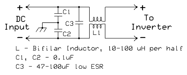
Noise filter on the DC input.  It looks suspiciously like the filter on the AC output - because it's the same type, although the current-carrying capacity of L1 is much higher and the values of the capacitors are orders of magnitude larger.
Click on the image for a larger version.

Filtering the DC input:

While I would presume that most of the noise would be emitted via the AC output port, filtering the DC port must be considered as well.  With the inverter's rating being 150 watts, the maximum current on the AC output would be around 1.25 amps and rather light-gauge wire could be used in the inductors - but because this same power level represents 12.5 amps at 12 volts (likely more if the battery voltage is on the low side) the filtering inductance must be made using much larger wire.

Rummaging around in my box of toroids, I found a ferrite device that was about 1" (2.54cm) in outside diameter and wound as many turns of 14 AWG flexible wire onto it as would fit (about 6 bifilar turns) and measured it to have about 30 uH of inductance per winding.  This may not seem like much, but at 1 MHz, this represents about 180 ohms of reactance.   

In referring to Figure 5, above, you'll notice that it is pretty much identical to that of the output filter - except that there is only one section of filtering.  The capacitor values are different, too:  C1 and C2 are 0.1uF units that shunt residual RF getting through L1 to ground (the case) while C3 is a low-ESR electrolytic connected across the DC leads to help force any residual AC noise on the DC lead to common-mode.  Compared to the 180 ohms of reactance of the DC bifilar choke (at 1 MHz) a good-quality, monolithic ceramic capacitor like the 0.1uF units are likely to have well under an ohm of impedance and very little of the RF hash will remain after they do their job to bypass it to the chassis ground.

Figure 6:
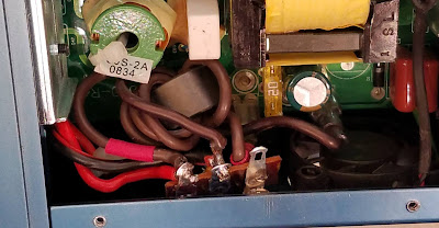
The DC input filter.  The capacitors (not visible) are mounted
to the bottom side of the terminal strip, which serves as the
RF "grounding" point to the case.  L1 is just visible.
Click on the image for a larger version.

Because of the limited amount of room, only one inductor was used - although it would likely be possible to have crammed another in the limited space should the above filter have proved to be inadequate (it wasn't).

As can be seen in Figure 6, a small terminal strip is visible and to it is mounted C1-C3 (not visible as they are obscured by the strip itself).  The mounting point for this strip is the ground lug near the DC input cable and the center lug is the common point for C1 and C2.

An important point to mention is the fact that this inverter - like many - have their DC and AC lines isolated from the case - and that's also important here:  Because the DC has no connection to the inverter's metal case, ALL of the DC current passes through L1 of Figure 5 - but with both halves carrying the same current, the core is not magnetized:  Magnetizing the core would likely cause it to saturate and the result would be its effective inductance plummeting - possibly reducing its efficacy as an RF filter.  It is for this reason that a bifilar choke was used on the DC input as well.

As with the AC output, the "inverter" side of L1 of Figure 5 also lacks a common-mode capacitor, but this is well represented on the input of the inverter itself with its own, built-in capacitor.

Figure 7:
The final arrangement of the added filtering components.  Liberal use of RTV (silicone adhesive) was used to stabilize the components as it works well, and can be removed should repairs/modifications be required.  On the left, a generous blob of RTV has been used to keep the terminal strip's lugs at the DC input from touching the inverter's bottom cover.
Click on the image for a larger version.

Additional comments:

Figure 7 shows the final arrangement of the added components.  In the upper-left corner can be seen the components of the DC input filter with come clear RTV (silicone adhesive) added to the top of the terminal strip to insulate it and keep any metal parts of it from touching the bottom cover when it was reinstalled.

On the right side is the AC output filter and on the foreground can be seen L2, now with the "hot" terminals covered by heat-shrink tubing.  This choke was first attached "temporarily" to the inverter's end plate using instant (cyanoacrylate) glue - and then several large blobs of RTV were later added to permanently hold it in place.  Just above it can be seen the orange wires that connect L2 to L1 and these components were also stabilized with rather large blobs of RTV to keep them from "flapping in the breeze".  It's worth noticing that the original ferrite cylinder is still on the AC output connection (on the black and white wires) where it connects to L4 - mainly because there was still room for it, and its efficacy, such as it is, is likely only enhanced by the addition of the new filtering components. 

Did it work?

You might ask the question:  Did this filtering work?

The answer is yes.  Placing a portable shortwave radio next to either the DC or AC power leads from the inverter, one can't detect that it is running at all.  If the radio is placed right atop the inverter, some hash can be detected, but this is likely from direct radiation of magnetic fields from the inductors/transformers within, but detectable amounts do not appear to be emanating from DC and AC wires themselves - and that's the important part as they would otherwise be acting as antennas.

Perhaps the most important part of this modification is the fact that any bypass capacitors are placed on the "quiet" (not the inverter) side of the filtering inductances and that these bypass capacitors are connected, with short leads, to a large, common-point ground - namely the case of the inverter.  If any of the "ground" leads had been more than an inch or two long, it's likely that the impedance of it would have reduced the efficacy of the filtering - but the case, being a solid chunk of extruded aluminum, forms a nice, low-impedance tie point - effectively a single-point ground, preventing an RF current differential between the DC input and AC output leads.

* * * 

Follow-up:

I've used this (modified) inverter several times, running strings of LED lights to illuminate the area around the camp site - often within a few feet (a meter or so) of the HF antenna and there was NO noise audible whatsoever from the inverter in the form of birdies from switching harmonics.

What was slightly audible was "space modulation" caused by the diode action of the LEDs themselves at the 60/120Hz AC frequency causing a small amount of amplitude modulation on received signals.  Interestingly, there was no audible noise generated by the LEDs themselves across the HF spectrum.

* * *

Links to other articles about power supply noise reduction found at ka7oei.blogspot.com:


This page stolen from ka7oei.blogspot.com

[End]


Tuesday, September 28, 2021

Pink bits of rubber causing a blinking light... (Problems with Jeep Rubicon sway bar disconnect mechanism)

 A bit more than a week ago I volunteered for an aid station along the route of the Wasatch 100 mile endurance run - which, as the name implies, is a 100 mile race, starting and ending some distance apart in Northern Utah.  This year, I was asked to be near-ish the start of the race, about 20.9 miles (30.4 km) from the start at a location in the mountains, above the Salt Lake Valley - a place that required the use of a high-clearance and somewhat rugged vehicle - such as my 2017 Jeep Rubicon.

Figure 1:
The blinking "Sway Bar" light - not something that you
want to see when you have shifted out of four-wheel drive!
Click on the image for a larger version.

Loaded with several hundred pounds of "stuff" I went up there, bouncing over the rough roads and despite enduring several bouts of rain, hail, lightning and thunder, managed to do what needed to be done in support of the race and runners and headed down.

Because of the rather rough road, I decided to push the button marked "Sway Bar" that disconnects the front left and right front tires from each other, allowing more independent vertical travel of each wheel, making the ride smoother and somewhat improving handing over the rougher parts.  Everything went fine until - on the return trip, near the bottom of the unimproved portion of the mountain road, I pushed the button again and...  the light kept blinking, on for a second and off for a second - and a couple minutes later, it started blinking twice as fast, letting me know that it wasn't "happy".

"What's the problem with that?"

Pretty much all modern road vehicles have a sway bar - or something analogous to it - that couple the vertical travel of the wheels on the same axle together to reduce body roll, which improves handling as one makes a turn - particularly around corners.  At low speeds, such roll isn't too consequential, but at high speeds excess roll can result in... well... "problems" - which is why I was a bit apprehensive as I re-entered the city streets.

Knowing that this type of vehicle is known for "issues" with the sway bar disconnect, I did the normal things:  Pushed the button on and off while rocking the vehicle back and forth (while parked, of course!), stopped and restarted the engine - and even pulled the fuse for the sway bar and put it back in - all things suggested online, but nothing seemed to work.

Stopping at a parking lot and crawling under the front of the vehicle while someone else rocked it back and forth did verify one thing:  Despite the indicator on the dashboard telling me that the sway bar wasn't fully engaged, I could see that it was, in fact, locked together as it should be as evidenced by the fact that the two halves of the bar seemed to move together with the vehicle's motion - so at least I wasn't going to have to drive gingerly back on the freeway.

Fixing the problem:

Figure 2:
Sway bar and disconnect mechanism, removed from the
vehicle with the lead screw/motor in the upper-right.
Click on the image for a larger version.
As mentioned before, this is a common problem with this type of vehicle and online, you will find lots of stories and suggestions as to what might be done.  Quite a few people just ignore it, others have it fixed under warranty - but those that have vehicles out of warranty seem to mostly retrofit it with a manual disconnect, if they care about the sway bar at all.

The reasons for the issue seem to be various:  Being an electromechanical part that is outside the vehicle, it's subject to the harsh environment of the road.  Particularly in the case of some die-hard Jeepers (of which I'm not particularly, although I've made very good use of its rough and off-road capabilities) reports online indicate that it is particularly prone to degradation/contamination if one frequently fords rivers and spends lots of time in the mud:  Moisture and dirt can ingress the mechanism and cause all sorts of things to go wrong.

Fortunately, one can also find online a few web pages and videos about this mechanism, so it wasn't with too much trepidation that, a week after the event - when I was going to change the oil, filters and rotate the tires anyway - I put the front of the vehicle on jack stands and removed the sway bar assembly entirely.  This task wasn't too hard, as it consisted of:

  • Remove the air dam.  My vehicle had easily removable plastic pins that partially popped apart with the persuasion of two screwdrivers - and there are only eight of these pins.
  • Disconnect the wire.  There's a catch that when pressed, allows a latch to swing over the connector, at which point one can rock it loose:  I disconnected the wire loom from the bracket on the sway bar disconnect body and draped it over the steering bar.
  • Disconnect the sway bar at each of the wheels.  This was easy - just a bolt on either side.
  • Undo the two clamps that hold the sway bar to the frame.  No problem here - just two bolts on each side.
  • Maneuver the sway bar assembly out from under the vehicle.  The entire sway bar assembly weighs probably about 45 pounds (22kg) so it's somewhat awkward, but it isn't too bad to handle.

Figure 3:
Inside the portion where the lead screw motor
goes:  Very clean - no contamination!
Click on the image for a larger version.
Before you get to this point I'd recommend that anyone doing this take a few pictures of the unit and also watch one or two YouTube videos as you'll want to be sure where everything goes, and under which bolt the small bracket that holds the wiring harness goes.

With the sway bar removed from the vehicle, I first  removed the end with the motor and connector and was pleased to find that it was perfectly clean - no sign at all of moisture or dirt. Next, I removed the other half of the housing, containing the gears and found that this, too, was free of obvious signs of moisture or dirt:  The only thing that I noticed at first was that the original, yellow grease was black in the immediate vicinity of the gears and the outside ring - but this was likely to due to the very slight wear of the metal pieces themselves.

The way that this mechanism works is that the motor drives a spring-loaded lead screw, pushing an "outside" gear (e.g. one with teeth on the inside) by way of a fork, away from two identical gears on the ends each of the sway bar shafts which decouples them - and when this happens, they can move separately from each other.  The use of a strong spring prevents stalling of the motor, but it requires that there be a bit of vehicle motion to allow the outside gear, under compression of the spring, to slip off to decouple the two shafts as they try to move relative to each other.

Figure 4:
The fork with the outside gear-cam thingie.  To disengage
the sway bar, the outer gear is pushed out further than
shown, disconnecting it from the end of the sway bar
seen in the picture above and allowing the two halves of
the rod to move independently.
Click on the image for a larger version.
When one "reconnects" the sway bar for normal driving, the motor retracts the lead screw and another (weaker) spring pushes the fork that causes tension on the outside gear so that it will move back, covering both of the gears on the ends of the  sway bar.  Again, some vehicle movement - particularly rocking of the vehicle - is required to allow the two gears to align so that the outer gear can slip over the splines and lock them into place.

In order to detect when the sway bar shafts are coupled properly, there's a rod that touches the fork that moves the outer gear and this goes to a switch to detect the position of the fork - and in this way, it can determine if the sway bar is coupled or uncoupled.  With everything disassembled, I plugged the motor unit back in and pushed the sway bar button and the lead screw dutifully moved back and forth - and pushing on the bar used to sense the position of the fork seemed to satisfy the computer and when pushed in, it happily showed that the sway bar was properly engaged.


What was wrong?

I was fortunate in that there seemed to be nothing obviously wrong mechanically or electrically (e.g. no corrosion or dirt) - so why was I having problems?

I manually moved the fork back and forth, noticing that it seemed to "stick" occasionally.  Removing the fork and moving just the outer gear by itself, I could feel this sticking, indicating that it wasn't the fork that was hanging up.  Using a magnifier, I looked at the teeth of the gears and noticed some small blobs in the grease - but poking them with a small screwdriver caused them to yield.

Figure 5:
Embedded in the grease are blobs of pink rubber
from the seal, seen in the background.
Click on the image for a larger version.

Digging a few of these out, I rubbed them with a paper towel and discovered that they were of the same pink rubber that comprised the seals:  Apparently, when the unit was manufactured, either the seal was pushed in too far, or there was a bit of extra "flash" on the molded portion of the seals - and as things moved back and forth, quite a few of these small pieces of rubber were liberated, finding their way into the works, jamming the mechanism.

Using tweezers, paper towels, small screwdrivers and cotton swabs, I carefully cleaned all of the gears (the two sets on the sway bar ends and the "outside" ring gear) of the rubber.  A bit of inspection seemed to indicate that wherever these rubber bits had been coming from had already worn away and more were not likely to follow any time soon.

Figure 6:
More pink blobs - this time on the gear on the other sway bar.
Hopefully whatever "flash" from the seal had produced them
has since worn down and no more will be produced!
Click on the image for a larger version.

Putting an appropriate of synthetic grease to replace that removed, I reassembled the unit and put it back on the car, pushed the button.  Upon reassembly, I applied a light layer of grease on all of the moving surfaces involved with the shifting fork - some of which may have been sparsely lubricated upon installation.  I also put a few drops of light, synthetic (PTFE) oil on the leadscrew and the shaft that operated the sensing switch as both seemed to be totally devoid of any lubrication.

Although there was no sign of corrosion, I applied an appropriate amount of silicone dielectric grease to the electrical connector and its seal - just to be safe.

Did it work?

With the engine off, but in "4-Low", I could hear the lead screw motor move back and forth, and upon rocking the car gently I could hear the fork snap back and forth as it sought its proper position.  Meanwhile, on the dashboard, the "Sway Bar" light properly indicated the state of the mechanism:  Problem solved!

All of this took about two hours to complete, but now that I know my way around it, I could probably do it in about half the time.

Random comments:

I'd never really tried it before, but I was unsure if the motor would operate if the engine was not running:  It does - pressing the "Sway Bar" button alternately winds the lead screw in and out - but it's not really obvious as to its position if the cam doesn't lock into place and the light turns on solid or goes out.  Of course, this thing doesn't operate unless one has shifted to four wheel drive, low range.

June 2023 update:

I have had - and continue to have - NO problems at all with the sway bar mechanism.  When I push the button to disconnect or - in particular, reconnect - it does so immediately - something that did not always happen prior to my working on it.

This page stolen from ka7oei.blogspot.com.

[End]

Wednesday, June 30, 2021

A "portable", high power, high-sensitivity remote repeater covering deep river gorges in Utah

From the late 1950s until about 2012 there was a (mostly) annual event held in southeastern Utah that was unique to the local geography:  The Friendship Cruise.

The origins are approximately thus:  In the late 1950s, an airboat owner - probably from the town of Green River, Utah - decided to go down the Green River, through the confluence of the Green and Colorado rivers, and back up to the town of Moab.  Somehow, that ballooned into a flotilla in later years - with as many as 700 boats - in the 60s and 70s.  By the mid 90s, interest in this unique event seemed to have waned and by about 2012, it finally petered out.

Communications is important:

Figure 1:
A high-Q 80 meter magnetic loop
on one of the rescue boats
Click on the image for a larger version
From the beginning it was realized that there was a need for the boats and support crews to be able to communicate with each other - but the initial attempts using CB and/or public safety VHF radios were unsuccessful, reaching only a few miles up and down the river - not too surprising considering that most of the course runs through winding, deep (1200 foot deep, 365 meter) gorges.  In later years, cell phones - and even satellite phones - were tried, but due to the remoteness and narrowness of the gorges (and limited view of the sky) they were of extremely limited use.

At some point, probably in the mid 1960s, amateur radio operators got involved, successfully closing the communications link using the 80 meter amateur band.  This tactic worked owing to the nature of 80 meters:  During the daytime, coverage is via skywave over a radius of about 200 miles (300km) and this high angle of radiation allowed coverage into and out of the deep canyons.  Furthermore, the same antennas that were small enough to be usable on boats, vehicles and temporary stations on this band were well-suited for radiation of RF energy at these steep angles.

For (literally!) decades, this system worked well, providing coverage not only anywhere on the river, but also to the nearby population centers (e.g. Salt Lake City) where other amateur radio operators could monitor and relay traffic as necessary and summon assistance via land line (telephone) if needed.  Because the boats were typically on the river only during the day, this seemed to be a good fit for the extant propagation.

While it worked well, it was subject to the vagaries of solar activity:  An unfortunately-timed solar flare would wipe out communications for hours at a time, and powering and installing a 100 watt class HF transceiver and antenna was rather awkward.  Occasionally, there was need to communicate after dark, and this was made difficult by the fact that 80 meters will go "long" after sunset - often requiring stations much farther away (e.g. in California or Nebraska) to relay to stations just a few 10s of miles away on the river!  Finally, it was a bit fatiguing to the radio and boat operators to have to listen to HF static all day long!

Enter VHF communications:

Figure 2:
General coverage map of the course
showing coverage of various sites.
Click on the image for a larger version
While VHF communications had been tried early on - and had been available in the intervening years - the biggest problem was that these signals could not make their way along the river for more than a few miles between twists and bends in the deep river gorges.  While useful for short-range communications, it simply wasn't suitable for direct boat-to-boat communications along the vast majority of the river's course.

By the time that the 1990s had come along, there was renewed interest in seeing if we could make use of VHF, on the boats, on the river.  The twist was that instead of direct communications between boats, we would try to relay signals from far above, on the plateaus farther away, and a few experiments were tried.  It 1996, I was on a boat on the river and took notes on what sites covered and where, trying nearby mountaintop repeaters and temporary stations set up at places near-ish the river courses themselves - the resulting map being presented in Figure 2.

Using the color-coded legend across the top and the markings on the map itself, one can see what sites covered where.  Included in this was the coverage from the 147.14 repeater near-ish Green River, Utah, the 146.76 repeater near Moab, and several other temporary sites atop the plateaus surrounding the river.  As can be seen, coverage was spotty and inconsistent over much of the route - with the exception of a site referred to as "Canyonlands Overlook" (abbreviated "Cyn Ovlk") which commanded a good view of the Colorado River side of the river course.  Clearly missing was reasonable coverage in the depths of the gorges along the lower parts of the Green River side - which started, more or less, where the coverage of the "Spring Canyon" (abbreviated "Spring Cyn") stopped.

Figure 3:
The two TacTecs used for 2 meter reception,
the voting controller (blue box) and the FT-470 used
as the UHF link radio.
Click on the image for a larger version.
As it happened, there were amateur radio operators camping at a site called Panorama Point when I was on the lower Green River and because we were using the Utah ARES simplex frequency, they just happened to hear the simplex activity on the river.  At that moment, I happened to be in areas that were not well-covered by any of the other sites and while their signals weren't extremely strong, it made me wonder what could be accomplished should I wield both gain antennas on the receiver and high power and gain antennas on the transmitter of a 2 meter repeater.

The birth of a repeater:

During the next year I put together a system that I'd hoped would make the most of the situation.  Because of the remoteness of the site, accessible via a high-clearance Jeep road - and that we had to bring everything to live for a few days, it had to be relatively lightweight and compact - and I also wanted to avoid the use of any duplexers (large cavity filters) that would add bulk and - more importantly - losses to the system.  Taking advantage of a weekend to visit Panorama Point the next spring we determined that we could split the transmit and receive portions by about 0.56 miles (0.9km) apart, placing the receive antennas behind some local geographical features and using local topography to improve isolation.  The back-of-the-envelope calculations indicated that this amount of separation - and the rejection off the backs and sides of the beam antennas - would likely be sufficient to keep the receiver out of the transmitter.  The receive site - surrounded by three sides by vertical cliffs - also provided a commanding view of the terrain as can be seen in Figure 5, below.

Figure 4:
GaAsFET preamplifier mounted right at the
receive antenna to minimize losses.
Click on the image for a larger version.

In addition to site separation and gain antennas, I decided to go overboard, adding mast-mounted GaAsFET preamplifiers, right at each antenna (Figure 4) and implementing a voting receiver scheme - something made much easier with the acquisition of two, identical RCA TacTec "high band" VHF transceivers.  These receivers were modified - clipping the power lead to the transmitter and adding a 3.5mm stereo plug to each radio to bring out both discriminator audio and the detector voltage from the squelch circuit.

A relatively simple PIC-based repeater controller was constructed, using a simple comparator to determine which receiver had the "best" signal, based on the detector voltage from the squelch circuit, and also using another set of comparators and onboard potentiometers to set the COS (squelch) setting for the receivers.  As it turned out, the front-panel squelch control adjusted the gain in front of the squelch detectors in the radios themselves, allowing each receiver to be "calibrated" from that control, allowing easy fine-tuning in the field.

To link the receiver site to the transmitter site, a single UHF channel was used and I modified my old Yaesu FT-470 handie-talkie to this task.  The mysterious rubber plug on the side of this radio was replaced with a 3.5mm jack, providing a direct connection to the modulation line of the UHF VCO while using the top panel 2.5mm external microphone jack for transmitter keying.  As it turns out, not only did this transmitter provide linking to the nearby transmitter site, but its UHF beam was pointed across the way, to another 2 meter repeater at Canyonland's Overlook that provided coverage on the Colorado River - providing what amounted to a linked repeater system.  A later addition was a CdS photocell on a grommet and a piece of "Velcro" strap allowed the detection receiver activity by "looking" at the front-panel LED to prevent the link transmitter from "doubling" (transmitting at the same time) and clobbering an ongoing transmission from the other repeater site.

Figure 5:
The remote RX site, surrounded on
3 sides by sheer cliffs.  The mast
has two 2 meter and one UHF link
beam antenna.  The solar panels are
just visible along the far right edge.
Click on the image for a larger version.
One of my goals was to minimally process the audio, causing as little "coloration" as possible to maintain quality, and to this end I took the receivers' discriminator audio from the voter and put it directly into the modulator of the UHF link radio, completely avoiding the need for de-emphasis and pre-emphasis.  This worked pretty well - but I noticed during the first year that it was used that when weak signals were present on the input, the noise and hiss from weak signals would sometimes cause "squelch clamping" on the receivers being used by us and others owing to the fact that such noise was being passed along the link without alteration:  For the next year I added a 3.5 kHz low-pass filter in the transmit audio line to remedy this.

The receive site itself was solar-powered, using lead-acid batteries to provide the energy when insufficient sun was available (e.g. heavy clouds, night).  In later years, the PIC controller was modified to not only read the battery voltage, but to regulate the solar panels' charging of the battery bank using a "bang-bang" type charger (See note 1) but also to report the battery voltage when it did its legal identification.  In this way, we could keep an "eye" on things without having to walk out to the receive site.

The two 2 meter and the 70cm link antennas were mounted on a single mast, the VHF antennas pointed in different directions to take advantage of the slight difference in physical location and in the hopes of providing diversity for  the weak signals from the depth of the canyons - which were all reflections and refractions.  As it turns out, despite the close proximity of the antennas, this worked quite well:  At the site, one could monitor the speakers on the receivers and watch the voting controller's LED and see and hear that this simple, compact arrangement was, in fact, very effective in reducing the number of weak-signal drop-outs caused by the myriad multipath.

In testing on the work bench, the measured 12dB SINAD sensitivity of each of the receivers (plus GaAsFET preamps) was on the order of 0.09 microvolts - far and away better than a typical receiver.  Later, I did the math (and wrote about it - see the link at the bottom of this article) and determined that it was likely that the absolute sensitivity of this receiver was limited by the thermal noise of the Earth itself and that it could not, in fact, be made any more sensitive.  This notion would appear to be borne out by a careful listening to the repeater in the presence of weak signals:  Very weak signals - near the receive system's noise floor - sounded quite different than what one might hear on a typical FM receive system near it's noise floor.  Instead of a "popcorn" type noise, signals seemed to gradually disappear into an aural cloud of steam.

The transmitter site:

Figure 6:
The transmit site.  The tall (30 foot) mast and 2 meter transmit
antenna is visible in the background with the UHF link
antenna and the VHF "backup" TX antenna in the foreground.
Click on the image for a larger version.

With so much effort having gone into maximizing receiver performance I decided to do the same on the transmit site in the years that this system was used.  For the first year, the transmitter was modest:  A Kenwood TM-733, on low power, driving a 50 watt RF amplifier into a vertical on a short mast.

The next year I decided to erect a taller mast and place atop it a 5 element beam, pointed in the general direction of "up river".  To boost my RF output power, I scavenged a pair of 110 watt RF amplifiers from some ancient Motorola Mocom 70 mobile radios (with some DC fans for cooling) and used two Wilkinson Power divider - one to split the input power and another to combine the outputs of the amplifier, yielding a bit over 200 watts of RF and about 1500 watts of ERP (Effective Radiated Power) - all without causing any measurable desensitization of the receiver system.  After a few days, one of these amplifiers failed, but the remaining 110 watt amplifier, now operating without the output combiner, happily chugged along.

The next year I acquired a 300 watt Vocomm amplifier and was able to use it for the remainder of the times that the Friendship Cruise was held.  Requiring 50 watts of drive, I still had to use the 50 watt amplifier, driven by 5 watts from the TM-733 to attain the full RF output.  When keyed down, the entire transmitter system drew about 60 amps at 12 volts from the battery bank, requiring frequent topping-off by a generator and DC power supply that were brought along. (See note 2)

With that much transmit power, the antenna was held aloft by a 30 foot (9 meter) mast to keep it away from people - and to help clear the local terrain and its effects.  As can be seen in Figure 6, there was a second mast with the UHF link antenna and a "back-up" 2 meter antenna.  When we arrived at the site, the first order of business was usually to set up the receive site, but once back at camp, we used a radio in cross-band mode and the two antennas on this short mast to get it on the air, providing "reasonable" transmit coverage.  Because of the effort required to set up the tall mast, battery bank and power amplifier, we often waited until the next morning to complete the setup, bringing our radiated transmit power up to its full glory!

"Listening" on the link frequency, this transmitter not only relayed my own, nearby receive site, but also the "other" repeater at Canyonland's Overlook. 

How well did it work?

The Panorama Point repeater itself worked better than we could have hoped:  It was "reachable" nearly everywhere on either the Green or Colorado River - although some sections of the upper Green and Colorado had somewhat weaker signals, requiring a good antenna and 50 watt radio - comparable to a typical car mobile installation - for reliable coverage.  Unexpectedly, it also provided coverage into the town of Moab, as far north as Price, Utah and even down near Hite, Utah - both well outside its expected coverage range and well outside the expected pattern of the beam antennas.

I'm confident that if I'd simply plopped down a "store bought" repeater with a single antenna and cavities, its performance - particularly on receive - would have been very much inferior as the signals from the depths of the gorges on the upper Green River were very weak and "multipathy". (See note 3)

With about 2.5kW of ERP one would expect that this repeater would have been an "alligator" (all mouth, no ears) but this was not the case:  When users were operating from the more extreme fringe areas - as in a deep river gorge, using a 50 watt mobile radio - the transmitter and receiver seemed to be more or less evenly matched, and despite running this much power, we did not experience any detectable "desense" where the strong transmit signal would overload the receiver.  At least part of this was attributed to the receivers themselves:  The RCA TacTec receivers used only modest amounts of RF gain in their front ends and a passive diode-ring mixer.  I have little doubt that if we had used more "modern" receivers we would have experienced overloading and would have had to place notch cavities, tuned for the transmit frequency, between the GaAsFET preamps and the receivers.

As a system, the Panorama Point and Canyonlands Overlook repeaters completely replaced the need for HF gear on the boats in the last decade or so that the Friendship Cruise was held, providing nearly seamless coverage from start to finish.

 * * *

Note 1:   A "bang-bang" solar regulator simply connects the solar panels directly to the battery when the voltage is too low - say, 13.2 volts - and disconnects them again when it rises above about 13.7 volts.  The PIC software implemented a timer so that after a disconnect from the panel when the voltage was high, it would not reconnect for at least 30 seconds, preventing rapid cycling.  With an open-circuit voltage of around 15 volts for the panels used, this was a simple, safe and reasonably efficient approach that could simply not cause radio-frequency interference in the way many modern "MPPT" solar chargers (with their PWM switching) might.

Note 2:  In the later years, a pair of 40 amp switching power supplies were used at the transmitter site to charge the battery as quickly as possible.  Not unexpectedly, we could load the generator to only about 60% of its rated output, owing to the terrible power factor of these supplies caused by their simple capacitor inputs:  Power-factor corrected supplies were not cheap and readily available at that time.  Also in later years, a very low power (1 milliwatt) 2 meter transmitter was constructed, connected to the battery bank, that telemetered the battery voltage using MCW (Morse Code).  If the battery voltage got too low, this transmitter would activate a subaudible tone and a receiver that had been parked on this frequency, configured to detect that tone, would remain silent unless/until the voltage dropped below the threshold, alerting us to the need to start the generator.

Note 3:  "Multipath" is when a signal - likely due to obstructions - finds more than one way to the other end of the communications path via reflection and refraction - a condition that is the rule rather than the exception when trying to get signals in/out of the deep gorges along these rivers.  While these multiple signals can reinforce each other, they are equally likely to cancel each other out.  By having multiple receivers and antennas - even two antennas very close to each other - the probability is significantly higher that at least one of the receiver/antenna combinations will be able to hear such a signal.  Because of the nature of FM signals, one can generally infer its quality by analyzing the amount of noise on it:  By comparing the amount of noise on the same signal, from two different receiver/antenna combinations - and always selected the "better" signal - the probability is increased that the received transmission will suffer less degradation.

* * *

Additional (related) articles:

This page stolen from ka7oei.blogspot.com

[End]